manuals.online logo
Brands
  1. Home
  2. •
  3. Brands
  4. •
  5. Makita
  6. •
  7. Impact Driver
  8. •
  9. Makita BTW201 Manual

Makita BTW201 Manual

Models No.
Description
NEW TOOL
TECHNICAL INFORMATION
CONCEPTION AND MAIN APPLICATIONS
Specification
Standard equipment
Optional accessories
< Note > The standard equipment for the tool shown may differ from country to country.
P 1 / 9
Dimensions : mm ( " )
Width ( W )
Height ( H )
Length ( L )
86 (3-3/8)
277 (10-7/8)
226 (8-7/8)
H
L
W
BTW201
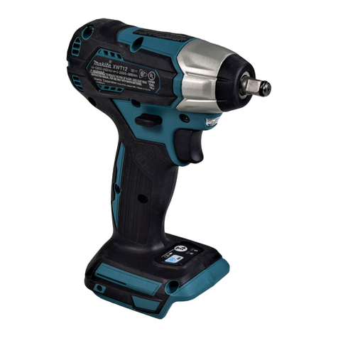
24V Cordless Impact Wrench
The variations of this model are as listed below.
Model No. Battery Q'ty Type of cell Charger
BTW201SH B2417 (1.7Ah) 1pc. Ni-MH DC24SA
BTW201SF B2430 (3.0Ah) 1pc. Ni-MH DC24SA
No load speed : (min -1= rpm)
Blows per min : (min -1= bpm).
Drive shank : mm=( " )
Max. fastening torque
BPM. pre-selection system
Reverse switch
Capacity Standard bolt
High tensile bolt
200 Nm
(2,040 kgf.cm, 1,770 in.lbs)
0 - 2,000
0 - 3,000
Square 12.7 (1/2)
M10 - M12 (3/8 - 1/2)
M10 - M16 (3/8 - 5/8)
Net weight including battery B2417 2.9Kg (6.3 lbs)
Yes
Yes
Battery
Voltage ( V )
Capacity (Ah)
Type of cell Ni-MH
3.0
24
* Socket 19-52 ....................... 1 pc.
* Pin 4 ........................ 1 pc.
* O ring 24 ........................ 1 pc. ( Except North American market)
* Various Sockets
* Battery B2417 / 1.7 Ah
* Battery B2430 / 3.0 Ah
* Charger DC24SA
* ADP01 Interchangeable adapter
* ADP02 Refreshing adapter
Model BTW201 can compete with the existing 360W class
AC tool, Mod.6904VH in max. fastening torque.
And its BPM. Pre-selection System prevents the over-tightening.
Features and benefits P 2 / 9
BPM. pre-selection system
The machine stops automatically, when the equipped
bpm. sensor perceives the pre-select bpm.
And the over tightening can be avoided with
BPM. pre-selection system.
Consequently, Mod.BTW201 is suitable for fastening work
in the section where the fastening torque is directed in advance.
Bottom view of grip end
(View from terminal side)
226mm
Compact overall length : only 226 mm 200 N.m is the most strongest
fastening torque among
cordless machines, and
same as Mod.6904VH, 360 W AC tool.
Newly developed 24V Ni-MH batteries
(B2417 / 1.7 Ah and B2430 / 3.0 Ah) can
be used for Mod.BTW201.
Long life DC motor with
externally accessible brushes
Aluminum hammer case
with rubber cover
Palm fitly soft grip with ergonomically
shape for comfortable gripping
12.7mm (1/2") square drive
Push button for reversing
Variable speed control switch
0
1
2
3
4
5
6
7
8
9
A
B
C
D
E
F
0
1
2
3
4
5
6
7
8
9
How to pre-select BPM.
0
1
2
3
4
5
6
7
8
9
A
B
C
D
E
F
0
1
2
3
4
5
6
7
8
9
BPM. pre-select dial
The first digit
The second digit
(The alphabet means
working mode for
special employment.)
BPM. pre-select dial is located in the grip end
as illustrated above,
and it can be found easily, when the battery
is taken off.
BPM. can be set by turning the dial
with flat head screwdriver so that the dial's arrow
align with the numbers or alphabet indicated on the
machine's body.
The figures mean as illustrated in Fig.A - Fig.C.
See next page.
Features and benefits P 3 / 9
If you want 196 bpm., align the pre-setting dial of the second
digit with 9 and the same of the first digit with 8 as illustrated
in Fig.A. Namely, 98 x 2 = 196 bpm.
0
1
2
3
4
5
6
7
8
9
A
B
C
D
E
F
0
1
2
3
4
5
6
7
8
9
The second digit The first digit
If you want more than 200 BPM., align the both
pre-setting dials with 9 as illustrated in Fig. C.
In this case, Mod.BTW201 is used as an normal
cordless impact driver with 0 - 3,000 bpm.
0
1
2
3
4
5
6
7
8
9
A
B
C
D
E
F
0
1
2
3
4
5
6
7
8
9
The second digit The first digit
If you want 104 bpm., align the pre-setting dial
of the second digit with 5 and the same of
the first digit with 2 as illustrated
in Fig.B. Namely, 52 x 2 = 104 bpm.
0
1
2
3
4
5
6
7
8
9
A
B
C
D
E
F
0
1
2
3
4
5
6
7
8
9
The second digit The first digit
Fig.A
Fig.C
Fig.B
Indications and functions
0 - 9 1 - 8
0
1
2
3
4
5
6
7
8
9
A
B
C
D
E
F
0
1
2
3
4
5
6
7
8
9
99
0
1
2
3
4
5
6
7
8
9
A
B
C
D
E
F
0
1
2
3
4
5
6
7
8
9
00
0
1
2
3
4
5
6
7
8
9
A
B
C
D
E
F
0
1
2
3
4
5
6
7
8
9
Dial pre-selection Clockwise rotation Anti-clockwise rotation Purpose
The machine stops automatically,
when its sensor perceives the
pre-selected bpm which is
equivalent to double of the figures
selected with dial.
The machine starts or stops with
operation of the trigger switch.
The machine starts or stops with
operation of the trigger switch.
Mode of reverse switch
The fastening work
of bolts for which
the bpm. control is
required.
The fastening work
of bolts for which
more than 200 bpm.
is required, or
bpm. control is not
required.
The machine does not start
in spite of operation of switch
trigger.
The machine starts or stops with
operation of the trigger switch.
Fastening of bolts
The second
digit
The first
digit
The second
digit
The first
digit
The second
digit
The first
digit
Features and benefits P 4 / 9
Indications and functions
0
1
2
3
4
5
6
7
8
9
A
B
C
D
E
F
0
1
2
3
4
5
6
7
8
9
A0 - 9
BSelect any of
0 - 9
Select any of
0 - 9
0
1
2
3
4
5
6
7
8
9
A
B
C
D
E
F
0
1
2
3
4
5
6
7
8
9
C
0
1
2
3
4
5
6
7
8
9
A
B
C
D
E
F
0
1
2
3
4
5
6
7
8
9
Special purpose
Dial pre-selection Clockwise rotation Anti-clockwise rotation
Mode of reverse switch
If the dial of second digit is set on "A", the machine does not
start in spite of pulling trigger switch, or setting the dial of
first digit on any numbers.
Purpose
The machine stops after the
sensor perceives the first blow,
depending on the pre-selected
figures of the first digit.
For instance,
0 : Stop at one
1 : Stop 0.1 sec. later
2 : Stop 0.2 sec. later
9 : Stop 0.9 sec. later
The machine starts or stops
with operation of the trigger
switch.
Preliminary fastening
of bolts
The machine starts or stops
with operation of the trigger
switch.
Loosening of bolts
The machine stops after
stopping its blow, depending
on the pre-selected figures
of the first digit. For instance,
0 : Stop at one
1 : Stop 0.1 sec. later
2 : Stop 0.2 sec. later
9 : Stop 0.9 sec. later
The second
digit
The first
digit
The second
digit
The first
digit
The second
digit
The first
digit
0 - 9
0
1
2
3
4
5
6
7
8
9
A
B
C
D
E
F
0
1
2
3
4
5
6
7
8
9
D
E
0
1
2
3
4
5
6
7
8
9
A
B
C
D
E
F
0
1
2
3
4
5
6
7
8
9
Select any of
0 - 9
The second
digit
The first
digit
The second
digit
The first
digit
The machine does not start in
spite of pulling trigger switch,
but buzzers 0.2 sec. depending
on the pre-selected figure of
the first digit after pulling
trigger switch, . For instance,
0 : one time buzzer
1 : two times buzzer
2 : three times buzzer
9 : ten times buzzer
Checking the functions
mentioned below.
For instance
* BPM. pre-select dial
* Stop of motor
* Buzzer
F
0
1
2
3
4
5
6
7
8
9
A
B
C
D
E
F
0
1
2
3
4
5
6
7
8
9
Select 0 and 1
The second
digit
The first
digit
If the dial of second digit is set on "D", the machine does not
start in spite of pulling trigger switch, or setting the dial of
first digit on any numbers.
The machine starts, and stops
depending on the pre-selected
figure of the first digit after the
sensor perceives how many
times you have hit the housing,
For instance,
0 : stop with one time hitting
1 : stop with two times hitting
2 : stop with three times hitting
9 : stop with ten times hitting
If the dial of second digit is set on "F" and the same of the first
digit is set on zero or one, the following matters are informed.
0 : information of the version code of program
* Version code 2.1 : two long buzzers - long pause,
- one short buzzer
* Version code 3.2 : three long buzzers - long pause,
- two short buzzers
1 : information of the remaining voltage as follows.
* 23 V : two long buzzers - long pause - three short buzzers
* 20 V : two long buzzers
* 18 V : one long buzzer - long pause - eight short buzzers
* 9 V : nine short buzzers
Checking the version
code of program in the
controller
and
remaining voltage of
battery
Features and benefits P 5 / 9
The relation between bpm. and fastening torque
Fastening standard bolt Fastening high tensile bolt
0 0
20
40
60
80
100
100
25 50 75
150
120
140
N.m
(Kgf.cm) N.m (Kgf.cm)
(204) 20 (204)
(408)
40 (408)
(612)
60 (612)
(816)
80 (816)
(1,020)
100 (1,020)
(1,224)
120 (1,224)
(1,428)
140 (1,428)
160 (1,632)
180 (1,836)
200 (2,040)
220 (2,244)
240 (2,448)
260 (2,652)
(bpm.)
(Dial pre-
selection) 25 50 75 98 99 99 (Dial pre-
selection)
50
1 2 3 1 2 3 4 5 6
(Time: sec.) (Time: sec.)
Standard fastening
torque for M 16
Standard fastening
torque for M 12
Standard fastening
torque for M 10
M10 x 50
M12 x 50
M16 x 50
100 150 196 250 300 (bpm.)
50
Standard fastening
torque for M 12
Standard fastening
torque for M 10
M10 x 50
M12 x 50
Comparison of products
Model No. MAKITA
Specifications
Battery
High speed
Low speed
Voltage ( V )
Capacity (Ah)
Energy (Wh)
Max. fastening torque
No load speed
: (min -1= rpm) High
Low
Blows per min.
: (min -1= bpm)
High
Low
Electric brake
Overall length
Net weight including
battery B2417 / 1.3Ah :Kg
BTW201 BTW200
DC 24
1.7 / 3.0
40.8 / 72.0
DC 24
1.7 / 3.0
40.8 / 72.0
200
226
0 - 2,000 0 - 2,000
0 - 1,600
0 - 3,000
No
2.9
226
No
2.8
200
150
0 - 3,000
0 - 2,500
P 6 / 9
Repair
<1> Disassembling housing R and L
Take off bumper from housing with hand.
Dismount hammer case from housing by taking off
4 hex socket head bolts M5x35, and disassemble
housing R and L as illustrated in Fig. 1.
Hex socket
head bolts M5x35
Hammer case
Housing R
Housing L
Fig. 1
Bumper
<2> Apply 0.5g of MAKITA grease N No.2 on the
cylindric part of anvil, when inserting it into
hammer case.
Apply MAKITA grease N No.2
Anvil
Fig. 2
<3> Disassembling hammer section
(1) Grip the hammer section with large gear extractor No.1R045
as illustrated in Fig. 3.
Press spindle to hammer by turning the handle clock-wise
until it stops.
Fig. 3
1R165 Ring spring
setting tool B
Flat plate Turn the handle
clock-wise
Spindle
Hammer
Compression spring 14
No.1R045
Large gear extractor
Ball bearing 6002LLB
P 7 / 9
Repair
(2)Adjust the opening for steel ball inserting, to the cam groove top of spindle
as illustrated in Fig. 5.
Spindle
Cam groove top
of spindle
Opening for steel
ball inserting
Steel ball 5.6 x 2pcs.
Steel ball 4 x 25pcs.
Hammer
(3)Take off 2 pcs. of steel balls 5.6 with magnetic bar or tweezers from spindle.
(4)Loosen the handle of 1R045 turning it anti-clockwise
and remove hammer from spindle.
(5)When assembling, adjust the "opening for steel ball inserting", to the "cam groove top" of spindle
and insert steel ball 5.6 into hammer as illustrated in Fig. 5.
< Note > Set the hammer as per Fig.5A,
when removing it from spindle.
Otherwise steel balls 4
will fall off hammer.
Ball bearing
6002LLB
1R165 Ring spring
setting tool B
Fig. 5
Fig. 5A
(6) Apply MAKITA grease N No.2 in small volume to the position marked with black triangle mark.
See Fig. 6.
(1) Spindle
(3) Steel ball 5.6 x 2
(2) Steel ball 4 x 25pcs. Hammer
(4) Spur gear 24
Fig. 6
Bottom view of spindle
Apply MAKITA grease N No.2 in small volume
into the hole of spindle.
Repair P 8 / 9
< 4 > Removing ball bearing 6002LLB
This ball bearing can be removed
by pressing with arbor press.
Internal gear case
Round bar for arbor
Ball bearing 6002LLB
Fig. 7
< 5 > Fastening torque for tapping screws and bolts
The bolts and screws have to be fastened with the directed fastening torque as illustrated in Fig. 8.
And hammer case has to be fastened diagonally as illustrated in Fig. 9.
Tapping screw 4 x 18 : Approx. 1.27Nm - 1.76Nm
(10 Kgf.cm- 18 Kgf.cm)
Hex socket head bolt M5x 35 : Approx. 2.74Nm - 3.14Nm
(28 Kgf.cm - 32 Kgf.cm)
Hammer case
Fig. 8
Fig. 9
Circuit diagram
Wiring diagram
P 9 / 9
Terminal
M1
M2
Controller
Switch Motor
black
black
black
Orange
Orange
black
red
Brush holder lead wire
(Black)
Brush holder lead wire
(Red)
Terminal
M1
Do not slack the brush holder
lead wire (black )in this portion.
Fix lead wire (red and white)
with lead holder.
Do not pinch lead wire (black ) of
controller between switch holding rib
and switch. See the following illustration
in detail.
Controller
Do not pinch between these
switch holding ribs and switch.
Connecting brush holder lead wire (black) with switchConnecting brush holder lead wire (black) with switch
Take off the sheath so that
the size of wire portion is
approx. 7mm. And mount
connector to the wire portion.
Bent the lead wire, and
cover the connector and
lead wire with thermoplastic tube.
Connector Thermoplastic tube
Connect with switch.
Connecting brush holder lead wire (black) with switch
7mm
Lead wire pinched
with rib and switch

Other Makita Impact Driver manuals

Makita 6932FD User manual

Makita

Makita 6932FD User manual

Makita DTD152 User manual

Makita

Makita DTD152 User manual

Makita 6914D User manual

Makita

Makita 6914D User manual

Makita 6908D User manual

Makita

Makita 6908D User manual

Makita DTL060 User manual

Makita

Makita DTL060 User manual

Makita 6905B User manual

Makita

Makita 6905B User manual

Makita 6916D User manual

Makita

Makita 6916D User manual

Makita 6905B User manual

Makita

Makita 6905B User manual

Makita DTD157RAJ User manual

Makita

Makita DTD157RAJ User manual

Makita DTL060 User manual

Makita

Makita DTL060 User manual

Makita 6952 User manual

Makita

Makita 6952 User manual

Makita XT269M User manual

Makita

Makita XT269M User manual

Makita DTD171 User manual

Makita

Makita DTD171 User manual

Makita DTD154 User manual

Makita

Makita DTD154 User manual

Makita TD003GZ User manual

Makita

Makita TD003GZ User manual

Makita TW004GM201 User manual

Makita

Makita TW004GM201 User manual

Makita DTD137 User manual

Makita

Makita DTD137 User manual

Makita DTD129RTJ User manual

Makita

Makita DTD129RTJ User manual

Makita TD090D User manual

Makita

Makita TD090D User manual

Makita TW1000 Quick start guide

Makita

Makita TW1000 Quick start guide

Makita DTW1001 User manual

Makita

Makita DTW1001 User manual

Makita TD112D User manual

Makita

Makita TD112D User manual

Makita tw0200 User manual

Makita

Makita tw0200 User manual

Makita DTW300 User manual

Makita

Makita DTW300 User manual

Popular Impact Driver manuals by other brands

ACDelco ARI12105 Product information manual

ACDelco

ACDelco ARI12105 Product information manual

Narex EVP 13-2 R70 Original operating manual

Narex

Narex EVP 13-2 R70 Original operating manual

DeWalt DC830 instruction manual

DeWalt

DeWalt DC830 instruction manual

KRAFTWERK 3838 Operation manual

KRAFTWERK

KRAFTWERK 3838 Operation manual

Ryobi R18IDP Original instructions

Ryobi

Ryobi R18IDP Original instructions

Cornwell Tools CCT18IW operating instructions

Cornwell Tools

Cornwell Tools CCT18IW operating instructions

Craftsman 315.ID2025 Operator's manual

Craftsman

Craftsman 315.ID2025 Operator's manual

Sealey SA6004.V2 manual

Sealey

Sealey SA6004.V2 manual

Ingersoll-Rand 2135QXPA Product information

Ingersoll-Rand

Ingersoll-Rand 2135QXPA Product information

Milwaukee M18 FUEL 2757-20 Operator's manual

Milwaukee

Milwaukee M18 FUEL 2757-20 Operator's manual

Ferm Industrial CDM1142P Original instructions

Ferm Industrial

Ferm Industrial CDM1142P Original instructions

Dynabrade Autobrade Red manual

Dynabrade

Dynabrade Autobrade Red manual

Chicago Pneumatic CP724H series Operator's manual

Chicago Pneumatic

Chicago Pneumatic CP724H series Operator's manual

CLAS OP 1409 manual

CLAS

CLAS OP 1409 manual

Astro Pneumatic Tool 1833 manual

Astro Pneumatic Tool

Astro Pneumatic Tool 1833 manual

DeWalt DWMT70774 instruction manual

DeWalt

DeWalt DWMT70774 instruction manual

Milwaukee M18 FMTIW2P12 Original instructions

Milwaukee

Milwaukee M18 FMTIW2P12 Original instructions

Toku MI-17MG manual

Toku

Toku MI-17MG manual

manuals.online logo
manuals.online logoBrands
  • About & Mission
  • Contact us
  • Privacy Policy
  • Terms and Conditions

Copyright 2025 Manuals.Online. All Rights Reserved.