manuals.online logo
Brands
  1. Home
  2. •
  3. Brands
  4. •
  5. Makita
  6. •
  7. Power Screwdriver
  8. •
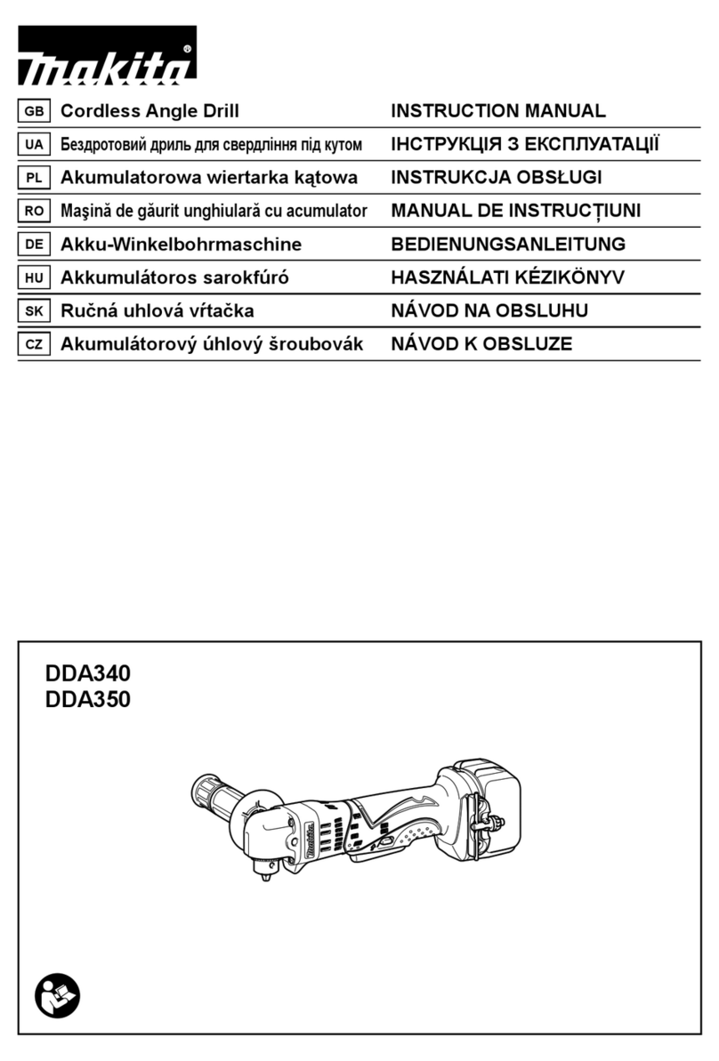
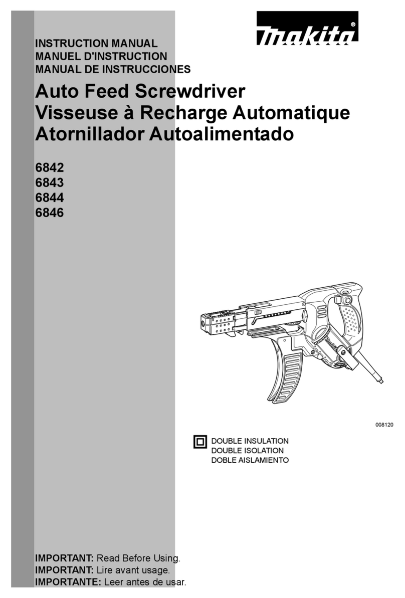
  9. Makita 6833 User manual

Makita 6833 User manual

Other manuals for 6833

6

This manual suits for next models

1

Other Makita Power Screwdriver manuals

Makita 6833 User manual

Makita

Makita 6833 User manual

Makita FS2700 User manual

Makita

Makita FS2700 User manual

Makita FS6200 User manual

Makita

Makita FS6200 User manual

Makita DFR540 User manual

Makita

Makita DFR540 User manual

Makita BFR540 User manual

Makita

Makita BFR540 User manual

Makita DF001D User manual

Makita

Makita DF001D User manual

Makita 6826 User manual

Makita

Makita 6826 User manual

Makita DFL651F User manual

Makita

Makita DFL651F User manual

Makita 6827 User manual

Makita

Makita 6827 User manual

Makita 6820V User manual

Makita

Makita 6820V User manual

Makita 6823 User manual

Makita

Makita 6823 User manual

Makita BFS440 User manual

Makita

Makita BFS440 User manual

Makita 6801DB User manual

Makita

Makita 6801DB User manual

Makita DFT085F User manual

Makita

Makita DFT085F User manual

Makita DFS250 User manual

Makita

Makita DFS250 User manual

Makita DFT022F User manual

Makita

Makita DFT022F User manual

Makita BFS440 User manual

Makita

Makita BFS440 User manual

Makita DFR550Z User manual

Makita

Makita DFR550Z User manual

Makita DFR750RFE User manual

Makita

Makita DFR750RFE User manual

Makita BFT123F User manual

Makita

Makita BFT123F User manual

Makita DFS251RTE User manual

Makita

Makita DFS251RTE User manual

Makita DFL083F User manual

Makita

Makita DFL083F User manual

Makita XAD05 User manual

Makita

Makita XAD05 User manual

Makita FS4000 User manual

Makita

Makita FS4000 User manual

Popular Power Screwdriver manuals by other brands

Ryobi HP53LK Operator's manual

Ryobi

Ryobi HP53LK Operator's manual

DeWalt DCF621 instruction manual

DeWalt

DeWalt DCF621 instruction manual

Bosch PSR 12-2 Original instructions

Bosch

Bosch PSR 12-2 Original instructions

Chicago Pneumatic CP2755 Operator's manual

Chicago Pneumatic

Chicago Pneumatic CP2755 Operator's manual

Parkside 345138 2004 instructions

Parkside

Parkside 345138 2004 instructions

AEG BST 18BLX2-0 Original instructions

AEG

AEG BST 18BLX2-0 Original instructions

Ingersoll-Rand D5000 Series Product information

Ingersoll-Rand

Ingersoll-Rand D5000 Series Product information

BGS technic 956 manual

BGS technic

BGS technic 956 manual

Hilti SD 6000 operating instructions

Hilti

Hilti SD 6000 operating instructions

Festool TI 15 operating manual

Festool

Festool TI 15 operating manual

Matatakitoyo Torque Tools MTD Operation manual

Matatakitoyo Torque Tools

Matatakitoyo Torque Tools MTD Operation manual

Skil 2346 Operating/safety instructions

Skil

Skil 2346 Operating/safety instructions

Festool DWC 18-2500 operating manual

Festool

Festool DWC 18-2500 operating manual

Stanley SCD2 manual

Stanley

Stanley SCD2 manual

EINHELL TE-CD 12/1 Li Series Original operating instructions

EINHELL

EINHELL TE-CD 12/1 Li Series Original operating instructions

Atlas Copco LUM12 SR Product instructions

Atlas Copco

Atlas Copco LUM12 SR Product instructions

FAR TECNUM Original manual translation

FAR

FAR TECNUM Original manual translation

Festool C 12 Li instruction manual

Festool

Festool C 12 Li instruction manual

manuals.online logo
manuals.online logoBrands
  • About & Mission
  • Contact us
  • Privacy Policy
  • Terms and Conditions

Copyright 2025 Manuals.Online. All Rights Reserved.

Screwdriver
6833
6834
MODEL
6833
MODEL
6834
Reversing
Reversing
4,700 364
mm
(14-3/8"1 1.9
kg
(4.2
Ibs)
2,800 396
mm
(1
5-5/8")
1.9
kg
(4.2
Ibsl
4
mm
x
25
mm
-
41
mm
(5/32"
x
1"
-
1-5/8"1
4
mm
x
25
mm
~
57
mm
(5/32"
x
1"
-
2-114")
INSTRUCTION MANUAL
DOUBLE
INSULATION
SPECIFICATIONS
Model
I
Screw strip
I
No
';kag$Feed
I
Overall length
I
Net weight
*
Manufacturer reserves the right to change specifications without notice.
Note:
Specifications may differ from country
to
country.
WARNING: For your personal safety, READ and UNDERSTAND before using.
SAVE
THESE
INSTRUCTIONS FOR FUTURE REFERENCE.
GENERAL SAFETY RULES
(For
All
Tools)
WARNING!
Read and understand all instructions.
Failure
tofollow all instructions listed below, may result
in
electric
shock, fire and/or serious personal injury.
SAVE THESE INSTRUCTIONS
READ ALL INSTRUCTIONS.
WORK AREA
1.
Keep your work area cleanandwell
lit.
Clutteredbenchesand dark areas invite
accidents.
2.
Donotoperatepowertools inexplosiveatmospheres, suchas inthe presence
of flammable liquids, gases, or dust. Power tools create sparks which may
ignite the dust or fumes.
3.
Keep bystanders, children, and visitors away while operating a power tool.
Distractions can cause you to lose control.
ELECTRICAL SAFETY
4.
DoubleInsulatedtools are equippedwithapolarizedplug(onebladeiswider
than the other.) This plug will
fit
in
a polarized outlet only one way.
If
the
plug does not fit fully
in
the outlet, reverse the plug.
If
it
still does not
fit,
contact a qualified electrician to install a polarized outlet. Do not change
the
plug in any way. Double insulation eliminates the need for the three
wire grounded power cord and grounded power supply system.
5.
Avoidbody contact with groundedsurfaces such as pipes, radiators, ranges
and refrigerators. There is an increasedrisk of electric shock if your body is
grounded.
6.
Don't expose power tools torainor wet conditions. Water entering a power
tool
will
increase the risk of electric shock.
7.
Donotabuse the cord. Never use the cordtocarry the tools or pullthe plug
from an outlet. Keepcord away from heat,
oil,
sharpedges or movingparts.
Replace damaged cords immediately. Damaged cords increase
the
risk of
electric shock.
8.
Whenoperating a power
tool
outside, usean outdoor extensioncord marked
"W-A'
or "W." These cords are rated for outdoor use and reduce the risk
of
electric shock.
PERSONAL SAFETY
9.
Stay alert, watchwhat youare doingandusecommonsensewhen operating
a power tool. Do not use tool while tired or under the influence of drugs,
alcohol, or medication.
A
momentof inattention whileoperating power tools
may result in serious personal injury.
IO.
Dressproperly.
Do
notwear looseclothingorjewelry. Containlonghair. Keep
your hair, clothing, andgloves away from movingparts. Looseclothes,jewelry
or long hair can be caught in moving parts.
2
11.
Avoid accidental starting. Be sure switch isoff before plugging
in.
Carrying
tools with your finger onthe switch
or
plugging
in
tools that havethe switch
on invites accidents.
12. Removeadjusting keys or switchesbefore turning the tool on. A wrench or
a key that is left attachedto a rotating part of the tool may result in personal
injury.
13. Do notoverreach.Keep properfooting andbalanceat alltimes. Properfooting
and balance enables better control
of
the tool in unexpected situations.
14.
Use safety equipment. Always wear eye protection. Dust mask, non-skid
safety shoes, hard hat, or hearing protection must be used for appropriate
conditions.
TOOL
USE AND CARE
15.
Use clamps
or
other practical way to secure and support the workpiece to
astable platform. Holdingthe work by handor against your body is unstable
and may lead to
loss
of
control.
16.
Do
not force tool. Usethe correct tool
for
your application. The correct tool
will
do the job better and safer at the rate for which
it
is designed.
17.
Do
not use tool if switch does not turn
it
on or off. Any tool that cannot
be controlled with the switch is dangerous and must be repaired.
18. Disconnect the plugfrom the powersourcebefore making any adjustments,
changing accessories, or storing the tool. Such preventive safety measures
reduce the risk of starting the tool accidentally.
19.
Store idle tools out of reach of children and other untrained persons.
Tools
are dangerous in the hands of untrained users.
20. Maintain tools with care. Keep cutting tools sharp and clean. Properly
maintainedtools,
with
sharpcuttingedges are less likelyto bind and are easier
to control.
21.
Check for misalignment or binding of moving parts, breakage
of
parts, and
any other condition that
may
affect the tools operation.
If
damaged, have
the tool serviced before using. Many accidents are caused by poorly main-
tained tools.
22. Use only accessoriesthat are recommended by the manufacturer for your
model. Accessoriesthat may be suitable for one tool, may become hazardous
when used on another tool.
SERVICE
23. Tool service must be performedonly by qualified repair personnel. Service
or
maintenance performed by unqualified personnel could result in a
risk
of
injury.
24. When servicing atool, use only identicalreplacement parts. Follow instruc-
tions in the Maintenance section of this manual. Use of unauthorized parts
or failuretofollow Maintenance Instructionsmay createa risk of electric shock
or injury.
3
Specific Safety Rules
1.
Holdtool by insulatedgrippingsurfaces when performingan operation where
the cutting tools may contact hidden wiring or its own cord. Contact
with
a "live" wire will make exposed metal parts
of
the tool "live" and shock the
operator.
Be
sure no one
is
below when using
the
tool in high locations.
2.
Always be sure
you
have a firm footing.
3.
Hold the tool firmly.
4.
Keep hands away from rotating parts.
5.
Do
not
leave
the
tool running. Operate
the
tool
only when hand-held.
6.
Do
not touch the drill bit or the workpieceimmediately after operation; they
SAVE
THESE INSTRUCTIONS.
may be extremely hot and could burn your skin.
4
SYMBOLS
The followings show the symbols used for tool.
A
AA
.../
min
E=
....................
volts
.................................
amperes
.................................
herts
.................................
kilograms
.................................
hours
.................................
minutes
......................
seconds
.................................
alternating current
.................................
direct current
.................................
no load speed
.................................
alternating or direct current
.................................
Class
I1
Construction
............................
splash-proof construction
.....................
....
watertight construction
................................
revolutions or reciprocationper minute
.................................
number
of
blow
5
Setting
for
desired screw length
There are 3 (forModel6833)or
5
(forModel6834)positive-lock screw lengthsettings.
To
obtain the desired setting, pull out the stopper basewhile depressingthe lever until you
see the numberof the desiredscrew length (indicatedon the plate)appear to rest on the
very top edge
of
the casing. See the table below for the relationbetweenthe number indi-
catedon the plate and the respectivescrew length ranges.
Lever
Adjustingthe drivingdepth
Depress the stopper plate as far as
it
will
go. While keeping
it
in this position, turn
the adjusting knob until the bit tip pro-
jects approx.
5
mm (3/16") from the
stop-
per base. Drive a trial screw. If the screw
head projects above the surface of the
workpiece, turn the adjusting knob in the
A)
direction;
if
the screw head is counter-
sunk, turn the adjusting knob in the
B
direction.
on
the plate
25/28
I
25
-
28
(1
"
-
1-1/8")
I
28-35 (1-1/8"
-
1/3/8")
32

40
I
35 -41 (1-3/8"
-
1-5/8")
1
41
-
51(1-5/8"
-
2")
51
I
51
-
57 (2"
-
2-1/4")
57
(Notel
*
for Model6834 onlv
Installing the screw strip
Insertthe screw stripthrough the screw guide. Then insert itthrough the feeder box until
the first screw reachesthe position next tothe drivingposition
strip
guide
I
I
A-
Driving position
6
Removingthe screw strip
To removethe screw strip,just pullit out in the direction of the arrow. If you depress the
reversebutton, you can pullout the screw strip in the reversedirection
of
the arrow.
Carry hook
The carry hook is convenient for hooking
the tool to your belt. It can be installed on
either side
of
the tool.
To
remove it, pull it
out in the direction of the arrow while rais-
ing. To installthe hook,push
it
down until
it
"clicks" into place on the tool.
Switch action
CAUTl
ON:
Before pluggingin the tool, always check to see that the switch trigger actuates properly
and returnsto the
"OFF"
positionwhen released.
To start the tool, simply pull the trigger.
Release the trigger to stop. For continuous
operation, pull the trigger and then push in
the lock button.
To
stop the tool from the
locked position, pull the trigger fully, then
releaseit.
7'
Reversing switch action
This tool has
a
reversing switch to change
the direction of rotation. Press the upper
side
(FWD
side)of the switch for clockwise
rotation or the lower side
(REV
side)of the
switchfor counterclockwiserotation.
CAUTION:
switch
Alwayscheckthe directionof rotation beforeoperation
*Use the reversingswitch only after the tool comes to a complete stop. Changing the
directionof rotationbeforethe tool stops may damage the tool.
Drivingoperation
Switch on the
tool
by pressingthe trigger
and at the same time pushingthe lock but-
ton. Hold the tool squarely against the
workpiece and apply forward pressure to
the
tool.
The screw will be automatically
carried to the driving position and driven
into the workpiece.
IMPORTANT:
Do
not fire the tool without screws.This
will
damage the workpiece.
If the feeder box becomessluggish in operation, spray car wax (spraytype wax) on its
sliding surfaces. Neverlubricate it.
8
Installingor removing the bit
CAUTION:
Always be sure that the tool
is
switched off and unplugged before installing or removing
the bit.
Loosen the thumb screw which secures the casing. Pullout the casing inthe direction of
the arrow. Press the dust cover toward the plane bearing and pull out the bit. If the dust
cover cannot bemovedas far as the planebearing,try it againafter turningthe bit slightly.
To
install the bit, insert
it
into the socket while turning
it
slightly. After installing, always
make sure that the bit
is
securely heldin place
by
trying to pull
it
out.
Casing
-,
I
Plane bearing
Dust
cover
0
Bit
Extensionhandle(optional accessory)
Useof extensionhandle allows
you
to drive
screws intofloors while standing.
9
MAINTENANCE
CAUTION:
Always be sure that the tool is switched off and unpluggedbefore attempting to perform
inspectionor maintenance.
Replacingcarbon brushes
Remove and check the carbon brushes
regularly.Replacewhen they wear down to
the limit mark. Keep the carbon brushes
clean and free
to
slip in the holders. Both
carbon brushes should be replaced
at
the
same time. Use only identical carbon
brushes.
Use
a
screwdriver to remove the brush
holder caps. Take out the worn carbon
brushes, insert the new ones and secure
the brushholdercaps.
To maintainproduct SAFETY and RELIABILITY, repairs, any other maintenance or adjust-
ment shouldbe performed
by
MakitaAuthorizedor FactoryService Centers, always using
Makita replacementparts.
10