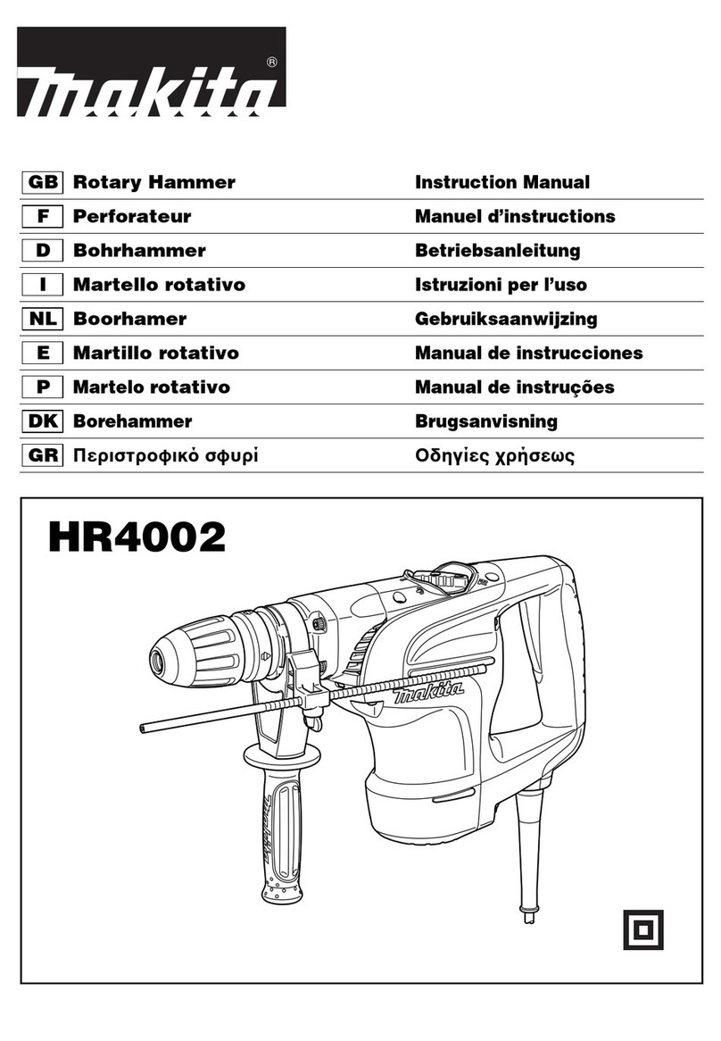
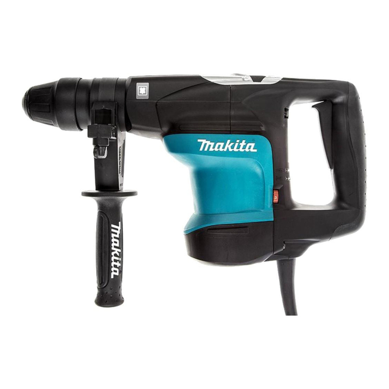
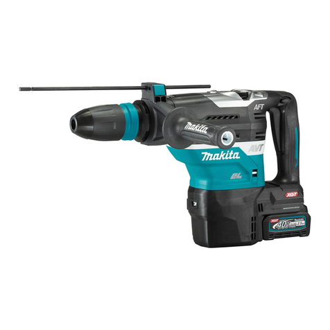
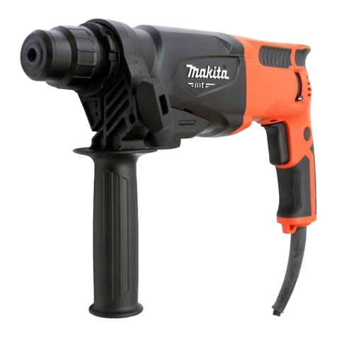
Makita HR5001C Manual

Voltage(V)
No load speed
Blows per minute
Bit type
Max.capacities
Net weight
Cord length
(Work : Concrete)
Current(A) Cycle(Hz) Continuous Rating(W) Max.Output(W)
Input Output
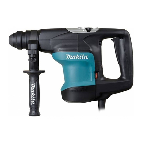
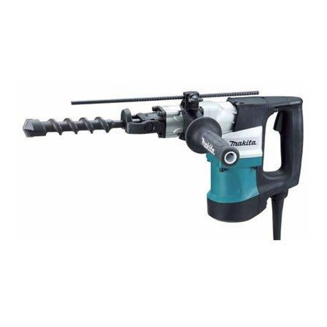
Model HR5001C is 50 mm rotary hammer for the SSDS-max bit
designed as the sister version the existing Model HR4000C.
Its brief benefits are;
*Can achive the highest efficiency in this class.
*Electrical speed control feature
Variable speed
Soft start
Steady speed
100
110
120
220
230
240
15
15
15
7.7
7.4
7.1
50/60
50/60
50/60
50/60
50/60
50/60
1450
1500
1500
1500
1500
1500
460
600
600
600
600
600
1400
1900
1900
1900
1900
1900
120 ~ 240rpm
1100 ~ 2150bpm
SDS-max. shank
Diameter of shank : 18 mm(11/16'')
T.C.T.Bit:50mm(2")
Core bit : 160 mm(6-5/16")
10Kg(22bs)
5m(16.4ft)
Grease Vessel ------------------1 pc.
Plastic Carrying Case --------1 pc.
Bar-type handle ---------------1 pc.
D-type handle -----------------1 pc.
T.C.T.Bit :19(3/4"), 20(15/16"), 21.5(7/8"), 22(7/8"), 25(1"), 28(1-1/8"), 32(1-3/8"), 35(1-3/8"), 38(1-1/2")
Bull point 280, 400 Cold chisel 25~280,25~400 Scaling chisel 50 Tile chisel 50
Clay Spade Core bit adapteer D-type side handle
Core bit : 20(15/16"), 30(1-3/16"), 35(1-3/8"), 40(1-9/16"), 45(1-3/4"), 54(2-1/8"), 65(2-9/16"),
79(1-1/8"), 105(4-1/8") , 118(4-5/8")
Grease Vessel(Bit grease,Hammer grease) Depth Gauge Safety Goggle
610
(24")
118 (4-5/8")
280
(11")
Rotations per minute
Models No.
Description
New Tool
TECHNICAL INFORMATION
1. Double insulated
2. See the sheets attached for more information
Models No.
Description
HR5001C
50mm Rotary Hammer
CONCEPTION AND MAIN APPLICATIONS
Specifications
Standard equipment
Optional accessories
Features and benefits

Push-to-strike system
Efficiency
All enclosure is made of resin.
Large change lever
For pointing job, you can use
this toolholding barrel
One touch chuck
D-type handle ( Standard accessory)
Bar-handle ( Standard accessorry)
Large model plastic case
(standard accessory)
Automatic cut-off
carbon brush
Large trigger
New torque limitter system
Lamp will light off,when
switch or power supply
cord becomes defective.
Lamp will light up for
indicating time for
replacement of
carbon brushes
Power supply cord or
switch can be easily
replaced.
Speed adjustable dial
*:#Same features as HR4000C
HR5001C
*
*
*
*
*
*
*
*
*
*
Even if the bit touches the electric wire
inside the wall,an electrical shock may
hardly hit on the operator.
The highest efficiency in this class.
Roller clutch system
(#HR4000C:Ball clutch system)
for coping with the higher power,
and for improvement of endurance.
No fatigue at finger after
long operation.
Easy to change opeation mode
between "Hammering only"
and "Rotation with hammerig"
Bit does not jump arround.
Efficiency and endurance
are improved.
without feeling heat from barrel
by resin cover
By just inserting,
the bit can be installed.
Both handles can be fixed at any angle and
at any positions back/forth on the barrel.
The D-type handle for hammering can be
swiveled at 8 positions back/forth.
Holding power required when torque limiter operating
Approx. 20 kgf
Makita #HR5001C
Approx. 29 kgf
Bosch #GBH10DC
600 mm(23-5/8") bit. can be
carried.
270mm 200mm
Carbon brushes can be
replaced without
remove the rear cover.
Longer life motor
The thicness of the commutator is
2 times of HR5000 .
The varnish is coated on the armature
against dust.
Light hammering or drilling
is easily performed
by setting lower speed.
by removing two screws
of handle cover.
It will light up about 8-hr
before the carbon brush are
worn out.
Lit during no defective.

Repair
(1) Removing Change lever ------------------------------ ------(Page 6 of 14)
(2) Install Change lever ------------------------------- ----------(Page 6 of 14)
(3) Replace the Armature ------------------------------- --------(Page 7 of 14)
(4) Disassembling the chuck --------------------------- -------(Page 8 of 14)
(5) Assembling the chuck ------------------------------- -------(Page 8 of 14)
(6) Removing Tool holderers ---------------------------------(Page 8 of 14)
(7) Disassembling tool holders ------------------------- -------(Page 9 of 14)
(8) Assembling the tool holder A and B ----------------- -----(Page 9 of 14)
(9) Taking out Cylinder 40 ----------------------------- --------(Page 9 of 14)
(10) Assembling Piston, Rod and Crank shaft -------------- -(Page 10 of 14)
(11) Assembling Fluoride ring 28 on Impact bolt ---------- (Page 10 of 14)
(12) Assembling several parts in Crank housing ----------- (Page 11 of 14)
(13) Inserting T ool holders -------------------------------------(Page 11 of 14)
(14) Assembling Torque limiter complete -------------------(Page 12 of 14)
(15) Lublication ----------------------------------------- --------(Page 13 of 14)

•Installing Change lever (same as HR4000C)
•Removing Change lever(same as HR4000C)
a. Set the change lever at neutral position, and slightly
hit the back side of the lock button using the resin
hammer to remove it.(See the figure 1.)
b. Insert Crank pin 4 of the change lever into the
hole of Change link. (See the figure 3)
Lock button
Change lever
Resin hammer
Neutral position
Figure 1
Figure 2 Figure 3
Note 1) Change lever should at the position of hammering-mode.
Note 2) Do not start the tool while the Change lever is not installed.
It may potentially lock and damage the parts inside the tool.
Change link Hole of the Change link
Hammering-mode
Change lever
a. Adjust Change link.(See the figure 2.)
to position the hole for Crank pin4 of Change lever.
(Crank pin 4 position)

a. Slide down Chuck cover and remove Tool
holder cap.(See the figure 4.)
b. Remove pan head screws, and then remove Crank
housing cover and Gear housing cover.(See the figure 4.)
c. Remove hex.socket head bolts and then remove
handle.(See the figure 5.)
d. Remove the connector.(See the figure 5.)
e. Remove the screw for holding the Fix rod, and then pull
out the Fix rod and the Pick up coil. (See the figure 6.)
Note 1) Pulling out the lead wire of Pick up coil without
removing the Fix rod may cause the disconnection.
Note 2) For Connector shown on the figure 5, be sure to
pull out Connector itself while holding Controller.
f. Pull out the 3 pieces of terminals
(white, black and red).(See the figure 7.)
g. Remove Rear cover and loosen the Hex.nut M8
while holding the Fan 90.(See the figure 6.)
h. Remove Fan 90 and rremove the 4 pieces
of hex.socket head bolts for holding the Crank
housing. (See the figure 6.)
Remove of Crank housing.
i. Strike the rear of armature shaft to remove
Gear housing and armature from the Motor
housing.
j. Use gear puller to remove the armature
shaft from Gear housing.
(See the figure 8.)
Tool holder cap
Chuck cover
Pan head screw
Gear housing cover
Crank housing cover
Figure 4
Figure 5
Controller
Black
Handle
Connector White
Hexagon-holed bolt :
6-piece
Hex.socket headbolt
Crank housing
Motor housing
Controller
Gear housing
Fan 90
Lead wire
Fix rod
Screw
Pick-up coil
Hex.nut M8
Rear cover Figure 6
k. To assemble the armature, place Ball bearing
6201 and the Oil seal 14 into Gear housing,then push
Armature into place.
(See the figure 9.)
Controller
Black
White Red
Repairing tool
1R-045
Gear housing
Armature
Figure 8
Ball bearing 6201 Gear housing
Oil seal 14 Apply the grease
Buckle plate Armature
Figure 9Figure 7
•Replacing Armature

¥Disassembling the chuck(See the figure 10.)
a. Remove Tool holder cap, Chuck cover and Crank housing cover.
b. Remove ring spring 25.
c. Remove Retaining ring WR-45.
To remove Ring spring 25 and the Retaining ring WR-45, using retaining ring pliers is recommended.
d. Remove Leaf spring 41 and pull aut pin 8.
Ring spring 25
Circle clip(shaft) WR-45
Tool holder
Leaf spring
pin 8
Cup washer 45 Chuck ring
Use care in direction.
Dent portion
Figure 10
Figure 11
Figure 13 Figure 14
Figure 12
Circle clip(shaft) WR-45
Repairing tool 1R-212
Chuck ring
Fit to the dent
portion.
Leaf spring
¥ Removing Tool holders
a. Plase the slotted driver at the dent portion on the external place of Seal case and slightly strike
it to remove the Seal case.(See the figure 13.)
b. Remove Retaining ring R-72 and then pull out Tool holder.
When difficult to pull out, insert the slotted driver into the elongation hole of Tool holder and
then hit slightly it.(See the figure 14.)
Tool holder
Seal case Retaining R-72
Tool holderA
¥Assembling the chuck (See the figure 10.)
Note ) Assemble the chuck in a way that the dent portion of the leaf spring can be securely positioned
at the dent portion on Chuck ring.
Elongation hole

a. Remove Retaining WR-50.
To remove Retaining WR-50, use retaining ring plier.
b. To disconnect the ball bearing 6910,use gear pullerwithsupport plate
(see the figure 15.)
Support plate
Gear puller
Tool holder A
Retaining WR-50
Ball bearing 6910
Figure 15
Figure 16
Figure 17
Note 1) When inserting Tool holder A, use care that O ring36 mounted on
tool holder A may not exceed the hole for holding the pin 10 of tool holder B.
(Reason : O ring 36 may be cut off.)
Note 2) O ring 36(Pn:213522*3) to be mounted on the Tool holder A is different
from the O ring 36(Pn:213510*0) to be mounted on Cylinder 40 and crank
cap.
O ring to be mounted on Tool holder A is the one of heat resistanse
and is coated with green paint for identification.
Adjust the position.
Hole for mounting the pin 10
Tool holder A
O ring 36
Tool holder B
Cylinder 40 is pressed into Crank housing.
To remove Cylinder 40, using gear puller 1R-213 is recommended.
(See the figure 17.)
If the repair tool IR-213 is not avarable,slightly hit
teh crank housing against the firm table several times
in a straight inte to remove cylinder 40.
Since strongly hitting it may damage of bent the crank
housing, please use the repair tool IR-213.
IR-213
To insert Tool holder A into Tool holder B, roughly maching holes for Pin 10.
Disassembling the tool holder
Assembling Tool holder A and B.(See the figure 16.)
Taking out cylinder 40

a. Set the 3 pieces of O ring 36 on Cylinder 40, and insert them into the crank housing.
b. Insert the piston until the rod hole is placed inside the crank room.
c. Insert crank shaft approaching Crank shaft to the rod hole.
Figure 18
Cylinder 40
O ring 36
Rod hole
Piston
Crank housing
Flat washer 56
Crank shaft
Figure 19
a. When Fluoride ring 28s are assenbled on the impact bolt, the fluoride ring 28 will
be extended and protruded over the groove.
b. Insert Impact bolt with Fluoride ring 28 into the repai ring tool 1R-214(Taper sleeve),
and hold about 10 seconds.
c. When inserting the impact bolt into Tool holder A, usecare not to pinch or tear off Fluoride ring 28.
Groove on the
impact bolt
Fluorocarbon resin ring 28
O ring
Edge face protruded
Taper sleeve After modification
Assembling Piston, Rod and Crank shaft(see the figure 18.)
Assembling Fluoride ring 28 on Impact bolt(Same as HR4000C. see the figure 19.)

a. Set the parts described below into the crank housing.(See the figure 20.)
b. To set the spiral bevel gear 41, use the tool holder without mounting the lock sleeve for smooth setting.(See the figure 21.)
•Striker(mounted with O ring 34)
•Washer 45
•Ring 45
•Flanged sleeve 22
•Ring 22
•Spiral bevel gear 41
•Compression spring 46
•Slide sleeve
•Rubber ring
Note ) Use care that the washer 45, Flanged sleeve 22, rubber ring 24, ring 22 and striker have each direction.
Figure 20
Ring 22
Rubber ring
Flanged sleeve
Slide sleeve Compression
spring 46 Striker
O ring 34
Spiral bevel
gear 41 Crank housing
Washer 45
Ring 45
Use care of each direction.
Figure 21
Figure 22
Figure 23
Tool holder Spiral bevel gear 41
a. Assemble Tool holder B and Spiral bevel gear 41,
matching the cams of both parts.(See the figure 23.)
b. Turn Spiral bevel gear 41 to match dent portions onthe can
with grooves on Crank housing. (see the figure 22.)
c. Match the cam on Lock sleeve A to the cam on Tool holder B.
(see the figure 23)
d. Match the flat portion of Lock sleeve A to the mounting side of Change
lever. fit the 6 protruded portions on Lock sleeveB to the 6 grooves on
Crank housing, and then insert the tool holder into Crank housing.
(see the figurt 23.)
12 dent portions
on the cam of the
spiral bevel gear 41
6 grooves on the
crank housing
Mounting side
of the change
lever
Tool holderA
6 protruded portions
on the lock sleeve B
Cam on the lock sleeve A
Cam on the tool holder B
Cam on the spiral
bevel gear 41
Flat portion of lock sleeve B
Assembling the tool holder
Inserting Tool holder(Same as HR4000C)

a. Assemble the ball bearing 6201, Flat washer 12(Outer dia. 24 mm)
and torque limiter complete into the spiral bevel gear 12. (See the figure 24.)
Note ) Use care not to miss the pin 4 for preventing
the round nut from turning.
Figure 24
Groove of change key
Change
key
Flat washer 12
(Outer dia. 28 mm)
Retaining ring S-12
Flat washer 12
(Outer dia. 24 mm)
Groove for retaining ring
Torque
limiter
complete
Round nut
Pin 4
Ball bearing 6201
Spiral bevel gear 12
Flat washer 12
(Outer dia. 24 mm)
Figure 25
Figure 26
b. Insert the flat washer 12(Outer dia. 24 mm)
and Retaining Rimg S-12 while setting the
two pieces of change keys into the key groove of
spiral bevel gear 12, and then insert
Flat washer 12(Outer dia. 28 mm) into
the groove of Change key.(See the figure 24.)
Change link
Slide plate
Compression spring 3
Guide pin 2
Groove of the change link
Ball bearing 608 2RS
Gear housing
Flat washer 12
(Outer dia. 28 mm)
d. Assemble slide plate, compression spring 3 and
guide pin 2 into the change link.(See the figure 26.)
e. Insert flat washer 12(Outer dia. 28 mm) into
the groove of the change link and then assemble
them on the ball bearing 608 2RS.(See the figure 26.)
c. Slide down the two pieces of change keys
into gutters of Spiral bevel gear 12 and
then insert Retaining ring S-12 int the groove
for retaining ring. (See the figures 24)
Make sure that Retaining ring S-12 has been
securely inserted in the groove.
Assembling the torque limiter(Same as HR4000C)

To prevent abrasion and overheating, please apply the
MAKITA grease R No.00 at the positions shown below.
a. O ring of striker
b. Inside of ring 45
c. Inner of slide sleeve
d. Outside and gear of Spiral bevel gear 41
Teeth
Inside of
slide sleeve Inside of
ring 45 Striker
O ring Outside
Spiral bevel
gear 41
e. O ring of piston and rod hole
Rod hole
O ring
f. Outer surface of impact bolt
Outer surface
of impact bolt
g. Between spiral bevel gear 12 and the torque limiter complete
Between Spiral
bevel gear 12 and
torque limiter complete
h. Lip of Oil seal 14 and oil seal 48
Lip
i. Needle bearing(Gear housing, Helical gear 20 complete)
Helical gear 20 complete
j. Each gear teeth
Needle bearing Gear housing Needle bearing
Lubication

(Page 14 of 14)
Switch
Power supply cord
P1
P2
Controller
Black
Black
Red
White
White
Orange
Orange
Brush holder
Connector Violet
Field
Connector
Brush holder
Wiring diagram
Other manuals for HR5001C
7
Table of contents
Other Makita Rotary Hammer manuals

Makita
Makita HR2455 User manual

Makita
Makita HR3520 User manual

Makita
Makita HR4001C User manual

Makita
Makita HR140D User manual

Makita
Makita HR2450FT Manual

Makita
Makita HR4001C User manual

Makita
Makita HR5201C User manual

Makita
Makita GRH06 User manual

Makita
Makita HR2010 Manual

Makita
Makita HR166D User manual

Makita
Makita HR2000 Manual

Makita
Makita HR3000C User manual

Makita
Makita HR3000C User manual

Makita
Makita HR3000C User manual

Makita
Makita HR4501C User manual

Makita
Makita HR1830 User manual
Makita
Makita HR1841F User manual

Makita
Makita HR2020 User manual

Makita
Makita HR2470 User manual

Makita
Makita HR166DSMJ User manual