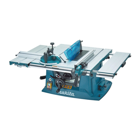
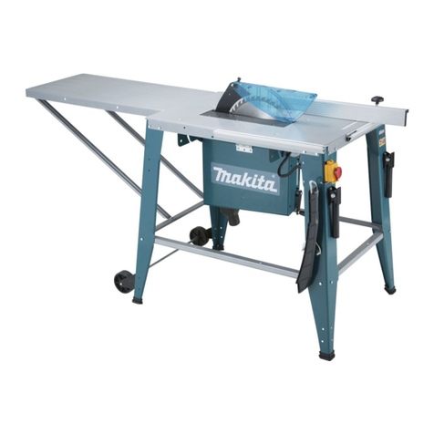
Makita 2704 User manual

2704
EN Table Saw INSTRUCTION MANUAL 9
ZHCN 台锯 使用说明书 17
ID Mesin Gergaji Meja PETUNJUK PENGGUNAAN 26
MS Gergaji Meja MANUAL ARAHAN 36
VI Máy Cưa Bàn Hoạt Động
Bằng Động Cơ Điện TÀI LIỆU HƯỚNG DẪN 46
TH 55

620 mm
1
525 mm
1
25 mm
2
12
1
1
2
1
12
3
12
Fig.1
Fig.2
Fig.3
Fig.4
Fig.5
Fig.6
Fig.7
Fig.8
2

(A)
(B)
90
90 45
45
1
ON OFF
1
1
1
1
1
1
2
Fig.9
Fig.10
Fig.11
Fig.12
Fig.13
Fig.14
Fig.15
Fig.16
3

2
1
2
1
1
2
1
32
12
3
45
12
1
2
3
1
2
2
3
1
Fig.17
Fig.18
Fig.19
Fig.20
Fig.21
Fig.22
Fig.23
Fig.24
4

1
2
1
2
3
4
5
4-5mm
2
1
1
3
2
1
B
A
1
1
2
3
4
Fig.25
Fig.26
Fig.27
Fig.28
Fig.29
Fig.30
Fig.31
Fig.32
5

12
3
4
1
2
120mm
300mm
130mm
50mm
6mm
300mm
130mm
100mm
50mm
9.5mm
50mm
8mm
1
2
34
Fig.36
9.5 mm
19 mm 120 mm
40 mm
140 mm
460 mm
1
1
Fig.33
Fig.34
Fig.35
Fig.37
Fig.38
6

1
1
1
2
12
34
1
3
2
1
23
Fig.39
Fig.40
Fig.41
Fig.42
Fig.43
Fig.44
Fig.45
Fig.46
7

1
12
Fig.47
Fig.48
Fig.49
Fig.50
8

9ENGLISH
ENGLISH (Original instructions)
SPECIFICATIONS
Model 2704
(for European countries) (for other than European
countries)
Arbor hole 30 mm 25 mm and 25.4 mm
Blade diameter 260 mm 255 mm / 260 mm
Max. cutting capacities 90° 93 mm 91 mm / 93 mm
45° 64 mm 63 mm / 64 mm
No load speed (min-1)4,800
Table size (L x W) (665 mm - 1,045 mm) x
(753 mm - 1,066 mm)
with sub tables (R) and (back)
567 mm x (753 mm - 1,066 mm)
with sub table (R)
Dimensions (L x W x H) with table(s) not extended 715 mm x 753 mm x 344 mm
with sub tables (R) and (back)
665 mm x 753 mm x 344 mm
with sub table (R)
Net weight 34.9 kg 29.5 kg
Safety class ./II
• Due to our continuing programme of research and development, the specications herein are subject to change
without notice.
• Specications may dier from country to country.
• Weight according to EPTA-Procedure 01/2003
Symbols
The following show the symbols used for the equip-
ment. Be sure that you understand their meaning before
use.
Read instruction manual.
DOUBLE INSULATION
Wear safety glasses.
Do not place hand or ngers close to the
blade.
Only for EU countries
Do not dispose of electric equipment
together with household waste material!
In observance of European Directive
2002/96/EC on waste electric and elec-
tronic equipment and its implementation
in accordance with national law, electric
equipment that have reached the end of
their life must be collected separately and
returned to an environmentally compatible
recycling facility.
Intended use
The tool is intended for cutting in wood.
Power supply
The tool should be connected only to a power supply
of the same voltage as indicated on the nameplate,
and can only be operated on single-phase AC supply.
They are double-insulated in accordance with European
Standard and can, therefore, also be used from sockets
without earth wire.
SAFETY INSTRUCTIONS
WARNING! When using electric tools, basic safety
precautions, including the following, should always
be followed to reduce the risk of re, electric shock
and personal injury. Read all these instructions
before operating this product and save these
instructions.
For safe operations:
1. Keep work area clean.
Cluttered areas and benches invite injuries.
2. Consider work area environment.
Do not expose power tools to rain. Do not use
power tools in damp or wet locations. Keep work
area well lit. Do not use power tools where there is
risk to cause re or explosion.
3. Guard against electric shock.
Avoid body contact with earthed or grounded sur-
faces (e.g. pipes, radiators, ranges, refrigerators).
4. Keep children away.
Do not let visitors touch the tool or extension cord.
All visitors should be kept away from work area.
5. Store idle tools.
When not in use, tools should be stored in a dry,
high or locked up place, out of reach of children.
6. Do not force the tool.
It will do the job better and safer at the rate for
which it was intended.
7. Use the right tool.
Do not force small tools or attachments to do
the job of a heavy duty tool. Do not use tools for
purposes not intended; for example, do not use
circular saws to cut tree limbs or logs.

10 ENGLISH
8. Dress properly.
Do not wear loose clothing or jewellery, they can
be caught in moving parts. Rubber gloves and
non-skid footwear are recommended when work-
ing outdoors. Wear protecting hair covering to
contain long hair.
9. Use safety glasses and hearing protection.
Also use face or dust mask if the cutting operation
is dusty.
10. Connect dust extraction equipment.
If devices are provided for the connection of dust
extraction and collection facilities ensure these are
connected and properly used.
11. Do not abuse the cord.
Never carry the tool by the cord or yank it to dis-
connect it from the socket. Keep the cord away
from heat, oil and sharp edges.
12. Secure work.
Use clamps or a vice to hold the work. It is safer
than using your hand and it frees both hands to
operate the tool.
13. Do not overreach.
Keep proper footing and balance at all times.
14. Maintain tools with care.
Keep cutting tools sharp and clean for better and
safer performance. Follow instructions for lubrica-
tion and changing accessories. Inspect tool cord
periodically and if damaged have it repaired by an
authorized service facility. Inspect extension cords
periodically and replace, if damaged. Keep han-
dles dry, clean and free from oil and grease.
15. Disconnect tools.
When not in use, before servicing and when
changing accessories such as blades, bits and
cutters.
16. Remove adjusting keys and wrenches.
Form the habit of checking to see that keys and
adjusting wrenches are removed from the tool
before turning it on.
17. Avoid unintentional starting.
Do not carry a plugged-in tool with a nger on the
switch. Ensure switch is o when plugging in.
18. Use outdoor extension leads.
When tool is used outdoors, use only extension
cords intended for outdoor use.
19. Stay alert.
Watch what you are doing. Use common sense.
Do not operate tool when you are tired.
20. Check damaged parts.
Before further use of the tool, a guard or other part
that is damaged should be carefully checked to
determine that it will operate properly and perform
its intended function. Check for alignment of mov-
ing parts, free running of moving parts, breakage
of parts, mounting and any other conditions that
may aect its operation. A guard or other part
that is damaged should be properly repaired or
replaced by an authorized service center unless
otherwise indicated in this instruction manual.
Have defective switches replaced by an autho-
rized service facility. Do not use the tool if the
switch does not turn it on and o.
21. Warning.
The use of any accessory or attachment, other
than those recommended in this instruction man-
ual or the catalog, may present a risk of personal
injury.
22. Have your tool repaired by a qualied person.
This electric tool is in accordance with the relevant
safety requirements. Repairs should only be car-
ried out by qualied persons using original spare
parts, otherwise this may result in considerable
danger to the user.
23. Use of power supply via an RCD with a rated
residual current of 30 mA or less is always
recommended.
ADDITIONAL SAFETY RULES FOR
TOOL
SAVE THESE INSTRUCTIONS.
1. Wear eye protection.
2. Do not use the tool in presence of ammable
liquids or gases.
3. NEVER use the tool with an abrasive cut-o
wheel installed.
4. Check the blade carefully for cracks or damage
before operation. Replace cracked or damaged
blade immediately.
5. Use only saw blades recommended by the
manufacturer and which conform to EN847-1,
and observe that the riving knife must not be
thicker than the width of the cut by the saw
blade and not thinner than the body of the
blade.
6. Always use accessories recommended in this
manual. Use of improper accessories such as
abrasive cut-o wheels may cause an injury.
7. Select the correct saw blade for the material to
be cut.
8. Do not use saw blades manufactured from
high speed steel.
9. To reduce the emitted noise, always be sure
that the blade is sharp and clean.
10. Use correctly sharpened saw blades. Observe
the maximum speed marked on the saw blade.
11. Clean the spindle, anges (especially the
installing surface) and hex nut before install-
ing the blade. Poor installation may cause
vibration/wobbling or slippage of the blade.
12. Use saw-blade guard and riving knife for every
operation for which it can be used, including
all through sawing operations. Always install
the blade guard following the instructions
out-lined in this manual. Through sawing oper-
ations are those in which the blade cuts com-
pletely through the workpiece as in ripping or
cross cutting. NEVER use the tool with a faulty
blade guard or secure the blade guard with a
rope, string, etc. Any irregular operation of the
blade guard should be corrected immediately.
13. Immediately reattach the guard and riving
knife after completing an operation which
requires removal of the guard.

11 ENGLISH
14. Do not cut metal objects such as nails and
screws. Inspect for and remove all nails,
screws and other foreign material from the
workpiece before operation.
15. Remove wrenches, cut-o pieces, etc. from the
table before the switch is turned on.
16. NEVER wear gloves during operation.
17. Keep hands out of the line of the saw blade.
18. NEVER stand or permit anyone else to stand in
line with the path of the saw blade.
19. Make sure the blade is not contacting the
riving knife or workpiece before the switch is
turned on.
20. Before using the tool on an actual workpiece,
let it run for a while. Watch for vibration or
wobbling that could indicate poor installation
or a poorly balanced blade.
21. The tool should not be used for slotting, rab-
betting or grooving.
22. Replace table insert when worn.
23. NEVER make any adjustments while tool is
running. Disconnect tool before making any
adjustments.
24. Use a push stick when required. Push sticks
MUST be used for ripping narrow workpieces
to keep your hands and ngers well away from
the blade.
25. Always store the push-stick when it is not in
use.
26. Pay particular attention to instructions for
reducing risk of KICKBACK. KICKBACK is
a sudden reaction to a pinched, bound or
misaligned saw blade. KICKBACK causes
the ejection of the workpiece from the tool
back towards the operator. KICKBACKS CAN
LEAD TO SERIOUS PERSONAL INJURY. Avoid
KICKBACKS by keeping the blade sharp, by
keeping the rip fence parallel to the blade, by
keeping the riving knife and blade guard in
place and operating properly, by not releasing
the workpiece until you have pushed it all the
way past the blade, and by not ripping a work-
piece that is twisted or warped or does not
have a straight edge to guide along the fence.
27. Do not perform any operation freehand.
Freehand means using your hands to support
or guide the workpiece, in lieu of a rip fence or
miter gauge.
28. NEVER reach around or over saw blade.
NEVER reach for a workpiece until the saw
blade has completely stopped.
29. Avoid abrupt, fast feeding. Feed as slowly as
possible when cutting hard workpieces. Do not
bend or twist workpiece while feeding. If you
stall or jam the blade in the workpiece, turn
the tool o immediately. Unplug the tool. Then
clear the jam.
30. NEVER remove cut-o pieces near the blade
or touch the blade guard while the blade is
running.
31. Knock out any loose knots from workpiece
BEFORE beginning to cut.
32. Do not abuse cord. Never yank cord to discon-
nect it from the receptacle. Keep cord away
from heat, oil, water and sharp edges.
33. Some dust created from operation contains
chemicals known to cause cancer, birth
defects or other reproductive harm. Some
examples of these chemicals are:
— lead from lead-based-painted material
and,
— arsenic and chromium from chemical-
ly-treated lumber.
— Your risk from these exposures varies,
depending on how often you do this
type of work. To reduce your exposure
to these chemicals: work in a well venti-
lated area and work with approved safety
equipment, such as those dust masks
that are specially designed to lter out
microscopic particles.
34. Connect the tool to a dust collecting device
when sawing.
35. The guard can be lifted during workpiece
setup and for ease of cleaning. Always make
sure that guard hood is down and at against
sawtable before plugging in the tool.
SAVE THESE INSTRUCTIONS.
INSTALLATION
Positioning table saw
► Fig.1: 1. Hole diameter 8 mm
► Fig.2: 1. 6 mm Std. washer 2. No.10 wood screw
40 mm min. length
► Fig.3: 1. 6 mm Std. washer 2. 6 mm Mounting bolt
& Nut tighten securely
Locate the table saw in a well lit and level area where
you can maintain good footing and balance. It should
be installed in an area that leaves enough room to
easily handle the size of your workpieces. The table
saw should be secured with four screws or bolts to the
work bench or table saw stand using the holes provided
in the bottom of the table saw. When securing the table
saw on the work bench, make sure that there is an
opening in the top of the work bench the same size as
the opening in the bottom of the table saw so the saw-
dust can drop through.
If during operation there is any tendency for the table
saw to tip over, slide or move, the work bench or table
saw stand should be secured to the oor.
Storing accessories
► Fig.4: 1. Miter gauge
► Fig.5: 1. Rip fence 2. Push stick
The miter gauge, blade and wrenches can be stored on
the left side of the base and the rip fence can be stored
at the right side of the base.

12 ENGLISH
FUNCTIONAL
DESCRIPTION
CAUTION:
• Always be sure that the tool is switched o and
unplugged before adjusting or checking function
on the tool.
Adjusting the depth of cut
► Fig.6: 1. Handle
The depth of cut may be adjusted by turning the handle.
Turn the handle clockwise to raise the blade or counter-
clockwise to lower it.
NOTE:
• Use a shallow depth setting when cutting thin
materials in order to obtain a cleaner cut.
Adjusting the bevel angle
► Fig.7: 1. Lock lever 2. Arrow pointer 3. Handwheel
Loosen the lock lever counterclockwise and turn the
handwheel until the desired angle (0° - 45°) is obtained.
The bevel angle is indicated by the arrow pointer.
After obtaining the desired angle, tighten the lock lever
clockwise to secure the adjustment.
CAUTION:
• After adjusting the bevel angle, be sure to
tighten the lock lever securely.
Adjusting positive stops
► Fig.8: 1. 90°Adjusting screw 2. 45°Adjusting screw
► Fig.9
The tool is equipped with positive stops at 90° and 45°
to the table surface. To check and adjust the positive
stops, proceed as follows:
Move the handwheel as far as possible by turning it.
Place a triangular rule on the table and check to see
if the blade is at 90° or 45° to the table surface. If the
blade is at an angle shown in Fig. A, turn the adjusting
screws clockwise; if it is at an angle shown in Fig. B,
turn the adjusting screws counterclockwise to adjust the
positive stops.
After adjusting the positive stops, set the blade at 90° to
the table surface. Then adjust the arrow pointer so that
its right edge is aligned to the 0° graduation.
► Fig.10: 1. Arrow pointer
Switch action
For the lever type switch
► Fig.11: 1. Switch
CAUTION:
• Before plugging in the tool, always be sure that
the tool is switched o.
To start the tool, raise the switch lever. To stop it, lower
the switch lever.
The hinged switch lever plate can be locked by passing
padlock through the hasp on the left hand side.
► Fig.12: 1. Padlock
For the button type switch
► Fig.13: 1. Switch
CAUTION:
• Before operation, make sure that the tool is
turned on and o.
To start the tool, press the ON ( I ) button.
To stop it, press the OFF ( O ) button.
Sub table (R)
► Fig.14: 1. Lever
► Fig.15: 1. Sub table (R)
This tool is provided with the sub table (R) on the right
side of the main table. To use the sub table (R), raise
both levers on the front right side, pull out the table (R)
fully and then lower the levers to secure it.
When using the sub table (R ), locate the scale plate
on the sub table after loosening the screw on it with
a screwdriver so that it becomes successive with the
scale plate on the main table.
► Fig.16: 1. Scale plate 2. Screw
Sub table (back)
(optional accessory for other than
European countries)
► Fig.17: 1. Sub table (back) 2. Screw
To use the sub table (back), loosen the screws on the
left and right hand sides under the table and pull it out
backwards to the desired length. At the desired length,
tighten the screw securely.
NOTE:
• When using the sub table (back) during use of
the rip fence, pull out the sub table (back) more
than 50 mm so that it does not hit against the
top end of the rip fence.
Sub table (L) (optional accessory)
► Fig.18: 1. Screw 2. Sub table (L)
Sub table (L) (optional accessory) can be installed on
the left side of the table to obtain wider space.
ASSEMBLY
CAUTION:
• Always be sure that the tool is switched o and
unplugged before carrying out any work on the
tool.
The tool is shipped from the factory with the saw blade
and blade guard not in the installed condition. Assemble
as follows:

13 ENGLISH
Installing or removing saw blade
CAUTION:
• Always be sure that the tool is switched o and
unplugged before installing or removing the
blade.
• Use only the Makita socket wrench provided to
install or remove the blade. Failure to do so may
result in overtightening or insucient tightening
of the hex bolt. This could cause an injury.
• Use the following saw blade. Do not use saw
blades which do not comply with the character-
istics specied in these instructions.
For Model Max. dia. Min. dia. Blade thickness Kerf
2704 260 mm 230 mm 1.8 mm or less 2 mm or more
CAUTION:
• Check the arbor hole diameter of the blade
before installing the blade. Always use the
correct ring for the arbor hole of the blade you
intend to use.
► Fig.19: 1. Oset wrench 2. Hex nut 3. Wrench
Remove the table insert on the table. Hold the outer
ange with the oset wrench and loosen the hex nut
counterclockwise with the wrench. Then remove the
outer ange.
Assemble the inner ange, ring, saw blade, outer ange
and hex nut onto the arbor, making sure that the teeth
of the blade are pointing down at the front of the table.
Always install the hex nut with its recessed side facing
the outer ange.
► Fig.20: 1. Inner ange 2. Ring 3. Saw blade
4. Outer ange 5. Hex nut
For all countries other than European
countries
CAUTION:
• The silver ring 25.4 mm in outer diameter is
factory-installed onto the spindle. The black ring
25 mm in outer diameter is included as standard
equipment. Before mounting the blade onto the
spindle, always be sure that the correct ring for
the arbor hole of the blade you intend to use is
installed onto the spindle.
For European countries
CAUTION:
• The ring 30 mm in outer diameter is factory-in-
stalled between the inner and outer anges.
• Keep the ange surface clean of dirt or other
adhering matter; it could cause blade slippage.
Be sure that the blade is installed so that
the teeth are aligned in the cutting (turning)
direction.
To secure the blade in place, hold the outer ange with
the oset wrench, then tighten the hex nut clockwise
with the wrench. BE SURE TO TIGHTEN THE HEX
NUT SECURELY.
► Fig.21: 1. Oset wrench 2. Wrench
CAUTION:
• Be sure to hold the hex nut carefully with the
wrench. If your grip should slip, the wrench may
come o the hex nut, and your hand could strike
the sharp blade edges.
Installing blade guard
► Fig.22: 1. Blade guard 2. Riving knife 3. Blade
guard mounting portion (stay)
► Fig.23: 1. Blade guard 2. Riving knife
CAUTION:
• Before installing the blade guard, adjust the
depth of cut to its maximum elevation.
For non-European type blade guard
Remove the center cover. Insert the riving knife into the
blade guard mounting portion (stay). Tighten the hex
bolts (A) with the provided wrench.
For European type blade guard
► Fig.24: 1. Riving knife 2. Blade guard 3. Lever
► Fig.25: 1. Blade guard 2. Riving knife
Remove the center cover. Insert the riving knife into the
blade guard mounting portion (stay). Tighten the hex
bolts (A) with the provided wrench.
Place the blade guard into the groove on the riving
knife. Secure the blade guard by pivoting the lever on
the blade guard.
For both European and non-
European type blade guards
The riving knife installing location is factory-adjusted so
that the blade and riving knife will be in a straight line.
However, if they are not in a straight line, loosen the hex
bolts (B) and adjust the blade guard mounting portion
(stay) so that the riving knife is aligned directly behind
the blade. Then tighten the hex bolts (B) to secure the
stay.
► Fig.26: 1. Blade 2. These two clearances should be
equal. 3. Riving knife 4. Hex bolts (B) 5. Hex
bolts (A)
CAUTION:
• If the blade and riving knife are not aligned prop-
erly, a dangerous pinching condition may result
during operation. Make sure they are properly
aligned. You could suer serious personal injury
while using the tool without a properly aligned
riving knife.
• NEVER make any adjustments while tool is
running. Disconnect the tool before making any
adjustments.
• Don't remove the riving knife.

14 ENGLISH
There must be a clearance of about 4 - 5 mm between
the riving knife and the blade teeth. Loosen the hex
bolts (A), adjust the riving knife accordingly and tighten
the hex bolts (A) securely. Attach the table insert on
the table, then check to see that the blade guard works
smoothly before cutting.
► Fig.27: 1. Riving knife 2. Blade guard
Installing and adjusting rip fence
► Fig.28: 1. Hook 2. Knob 3. Guide rail
1) Fit the hook on the tip of the rip fence into the far
guide rail on the table or sub table (R) and install and
push the rip fence forward so that the fence holder
engages with the nearmost guide rail.
To slide the rip fence on the guide rail sideways, pivot
the knob on the fence holder to the half way of its travel.
To secure the rip fence, pivot fully the knob on the fence
holder.
2) To slide the rip fence on the guide rail sideways,
return the knob on the fence holder fully without pulling
the lever on the knob.
3) To remove it, pull the lever on the knob and pivot the
knob fully forward while pulling the lever.
To check to be sure that the rip fence is parallel with
the blade, secure the rip fence 2 - 3 mm from the blade.
Raise the blade up to maximum elevation. Mark one
of the blade teeth with a crayon. Measure the distance
(A) and (B) between the rip fence and blade. Take both
measurements using the tooth marked with the crayon.
These two measurements should be identical. If the rip
fence is not parallel with the blade, proceed as follows:
► Fig.29: 1. Scale
► Fig.30: 1. Hex bolts
1. Position the rip fence in the sliding position.
2. Loosen the two hex bolts on the rip fence with the
hex wrench provided.
3. Adjust the rip fence until it becomes parallel with
the blade.
4. Pivot down the knob on the rip fence toward the
operator.
5. Tighten the two hex bolts on the rip fence.
► Fig.31
CAUTION:
• Be sure to adjust the rip fence so that it is par-
allel with the blade, or a dangerous kickback
condition may occur.
When the rip fence cannot be secured solidly, adjust it
according to the following procedure.
(1) Set the rip fence on the table and then pivot
the knob on the half way of its travel (moving
position). Tighten the screw (A) until the rip
fence is immobilized. Then loosen a 1/4 to
1/2 turn.
► Fig.32: 1. Rip fence 2. Released position 3. Moving
position 4. Lock position
► Fig.33: 1. Rip fence 2. Moving position 3. Screw (B)
4. Screw (A)
(2) Tighten the screw (B) fully and then loosen
about 2 full revolutions.
(3) Lock the rip fence by fully pivoting the knob
on the fence holder (lock position).
(4) Make sure that the rip fence can be installed
and removed in the original position
(released position).
(5) Make sure that the rip fence can be slid
smoothly with no wobble when the knob is
on half way of its travel.
CAUTION:
• Be careful not to tighten screws with more
than tightening amount specied in the above
instructions. Failure to do so may damage the
fastened parts.
Bring the rip fence up ush against the side of the
blade. Make sure that the guideline on the fence holder
points to the 0 graduation. If the guideline does not
point to the 0 graduation, loosen the screw on the scale
plate and adjust the scale plate.
► Fig.34: 1. Guideline 2. Screws
Connecting to vacuum cleaner
Cleaner operations can be performed by connecting the
tool to Makita vacuum cleaner or dust collector.
► Fig.35
OPERATION
CAUTION:
• Always use “work helpers” such as push sticks
and push blocks when there is a danger that
your hands or ngers will come close to the
blade.
• Always hold the workpiece rmly with the table
and the rip fence or miter gauge. Do not bend or
twist it while feeding. If the workpiece is bent or
twisted, dangerous kickbacks may occur.
• NEVER withdraw the workpiece while the blade
is running. If you must withdraw the workpiece
before completing a cut, rst switch the tool o
while holding the workpiece rmly. Wait until
the blade has come to a complete stop before
withdrawing the workpiece. Failure to do so may
cause dangerous kickbacks.
• NEVER remove cut-o material while the blade
is running.
• NEVER place your hands or ngers in the path
of the saw blade. Be especially careful with
bevel cuts.
• Always secure the rip fence rmly, or dangerous
kickbacks may occur.
• Always use “work helpers” such as push sticks
and push blocks when cutting small or narrow
workpieces.

15 ENGLISH
Work helpers
Push sticks, push blocks or auxiliary fence are types of
“work helpers”. Use them to make safe, sure cuts with-
out the need for the operator to contact the blade with
any part of the body.
Push block
► Fig.36: 1. Face/edge parallel 2. Handle 3. Wood
screw 4. Glue together
Use a 19 mm piece of plywood.
Handle should be in center of plywood piece. Fasten
with glue and wood screws as shown. Small piece
9.5 mm x 8 mm x 50 mm of wood must always be glued
to plywood to keep the blade from dulling if the operator
cuts into push block by mistake. (Never use nails in
push block.)
Auxiliary fence
► Fig.37: 1. Face/edge parallel
Make auxiliary fence from 9.5 mm and 19 mm plywood
pieces.
Wood facing (rip fence)
► Fig.38: 1. No. 10 wood screws (long enough to pen-
etrate halfway into facing)
A wood facing should be used for operations when the
blade comes close to the rip fence. Wood facing for
the rip fence should be the same size as the rip fence.
Make sure the bottom of facing is ush with the table
surface.
Ripping
CAUTION:
• When ripping, remove the miter gauge from the
table.
• When cutting long or large workpieces, always
provide adequate support behind the table.
DO NOT allow a long board to move or shift on
the table. This will cause the blade to bind and
increase the possibility of kickback and personal
injury. The support should be at the same height
as the table.
1. Adjust the depth of cut a bit higher than the thick-
ness of the workpiece.
► Fig.39
2. Position the rip fence to the desired width of rip
and lock in place by pivoting the grip. Before
ripping, make sure the rear end of the rip fence is
secured rmly. If it is not secured enough, follow
the procedures in the section titled “Installing and
adjusting rip fence”.
3. Turn the tool on and gently feed the workpiece into
the blade along with the rip fence.
(1) When the width of rip is 150 mm and wider,
carefully use your right hand to feed the
workpiece. Use your left hand to hold the
workpiece in position against the rip fence.
► Fig.40
(2) When the width of rip is 65 mm - 150 mm
wide, use the push stick to feed the
workpiece.
► Fig.41: 1. Push stick
(3) When the width of rip is narrower than
65 mm, the push stick cannot be used
because the push stick will strike the blade
guard. Use the auxiliary fence and push
block. Attach the auxiliary fence to the rip
fence with two “C” clamps.
► Fig.42: 1. Auxiliary fence
Feed the workpiece by hand until the end
is about 25 mm from the front edge of the
table. Continue to feed using the push block
on the top of the auxiliary fence until the cut
is complete.
► Fig.43: 1. Push block 2. Auxiliary fence
Cross cutting
CAUTION:
• When making a crosscut, remove the rip fence
from the table.
• When cutting long or large workpieces, always
provide adequate support to the sides of the
table. The support should be at the same height
as the table.
• Always keep hands away from path of blade.
Miter gauge
► Fig.44: 1. Cross cutting 2. Mitering 3. Bevel cutting
4. Compound mitering (angles)
Use the miter gauge for the 4 types of cutting shown in
the gure.
CAUTION:
• Secure the knob on the miter gauge carefully.
• Avoid creep of workpiece and gauge by rm
workholding arrangement, especially when
cutting at an angle.
• NEVER hold or grasp the intended “cut-o”
portion of the workpiece.
• Always adjust the distance between the end
of the miter gauge and the saw blade not to
exceed 15 mm.
Miter gauge positive stop
► Fig.45: 1. Knob 2. Small plate 3. Screw for positive
stop
Miter gauge is provided with positive stops at 90°,
45°right and left miter angles for quick setting of miter
angles.
To set the miter angle, loosen the knob on the miter
gauge.
Raise the small plate on the miter gauge for free setting.
Turn the miter gauge to the desired miter angle. Return
the small plate on the miter gauge to the original posi-
tion and tighten the knob clockwise securely.

16 ENGLISH
Use of miter gauge
► Fig.46: 1. Groove 2. Miter gauge 3. Knob
Slide the miter gauge into the thick grooves in the table.
Loosen the knob on the gauge and align to desired
angle (0° to 60°). Bring stock ush up against fence and
feed gently forward into the blade.
Auxiliary wood facing (miter gauge)
► Fig.47
To prevent a long board from wobbling, t the miter
gauge with an auxiliary fence board. Fasten with bolts/
nuts after drilling holes, but fasteners must not protrude
from the face board.
Carrying tool
► Fig.48
Make sure that the tool is unplugged.
Carry the tool by holding the tool part shown in the
gure.
CAUTION:
• Always secure all moving portions before carry-
ing the tool.
• Always make sure that the blade guard is
installed in place before the carrying the tool.
MAINTENANCE
CAUTION:
• Always be sure that the tool is switched o and
unplugged before attempting to perform inspec-
tion or maintenance.
• Never use gasoline, benzine, thinner, alcohol
or the like. Discoloration, deformation or cracks
may result.
Cleaning
Clean out sawdust and chips from time to time.
Carefully clean the blade guard and moving parts inside
the table saw.
Lubrication
To keep the table saw in tip-top running condition, and
to assure maximum service life, oil or grease the mov-
ing parts and rotating parts from time to time.
Lubrication places:
• Threaded shaft to elevate the blade
• Hinge to rotate the frame
• Elevation guide shafts on motor
• Gear to elevate the blade
• Guide rails for the rip fence
• Shaft of the sub table (R) locking levers
• Sliding part of the sub table (R)
Replacing carbon brushes
► Fig.49: 1. Limit mark
Check the carbon brushes regularly.
Replace them when they wear down to the limit mark.
Keep the carbon brushes clean and free to slip in the
holders. Both carbon brushes should be replaced at the
same time. Use only identical carbon brushes.
Use a screwdriver to remove the brush holder caps. To
replace the carbon brushes, remove the blade guard
and blade and then loosen the lock lever, tilt the saw
head and secure it at 45° bevel angle. Carefully lay the
tool on itself backward. Then loosen the brush holder
cap. Remove the worn carbon brushes, insert the new
ones and secure the brush holder caps.
► Fig.50: 1. Brush holder cap 2. Screwdriver
To maintain product SAFETY and RELIABILITY, repairs,
any other maintenance or adjustment should be per-
formed by Makita Authorized Service Centers, always
using Makita replacement parts.
OPTIONAL
ACCESSORIES
CAUTION:
• These accessories or attachments are recom-
mended for use with your Makita tool specied
in this manual. The use of any other accessories
or attachments might present a risk of injury to
persons. Only use accessory or attachment for
its stated purpose.
If you need any assistance for more details regard-
ing these accessories, ask your local Makita Service
Center.
Table stand set (accessory)
Refer to the instruction manual for table saw stand
that is provided with the table saw stand as an optional
accessory.
• Steel & Carbide-tipped saw blades
• Sub table ( L)
• Sub table ( back)
• Rip fence
• Miter gauge
• Oset wrench 13-22
• Wrench 19
• Hex wrench 5
• Joint ( for connecting to dust collector )
• Auxiliary plate
• Stand set
• Sliding guide
NOTE: Some items in the list may be included in the
tool package as standard accessories. They may
dier from country to country.

17
中文简体
中文简体 (原本)
规格
型号 2704
(用于欧洲国家) (用于非欧洲国家)
轴孔 30 mm 25 mm和25.4 mm
锯片直径 260 mm 255 mm / 260 mm
最大切
割能力
90°93 mm 91 mm / 93 mm
45°64 mm 63 mm / 64 mm
空载速度(/min)4,800
台面尺寸(长×宽) (665 mm至1,045 mm) x
(753 mm至1,066 mm)
含副台面(R)和(背面)
567 mm x (753 mm至1,066 mm)
含副台面(R)
尺寸(长x宽x高)
(台面未展开)
715 mm x 753 mm x 344 mm
含副台面(R)和(背面)
665 mm x 753 mm x 344 mm
含副台面(R)
净重 34.9 kg 29.5 kg
安全等级 ./II
• 由于持续的研发计划,我们保留变更规格不另行通知之权利。
• 规格可能因销往国家之不同而异。
• 重量符合EPTA-Procedure 01/2003
符号
以下显示本工具使用的符号。在使用工具之
前请务必理解其含义。
阅读使用说明书。
II类工具
佩带安全眼镜。
请勿将手或手指靠近锯片。
仅限于欧盟国家
请勿将电气设备与家庭普通
废弃物一同丢弃!
请务必遵守欧洲关于废弃电
子电气设备的2002/96/EC指
令,根据法律法规执行。达
到使用寿命的电气设备必须
分类回收至符合环境保护规
定的再循环机构。
用途
本工具用于切割木材。
电源
本工具只可连接电压与铭牌所示电压相同的
电源,且仅可使用单相交流电源。本工具根
据欧洲标准达到双重绝缘,因此也可用于不
带接地线的插座。
安全注意事项
警告!使用电动工具时,应始终遵守基本安
全注意事项(包括以下内容),以降低火
灾、触电和人身伤害风险。操作本产品前,
请阅读这些注意事项并请保留此说明书。
为进行安全操作:
1. 保持工作区域清洁。
工作区域和工作台混乱可能导致人身伤
害。
2. 注意工作区域环境。
请勿将电动工具暴露在雨水中。请勿将
电动工具暴露在潮湿的环境中。保持工
作区域照明情况良好。请勿在有火灾或
爆炸风险的地点使用电动工具。
3. 防止触电。
请避免与接地的表面(如管子、散热器、
炉灶和冰箱等)进行身体接触。

18
中文简体
4. 保持儿童远离。
不要让访问者触摸工具或延长线。所有
访问者必须保持远离工作区域。
5. 存放闲置工具。
不使用时,请将本工具放置在干燥的高
处或加锁位置,避免儿童接触。
6. 不要强力按压工具。
使用工具时不可超出其设计额定值,这
样才能更好、更安全地完成作业。
7. 使用正确的工具。
不要使用小型工具或装置来进行重型工
具的工作。不要将工具用于设计用途以
外的用途,例如,不要使用电动圆锯切
割树枝或原木。
8. 着装适当。
请勿穿着宽松的衣服或佩戴首饰,其可
能会被卷入运动部件。在室外工作时,
建议您穿戴橡胶手套和防滑鞋。佩带保
护头盔来保护长发。
9. 请使用安全眼镜和护耳装置。
如果切割操作灰尘较多,还请使用面罩
或防尘面罩。
10. 连接除尘设备。
如果提供了与除尘和集尘设备连接用的
装置,请确保将其正确连接和使用。
11. 请勿不当使用导线。
切勿拖着导线移动工具,或拉导线拔出
插座。避免使导线受热、沾染油脂和碰
到尖锐的边缘。
12. 安全工作。
请使用夹具或夹钳来固定工件。这要比
用手固定更安全有效,并可解放双手来
操作工具。
13. 操作时手不要伸得太长。
操作时请双脚站稳,始终保持平衡。
14. 小心保养工具。
保持切割工具锋利和清洁,以提高其性
能和安全性。根据说明进行润滑和更换
附件。定期检查工具导线,如有损坏,
请交由授权服务机构进行维修。定期检
查延长线,如有损坏请进行更换。保持
把手干燥、清洁,无油污和润滑脂。
15. 断开工具电源。
不使用时,维修前或更换锯片、起子头
和切割机等附件时请断开电源。
16. 取下调节钥匙和扳手。
养成在开启工具前检查钥匙和调节扳手
是否已从工具上取下的习惯。
17. 避免意外启动。
请勿在将手指放在开关上的情况下搬运
已插电工具。插入电源时请确保开关已
关闭。
18. 使用室外延长线。
在室外使用工具时,仅可使用设计用于
室外的延长线。
19. 保持警惕。
注意您的操作。请运用常识。疲劳时请
勿操作工具。
20. 检查受损部件。
在进一步使用工具之前,应仔细检查保
护罩或其他部件有无损坏,以确定工具
是否可以正常运转。检查运动部件是否
对齐或运动自如、部件是否破损、安装
是否妥当以及其他可能会影响工具运行
的情况。除非本手册另有声明,否则应
对受损保护罩或其他部件进行修复或由
授权维修中心进行更换。失灵的开关由
授权的维修机构进行更换。如果工具的
开关无法使工具开启和关闭,则请勿使
用该工具。
21. 警告。
除本手册或目录中推荐的附件或装置外,
使用任何其他附件或装置都可能存在人
身伤害风险。
22. 将工具交由有资格的人员维修。
本电动工具符合相关安全要求。维修仅
可由有资格的人员使用原装备件进行,
否则可能会给用户造成巨大的危险。
23. 始终建议通过额定剩余电流为30 mA或
以下的RCD来使用电源。
工具的补充安全规则
请保留此说明书。
1. 请佩戴安全眼镜。
2. 请勿在易燃液体或气体附近使用工具。
3. 请勿使用安装有切割砂轮的工具。
4. 操作之前,请仔细检查锯片上是否有裂
缝或损坏。应立即更换有裂缝或损坏的
锯片。
5. 仅可以使用制造商推荐的和符合EN847-1
的锯片,并注意劈刀的厚度不得超过锯片
的切割宽度并且不得比锯片薄。
6. 请务必使用本说明书中建议的附件。使
用切割砂轮等不适用的附件可能会导致
人身伤害。
7. 为要切割的材料选择正确的锯片。
8. 请勿使用高速钢制造的锯片。

19
中文简体
9. 为了降低发出的噪音,请务必确保锯片
锋利和清洁。
10. 使用正确打磨的锯片。请注意锯片上标
出的最大速度。
11. 安装锯片之前,请清洁主轴、法兰(特
别是安装表面)和六角螺栓。安装不良
可能会导致锯片振动/摇摆或滑动。
12. 进行可使用锯片进行的每一项操作时
(包括所有直锯操作),应使用锯片保
护罩和劈刀。安装锯片保护罩时,务必
遵循本手册中的指示。直锯操作指同切
锯或横切一样,锯片完全切穿工件的操
作。切勿使用锯片保护罩故障的工具或
用链绳和线绳等固定锯片。应立即纠正
对于锯片保护罩的任何违规操作。
13. 拆下保护罩并完成操作后,因立即装回
保护罩和劈刀。
14. 请勿切割钉子和螺丝等金属物品。操作
之前请检查工件上是否有钉子、螺丝和
其他异物并将其清除。
15. 打开开关前,应从台面上移除扳手和切
掉的小块等。
16. 作业期间,切勿佩戴手套。
17. 请勿将手放在锯片移动路线上。
18. 请勿与锯片移动路线成一直线站立或允
许他人与锯片移动路线成一直线站立。
19. 打开开关前,请确认锯片未与劈刀或工
件接触。
20. 在实际的工件上使用工具之前,请先让
工具空转片刻。请注意,振动或摇摆可
能表示安装不当或锯片不平衡。
21. 该工具不能用于打孔、槽刨或开槽。
22. 台面嵌板磨损时应进行更换。
23. 工具旋转期间切勿进行任何调节。进行
调节前请断开工具连接。
24. 必要时应使用推杆。切锯较窄的工件时,
应使用推杆,使手和手指远离锯片。
25. 不使用推杆时请将其存放到位。
26. 应特别注意降低反弹危险的说明。反弹
是锯片收缩、卡滞或方向偏离时突然产
生的反作用力。反弹会导致工件从工具
上弹回到操作者所在位置。反弹会导致
严重的人身伤害。为了避免反弹,请保
持锯片锋利,切锯导板与锯片平行,劈
刀和锯片保护罩处于正确的位置并工作
正常,在将工件完全推过锯片之前请勿
松开工件,不要切割扭曲或弯曲的工件
或没有直边可引导的工件。
27. 请勿徒手执行任何操作。徒手是指用您
的手支撑或引导工件,而不是用切锯导
板或斜接规。
28. 切勿触碰锯片周围或锯片之上。锯片完
全停止前切勿触碰工件。
29. 避免突然快速地馈送。切割较硬的工件
时,请尽可能慢地进行馈送。馈送期
间,请勿弯曲或扭曲工件。如果锯片在
工件中停转或卡住,请立即关闭工具。
拔下工具的电源插头。然后取出卡住的
锯片。
30. 切勿在锯片旋转的情况下移除锯片附近
切掉的小块或触碰锯片保护罩。
31. 开始切割之前,将工件上松动的结头敲
掉。
32. 请勿不当使用导线。切勿拉导线拔出插
座。避免导线受热、沾染油脂及水和碰
到尖锐的边缘。
33. 由操作所产生的某些灰尘中含有能够导
致癌症、新生儿缺陷或其他生殖危害的
化学物质。例如,有以下这些化学物质:
— 含铅油漆材料中的铅,
— 经化学处理的木材中的砷和铬。
— 根据您进行该类型作业的频率,您暴
露于这些化学物质的危险程度有所不
同。为尽量避免受到这些化学物质的
影响:请保持工作区域通风良好,并
使用认可的安全设备,如专门用于过
滤精细微粒的防尘面罩等。
34. 切割时请将工具连接至集尘设备。
35. 设置工件时可提起保护罩,便于清洁。
插入工具之前,务必确保保护罩向下且
平贴锯台。
请保留此说明书。

20
中文简体
安装
调节台锯位置
►图片1: 1. 8 mm内孔直径
►图片2: 1. 6 mm标准挡圈 2. 10号木螺丝
(最小长度:40 mm)
►图片3: 1. 6 mm标准挡圈 2. 6 mm安装螺
栓和螺母拧紧
将台锯置于照明情况良好并可保持立足稳固
及身体平衡的平坦区域。应将工具安装在剩
余空间便于处理工件尺寸的区域。应使用4
颗螺丝或螺栓,通过台锯底部的孔将台锯固
定至工作台或台锯支件上。将台锯固定至工
作台上时,确保工作台上的开孔尺寸与台锯
底部的开孔尺寸相同,以便锯屑落下。
操作期间,如有台锯翻倒、滑动或移动的趋
势,应将工作台或台锯支件固定至地面。
存放附件
►图片4: 1. 斜接规
►图片5: 1. 切锯导板 2. 推杆
斜接规、锯片和扳手可存放在基座的左侧,
切锯导板可存放在基座的右侧。
功能描述
小心:
• 在调节或检查工具功能之前,请务必
关闭工具电源开关并拔下电源插头。
调节切割深度
►图片6: 1. 把手
可通过转动把手来调节切割深度。顺时针转
动把手以升起锯片或逆时针转动把手以降下
锯片。
注:
• 在切割较薄的材料时,请使用较浅的切
割深度设置,使切割更干净。
调节斜切角度
►图片7: 1. 锁定杆 2. 箭头状指针 3. 手轮
逆时针拧松锁定杆并转动手轮直至达到所需
的角度(0°至45°)。由箭头状指针指示斜
切角度。
达到所需的角度后,顺时针拧紧锁定杆以紧
固调节。
小心:
• 调节斜切角度后,务必拧紧锁定杆。
调节前挡块
►图片8: 1. 90°调节螺丝 2. 45°调节螺丝
►图片9
本工具配备有前挡块,分别安装在台面的90°
和45°位置处。要检查和调节前挡块,请执行
以下操作:
旋转手轮,最大程度地移动手轮。将三角规
放在台面上,检查锯片是否位于台面的90°
和45°位置处。如果锯片位于图A所示的角度
处,顺时针转动调节螺丝;如果锯片位于图
B所示的位置处,则逆时针转动调节螺丝以
调节前挡块。
调节前挡块后,将锯片设置在台面的90°位
置处。然后,调节箭头状指针,使其右边缘
与刻度0°对齐。
►图片10: 1. 箭头状指针
开关操作
对于杆型开关
►图片11: 1. 开关
小心:
• 插上工具电源之前,请确认工具电源已
关闭。
启动工具时,抬起开关柄。降下开关柄可停
止工具。
铰链开关柄板可通过将挂锁穿过左侧的搭扣
进行锁定。
►图片12: 1. 挂锁
对于按钮型开关
►图片13: 1. 开关
小心:
• 操作之前,请务必将工具开启再关闭。
要启动工具时,请按ON(I)按钮。
要停止工具时,请按OFF(O)按钮。
副台面(R)
►图片14: 1. 杆
►图片15: 1. 副台面(R)
本工具的主台面右侧安装有副台面(R)。要
使用副台面(R),抬起右前侧的两个杆,拉
出台面(R),然后降下杆进行固定。
Other manuals for 2704
11
Table of contents
Languages:
Other Makita Saw manuals

Makita
Makita M2300 User manual

Makita
Makita 5704R User manual

Makita
Makita MLT100 User manual

Makita
Makita DLS110 User manual

Makita
Makita LS0714 User manual

Makita
Makita 5603R User manual

Makita
Makita LS1221 User manual

Makita
Makita BJR181 User manual

Makita
Makita LS1440 User manual

Makita
Makita 5007NB User manual

Makita
Makita 5604R User manual

Makita
Makita LB1200F User manual

Makita
Makita LS1040 User manual

Makita
Makita M583 User manual

Makita
Makita 2107F User manual

Makita
Makita LS711D User manual

Makita
Makita JR3050T User manual

Makita
Makita 5901B User manual

Makita
Makita 5820 User manual

Makita
Makita SP6000 User manual