Makita EM2600U User guide

Original Instruction Manual
Instructions d’emploi d’origine
Originalbetriebsanleitung
Manuale di istruzioni originale
Originele gebruiksaanwijzing
Instrucciones de manejo originales
Instruções de serviço original
Original brugsanvisning
Πρωτότυπο εγχειρίδιο οδηγιών
Orijinal Kullanım Kılavuzu
Important:
Read this instruction manual carefully before putting the brush cutter/string trimmer into operation and strictly observe the safety regulations!
Preserve instruction manual carefully!
Important :
Veuillez lire attentivement ce mode d’emploi avant d’utiliser la débroussailleuse thermique, et observez strictement les consignes de sécurité !
Veillez à conservez ce manuel d’instructions !
Wichtig:
Lesen Sie vor Verwendung der Motorsense/des Motor Rasentrimmers diese Bedienungsanleitung aufmerksam durch und halten Sie die
Sicherheitsregeln strikt ein!
Bewahren Sie diese Betriebsanleitung sorgfältig auf!
Importante:
Leggere attentamente il presente manuale di istruzioni prima di mettere in funzione il decespugliatore/tagliabordi e rispettare rigorosamente le
normative sulla sicurezza.
Conservare con cura il manuale di istruzioni.
Belangrijk:
Lees deze gebruiksaanwijzing aandachtig door voordat u de bosmaaier/graskantmaaier in gebruik neemt en houdt u te allen tijde aan de
veiligheidsinstructies!
Bewaar deze gebruiksaanwijzing zorgvuldig!
Importante:
Lea atentamente este manual de instrucciones antes de utilizar la desbrozadora y cumpla estrictamente la normativa de seguridad.
Conserve el manual de instrucciones con cuidado.
Importante:
Leia cuidadosamente este manual de instruções antes de utilizar a roçadeira a gasolina e cumpra todas as normas de segurança!
Guarde este manual de instruções num local seguro!
Vigtigt:
Læs denne brugsanvisning omhyggeligt igennem inden du anvender den buskrydderen/trådtrimmeren og overhold sikkerhedsregulativerne til
mindste detalje!
Gem denne brugsanvisning omhyggeligt!
Σημαντικό:
∆ιαβάστε αυτό το εγχειρίδιο οδηγιών προσεκτικά πριν θέσετε σε λειτουργία το βενζινοκίνητο θαμνοκοπτικό/χλοοκοπτικό και τηρήστε με
ακρίβεια τους κανονισμούς ασφαλείας!
∆ιατηρήστε με προσοχή το εγχειρίδιο οδηγιών!
Önemli:
Yan tırpanı/misinalıyan tırpanıkullanmaya başlamadan önce bu kullanım kılavuzunu dikkatlice okuyun ve güvenlik talimatlarınıharfiyen takip
edin!
Kullanım kılavuzunu dikkatlice saklayın!
EM2600U EM2600L

2
Thank you for purchasing this MAKITA brush cutter/string trimmer. MAKITA
brush cutters/string trimmers are developed as a product of our many years of
knowledge, experience, and a detailed development programme.
Please read this booklet thoroughly to ensure you gain the best possible
performance and outstanding results that your MAKITA brush cutter/string
trimmer can provide.
You need to note the following symbols when reading the instructions manual.
Symbols
Read instruction Manual Wear eye and ear protection
(for string trimmer only)
Take Particular care and Attention Wear protective helmet, eye and ear protection
(for brush cutter only)
Forbidden Do not use metal blades
(for string trimmer only)
Keep your distance Maximum permissible tool speed
Flying object hazard Hot surfaces - Burns to fingers or hands
No Smoking Fuel and oil mixture
No open flames Engine-Manual start
Protective gloves must be worn Emergency stop
Kickback First Aid
Keep the area of operation clear of all
persons and animals ON/START
Wear sturdy boots with nonslip soles. Steel-
toed safety boots are recommended. OFF/STOP
START
Table of Contents Page
Symbols ........................................................................ 2
Safety instructions......................................................... 3
Technical data............................................................... 7
Names of parts.............................................................. 8
Mounting the handle ..................................................... 9
Mounting the protector ................................................ 10
Mounting the cutter blade/nylon cutting head ............. 11
Fuel/Refuelling ............................................................ 12
Correct handling.......................................................... 13
Important operating points/stopping the cutter/
trimmer........................................................................ 13
Resharpening the cutting tool ..................................... 15
Servicing instructions .................................................. 17
Storage ....................................................................... 19
English

3
General Instructions
– To ensure correct operation, make sure that you read and fully understand this
instruction manual to familiarise yourself with how to use the brush cutter/
string trimmer. Using this equipment without understanding how to operate it
correctly may result in serious injury to yourself or others.
– Only lend the brush cutter/string trimmer to people who have proved
experienced with brush cutter/string trimmers. Always lend them this
instruction manual at the same time.
– If this is your first time using an engine powered cutter, consult your dealer for
basic instructions.
– Children and young persons aged under 18 years must not be allowed to
operate the brush cutter/string trimmer. Persons over the age of 16 years may
use the device for training purposes, only whilst under supervision of a
qualified trainer.
– Use brush cutter/string trimmers with the utmost care and attention.
– Only operate the brush cutter/string trimmer if you are in good physical
condition. Perform all work calmly and carefully. Users must accept
responsibility for those around them.
– Never use the brush cutter/string trimmer after consumption of alcohol or
medicines, or if you are feeling tired or ill.
WARNING: This machine produces an electromagnetic field during operation.
This field may under some circumstances interfere with active or passive
medical implants. To reduce the risk of serious or fatal injury, we recommend
persons with medical implants to consult their physician and the medical implant
manufacturer before operating this machine.
Intended use of the equipment
– The brush cutter/string trimmer is only intended for cutting grass, weeds, bush
and other such undergrowth, and should not be used for any other purpose
such as edging or hedge cutting as this may cause injury.
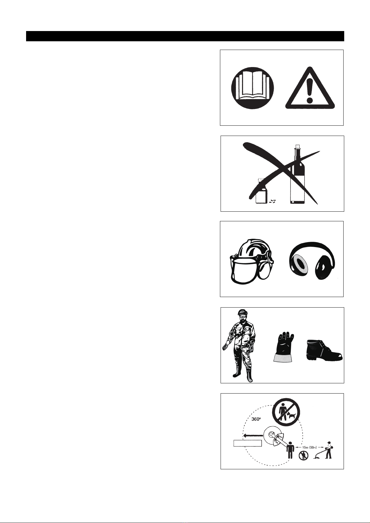
Personal protective equipment
– Always wear clothing that is both functional and appropriate to your work, i.e.
tight-fitting, but not so tight as to cause uncomfortable movement. Do not wear
either jewelry or clothing which could become entangled with bushes or
shrubs.
– In order to avoid head, eye, hand, or foot injuries, as well as to protect your
hearing during operation, the following protective equipment and protective
clothing must be used while using the brush cutter/string trimmer.
– Always wear a helmet where there is a risk of falling objects. The protective
helmet (1) is to be checked at regular intervals for damage and is to be
replaced at the latest after 5 years. Use only approved protective helmets.
– The visor (2) of the helmet (or alternatively goggles) protects the face from
flying debris and stones. During operation of the brush cutter/string trimmer,
always wear goggles or a visor to prevent eye injuries.
– Wear adequate noise protection equipment to avoid hearing impairment (ear
muffs (3), ear plugs etc.).
– Work overalls (4) protect against flying stones and debris.
We strongly recommend that you wear work overalls.
– Special gloves (5) made of thick leather are part of the prescribed equipment
and must always be worn during operation of the brush cutter/string trimmer.
– When using the brush cutter/string trimmer, always wear sturdy shoes (6) with
a non-slip sole. Such shoes protect against injuries and ensure good footing.
Residual risks
– Even when the machine is used as prescribed it is not possible to eliminate all
residual risk factors. The following hazards may arise in connection with the
machine’s construction and design:
1. Damage to lungs if an effective dust mask is not worn.
2. Damage to hearing if effective hearing protection is not worn.
3. Damages to health resulting from vibration emission if the machine is being
used over longer period of time or not adequately managed and properly
maintained.
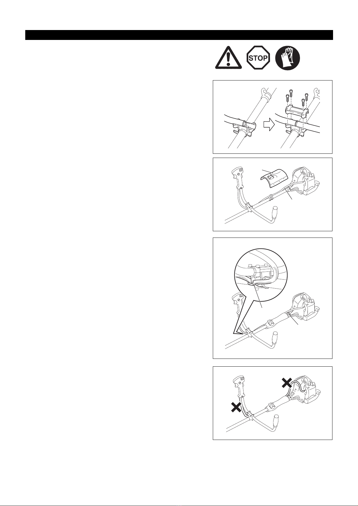
Starting the brush cutter
– Make sure that there are no children or other people within a working range of
15 meters (50ft), also pay attention to any animals in the working vicinity.
– Before use, always check that the brush cutter/string trimmer is safe for
operation:
Check that the cutting tool is secure, that the control lever can be operated
easily, and that the control lever lock is functioning correctly.
– Rotation of the cutting tool during idling is prohibited. Check with your dealer if
you think the equipment may need adjusting. Check to make sure that the
handles are clean and dry, and that the start/stop switch is functioning
correctly.
Safety instructions
Diagram
15 meters
(1)
(3)
(2)
(4)
(5) (6)

4
– Start the brush cutter/string trimmer only in accordance with the instructions.
Do not use any other methods to start the engine!
– Only use the brush cutter/string trimmer and tools for the specified purposes.
– Only start the brush cutter/string trimmer engine after the equipment is fully
assembled. Do not operate the equipment until all of the appropriate
accessories are attached!
– Before starting, make sure that the cutting tool is not in contact with hard objects
such as branches, stones etc. as the cutting tool will rotate when starting.
– Switch off the engine immediately if any type of engine problem occurs.
– Should the cutting tool hit stones or other hard objects, immediately switch off
the engine and inspect the cutting tool.
– Inspect the cutting tool at short regular intervals for damage (inspect for
hairline cracks using the tapping test).
– Only operate the brush cutter/string trimmer after attaching and adjusting the
shoulder strap to the correct length. The shoulder strap must be adjusted to
the user’s size and fastened to prevent fatigue during operation of the
equipment. Never hold the cutter with one hand during operation.
– During operation, always hold the brush cutter/string trimmer with both hands.
Always ensure you are on safe footing.
– Operate the brush cutter/string trimmer in such a manner as to avoid
inhalation of the exhaust gases. Never run the engine in an enclosed space
such as inside a room (risk of gas poisoning). Carbon monoxide is an odorless
gas.
– Always switch off the engine when resting, or if you intend to leave the brush
cutter/string trimmer unattended, and place it in a safe location to prevent
injury to other people and damage to the equipment.
– Never put the hot brush cutter/string trimmer onto dry grass or onto any other
combustible materials.
– The cutting tool must always be equipped with the appropriate guard.
Never run the cutter without this guard!
– All protective installations and guards supplied with the equipment must be
used during operation.
– Never operate the engine if the exhaust muffler is faulty.
– Shut off the engine during transport.
– When transporting the equipment, always attach the cover to the cutting
blade.
– Ensure the brush cutter/string trimmer is positioned safely during transport to
avoid fuel leakage.
– When transporting the brush cutter/string trimmer, ensure the fuel tank is
completely empty.
– When unloading the brush cutter/string trimmer from a truck or other such
vehicle, never drop the engine to the ground, as doing so may severely
damage the fuel tank.
– Unless in an emergency, never drop or cast the brush cutter/string trimmer to
the ground as doing so may severely damage the brush cutter/string trimmer.
– Always lift the entire equipment from the ground when moving it. Dragging the
equipment on its fuel tank is extremely dangerous and may cause fuel to leak,
which may cause fire.
– If the equipment gets heavy impact or fall, check the condition before
continuing work. Check the fuel system for fuel leakage and the controls and
safety devices for malfunction. If there is any damage or doubt, ask our
authorized service center for the inspection and repair.
Refuelling
– Shut off the engine during refuelling, keep away from open flames and do not
smoke during refuelling.
– Ensure mineral oil products do not come into contact with skin. Do not inhale
the fuel vapor. Always wear protective gloves during refuelling. Change and
clean protective clothing at regular intervals.
– To prevent soil contamination (environmental protection), make sure you do
not spill fuel or oil on the ground. If you do spill fuel, clean the brush cutter/
string trimmer immediately.
– Make sure fuel does not come into contact with your clothing. If fuel does
come into contact with your clothing, change your clothing immediately to
prevent fire.
– Inspect the fuel cap at regular intervals to make sure that it can be securely
fastened and does not leak.
– Carefully tighten the fuel tank cap. Once refuelling is complete, move to a
location at least 3 meters away from where you refuelled before starting the
engine.
– Never refuel in an enclosed space such as inside a room. Doing so may cause
an explosion due to the accumulation of fuel vapor at ground level.
• Resting
• Transport
• Refuelling
• Maintenance
• Tool Replacement

5
– Only transport and store fuel in approved containers. Make sure stored fuel is
not accessible to children.
Method of operation
– Only use the brush cutter/string trimmer in good light and visibility. During the
winter season, beware of slippery or wet areas such as icy or snow-covered
areas (risk of slipping). Always ensure you are on safe footing.
– Never cut above waist height.
– Never stand on a ladder while using the brush cutter/string trimmer.
– Never climb up into trees to use with the brush cutter/string trimmer.
– Never work on unstable surfaces.
– Remove sand, stones, nails etc. found within the working range.
Foreign objects may damage the cutting tool and can cause dangerous kick-
backs.
– Before starting to cut, make sure the cutting tool has reached full working
speed.
– If grass or branches get caught between the cutting tool and guard, always
stop the engine before cleaning. Otherwise unintentional blade rotation may
cause serious injury.
– Take a rest to prevent loss of control caused by fatigue. We recommend to
take a 10 to 20-minute rest every hour.
Kickback (blade thrust)
– When operating the brush cutter, uncontrolled kickbacks may occur.
– Kickbacks occur frequently when attempting to cut with the 12 to 2 o’clock
section of the blade.
– Never apply the 12 to 2 o’clock section of the brush cutter blade.
– Never apply this section of the brush cutter blade to solid objects, such as
bushes or trees etc. that have a diameter greater than 3 cm. Doing so will
cause the brush cutter to deflect with a large amount of force, which is
extremely dangerous and may cause injury.
Kickback prevention
To avoid kickbacks, remember the following:
– Using the 12 to 2 o’clock section of the blade is extremely hazardous,
especially when using metal cutting tools.
– Cutting operations using the 11 to 12 o’clock section and 2 to 5 o’clock section
of the blade must only be performed by trained and experienced operators,
and then only at their own risk.
The optimum cutting section for easy cutting with almost no kickback is
between the 8 to 11 o’clock section of the blade.
Cutting Tools
– Use an applicable cutting tool for the job in hand.
Nylon cutting heads (string trimmer heads) are suitable for trimming lawn
grass.
Metal blades are suitable for cutting weeds, high grasses, bushes, shrubs,
underwood, thicket, and the like.
Never use other blades including metal multi-piece pivoting chains and flail
blades. Otherwise serious injury may result.
– When using metal blades, avoid “kickback” and always prepare for an
accidental kickback. See the section “Kickback” and “Kickback prevention”.
Maintenance instructions
– Have your equipment serviced by our authorized service center, always using
only genuine replacement parts. Incorrect repair and poor maintenance can
shorten the life of the equipment and increase the risk of accidents.
– Always check the condition of the cutter, in particular the cutter protective
devices and shoulder strap, before commencing work. Particular attention
should also be paid to the cutting blades, which must be correctly sharpened.
– Turn off the engine and remove the spark plug connector when replacing or
sharpening cutting tools, and also when cleaning the cutter or cutting tool.
Caution:
Kickback
Diagram
Diagram

6
Never straighten or weld damaged cutting tools.
– Operate the brush cutter/string trimmer with as little noise and contamination
as possible. In particular, check that the carburetor is set correctly.
– Clean the brush cutter/string trimmer at regular intervals and check that all
screws and nuts are well tightened.
– Never service or store the brush cutter/string trimmer in the vicinity of naked
flames.
– Always store the brush cutter/string trimmer in locked rooms and with an
emptied fuel tank.
– When cleaning, servicing and storing the equipment, always attach the cover
to the cutting blade.
Observe the relevant accident prevention instructions issued by the relevant
trade associations and insurance companies.
Do not perform any modifications on the brush cutter/string trimmer, as doing so
will endanger your safety.
The performance of maintenance or repair work by the user is limited to those
activities described in the instruction manual. All other work is to be done by an
Authorized Service Agent. Use only genuine spare parts and accessories
released and supplied by MAKITA.
Using non-approved accessories and tools will cause an increased risk of
accidents.
MAKITA will not accept any liability for accidents or damage caused by the use
of non-approved cutting tools, fixing devices of cutting tools, or accessories.
First Aid
In case of accident, make sure that a first-aid box is available in the vicinity of the
cutting operations. Immediately replace any item taken from the first aid box.
When asking for help, please give the following information:
– Place of the accident
– What happened
– Number of injured persons
– Kind of injuries
– Your name
Vibration
– People with poor circulation who are exposed to excessive vibration may
experience injury to blood vessels or the nervous system. Vibration may
cause the following symptoms to occur in the fingers, hands or wrists: “Falling
asleep” (numbness), tingling, pain, stabbing sensation, alteration of skin color
or of the skin. If any of these symptoms occur, see a physician!
– To reduce the risk of “white finger disease”, keep your hands warm during
operation and well maintain the equipment and accessories.
For European countries only
EC Declaration of Conformity
We Makita Corporation as the responsible manufacturer declare that the following Makita machine(s):
Designation of Machine: Brush Cutter/String Trimmer
Model No./ Type: EM2600U, EM2600L
Specifications: see “TECHNICAL DATA” table
are of series production and
Conforms to the following European Directives:
2000/14/EC, 2006/42/EC, 2004/108/EC
And are manufactured in accordance with the following standards or standardized documents:
EN ISO 11806-1, EN ISO 14982
The technical documentation is kept by:
Makita International Europe Ltd., Technical Department,
Michigan Drive, Tongwell, Milton Keynes, Bucks MK15 8JD, England
The conformity assessment procedure required by Directive 2000/14/EC was in Accordance with annex V.
Measured Sound Power Level (as a grass trimmer): 109.77 dB
Measured Sound Power Level (as a brush cutter): 107.29 dB
Guaranteed Sound Power Level: 112 dB
15. 4. 2013
Tomoyasu Kato
Director
Makita Corporation
3-11-8, Sumiyoshi-cho,
Anjo, Aichi, JAPAN

7
Technical data
Model EM2600U EM2600L
U handle Loop handle
Dimensions: length x width x height (without cutting blade) 1,770 x 610 x 410 mm 1,770 x 330 x 185 mm
Net Weight 5 kg 5 kg
Engine displacement 25.7 cm3
Maximum engine performance 0.83 kW
Maximum rotational frequency of the spindle 8,800 min-1
Cutting attachment
Single piece metal blade φ230 mm
String trimmer head φ430 mm
Idling speed 3,000/min
Clutch engagement speed 4,100/min
Gear ratio 14/19
Fuel Mixed gas
Gasoline: Two-stroke Engine Oil = 50:1
Volume (fuel tank) 0.6 L
Carburetor WALBRO WYC
Spark plug NGK BPMR7A
Electrode gap 0.6 - 0.7 mm
Vibration: (For brush cutter)
Left handle (Front grip) 14.680 m/s2K = 1.5 m/s25.152 m/s2K = 1.5 m/s2
Right handle (Rear grip) 9.037 m/s2K = 1.5 m/s29.677 m/s2K = 1.5 m/s2
Vibration: (For grass trimmer)
Left handle (Front grip) 7.961 m/s2K = 1.5 m/s28.83 m/s2K = 1.5 m/s2
Right handle (Front grip) 7.019 m/s2K = 1.5 m/s214.381 m/s2K = 1.5 m/s2
Noise (tested according to 2000/14/EC & 2005/88/EC):
Sound pressure level at the operator’s position (Grass trimmer): 98.52 dB (A) K = 2.5 dB (A)
Sound pressure level at the operator’s position (Brush cutter): 96.15 dB (A) K = 2.5 dB (A)
Measured sound power level (Grass trimmer): 109.77 dB (A) K =2.5 dB (A)
Measured sound power level (Brush cutter): 107.29 dB (A) K = 2.5 dB (A)
Noise (tested according to 2000/14/EC & 2005/88/EC): guaranteed
sound power values 112 dB (A)

8
Names of parts
Names of parts
1 Fuel Tank
2 Rewind Starter
3 Air Cleaner
4 I-Stop Switch (on/off)/Start-Stop Switch
5SparkPlug
6 Exhaust Muffler
7ClutchCase
8 Rear Grip
9 Hanger
10 Handle
11 Control Lever
12 Control Cable
13 Shaft
14 Protector (Cutting tool guard)
15 Gear Case
16 Handle Holder
17 Cutter Blade
18 Nylon Cutting Head
19 Fuel Filler Cap
20 Starter Knob
21 Primer Pump
22 Choke Lever
EM2600U
U Handle Type
EM2600L
Loop Handle Type
(3)
(7)
(21)
(1)
(19)

9
CAUTION: Before doing any work on the brush cutter, always stop the engine
and disconnect the spark plug connector from the spark plug.
Always wear protective gloves!
CAUTION: Ensure you have reassembled the brush cutter completely before
starting it.
For U handle models
– Place the two handles onto the handle holder. The control lever must come
right side when you look towards the cutting tool.
– Fit the handle ends to the groove on the handle holder and fit the clamp on
them. Loosely tighten them with four bolts for adjustment.
– Adjust handles’ angle, and then tighten all bolts evenly by a hex wrench.
– Place the throttle cable (1) to the control lever side of the shaft. And then wrap
them with the waist pad (2).
– Insert the throttle cable (1) into the clamping slot (3) of the handle holder.
– Make sure the throttle cable is positioned as shown.
– Operate the control lever and make sure it moves smoothly.
CAUTION: Do not position the throttle cable as shown. Otherwise curved cable
may cause high idle speed, and uncontrollable blade may cause
personal injury.
Mounting the handle
EM2600U
L
R
(1)
EM2600U
(2)
EM2600U
(3)
(1)
EM2600U

10
For loop handle model
– Put the thread (1) on handle holder into the location hole (2) on tube.
– Fix the assistant handle (3) onto the barrier.
– Tighten the 4 bolts (4) M5 x 30.
To meet the applicable safety standards, you must only use the tool/protector
combinations indicated in the table.
Always use genuine MAKITA cutter blades/nylon cutting head.
– The cutter blade must be well polished, and free of cracks or breakages. If the
cutter blade hits against a stone during operation, stop the engine and check
the blade immediately.
– Polish or replace the cutter blade every three hours of operation.
– If the nylon cutting head hits against a stone during operation, stop the engine
and check the nylon cutting head immediately.
CAUTION: The appropriate protectors must always be installed for your own
safety and in order to comply with accident-prevention regulations.
Operation of the equipment without the guard installed is prohibited.
– Fix the protector (1) to the clamp (3) with two M6 x 30 bolts (2).
– When using the nylon cutting head, fit the protector (5) into the protector (1),
and tighten them with two screws (4).
Mounting the protector
(2)
(1)
Engine
(4)
(3)
Engine
EM2600L
Star Blade Protector for metal blades Nylon cutting head Protector for cord cutter
(2)
(3)
(1)

11
The cutter blade or nylon cutting head can be replaced easily by first turning the
equipment upside down.
– Insert the hex wrench through the hole in the gear case and rotate the receiver
washer (3) until it is locked with the hex wrench.
– Loosen the nut/spring washer (1) (left-hand thread) with the socket wrench,
and remove the nut/spring washer (1) and clamp washer (2).
With the hex wrench still in place
– Mount the cutter blade onto the shaft so that the guide of the receiver washer
(3) fits in the arbor hole in the cutter blade. Install the clamp washer (2) and
secure the cutter blade with the nut/spring washer (1).
[Tightening torque: 13 - 23 N-m]
NOTE: Always wear gloves when handling the cutter blade.
NOTE: The cutter blade-fastening nut (with spring washer) is a consumable
part. If there appears any wear or deformation on the spring washer,
replace the nut.
NOTE: The clamp washer (2), and nut/spring washer (1) are not necessary for
mounting the nylon cutting head. The nylon head should go on top of the
receiver washer (3).
– Screw the nylon cutting head onto the shaft.
– Make sure that the blade rotates counterclockwise.
Mounting the cutter blade/nylon cutting head
(2)
(1)
(3)
Loosen
Hex wrench
Tighten
Loosen
Hex wrench
Tighten
Rotation

12
Handling fuel
Utmost care is required when handling fuel. Fuel may contain substances similar
to solvents. Refuel either in a well ventilated room or outdoors. Do not inhale fuel
vapors, and avoid any contact of fuel or oil with your skin.
Mineral oil products degrease your skin. Prolonged skin contact with these
products will cause your skin to become extremely dry, which may result in
various kinds of skin disease. In addition, allergic reactions may occur.
Eyes can be irritated by contact with oil. If oil comes into your eyes, immediately
wash them with clear water. If your eyes are still irritated, see a doctor
immediately.
Fuel and oil mixture
The brush cutter engine is a high-efficiency two-stroke engine. It runs on a
mixture of fuel and two-stroke engine oil. The engine is designed for unleaded
regular fuel with a min. octane value of 91 RON.
To obtain optimum engine performance and to protect your health and the
environment, use only unleaded fuel!
To lubricate the engine, add two-stroke engine oil (quality grade: JASO FC or
ISO EGD) to the fuel. The engine has been designed to use the specified two-
stroke engine oil at mixture ratio of 50:1 to protect the environment.
Additionally, long service life accompanied by reliable operation and minimum
emissions are guaranteed through the use of this mixture ratio. Reliable
functioning of the brush cutter cannot be guaranteed unless this mixture ratio of
50:1 (specified 2-stroke engine oil) is strictly observed.
Correct mixture ratio:
Gasoline: Specified two-stroke engine oil = 50 : 1 or
Gasoline: Other manufacturer’s two-stroke engine oil = 25 : 1 recommended
NOTE: To prepare the fuel-oil mixture, first mix the entire oil quantity with half of
the fuel required, then add the remaining fuel. Thoroughly shake the
mixture before pouring it into the brush cutter tank. To ensure safe
operation, do not add more engine oil than the specified amount. Doing
so will only result in a higher production of combustion residues which
pollute the environment and clog the exhaust channel in the cylinder as
well as the muffler. In addition, the fuel consumption will rise and the
performance will decrease.
Refuelling
The engine must be switched off.
– Thoroughly clean the area around the fuel filler cap (2) to prevent dirt from
getting into the fuel tank (1).
– Unscrew the fuel filler cap (2) and fill the tank with fuel.
– Tightly screw on the fuel filler cap (2).
– Clean the screw fuel filler cap (2) and tank after refueling.
Storage of Fuel
Fuel cannot be stored for an unlimited period of time.
Purchase only the quantity required for a 4-week operating period. Only use
approved fuel storage containers.
Fuel/Refuelling
Observe the Safety Instructions on page 3.
20 cm3 40 cm3
100 cm3200 cm3
200 cm3400 cm3
1,000 cm3(1 liter)
5,000 cm3(5 liter)
10,000 cm3(10 liter)
50:1 25:1
Gasoline
+

13
Attachment of shoulder strap
– Adjust the strap length so that the cutter blade is kept parallel with the ground.
Detachment
– In case of emergency, push the notches (1) at both sides, and detach the
equipment.
Be extremely careful to maintain control of the equipment at this time. Do not
allow the equipment to be deflected toward you or anyone in your vicinity.
WARNING: Failure to maintain complete control of the machine at all could
result in serious injury or DEATH.
Note: In some countries, shoulder strap does not have this detachment function.
Observe the applicable accident prevention regulations.
Starting
Move at least 3 m away from the area where you refuelled the equipment. Place the brush cutter on a clean piece of ground taking care that the
cutting tool does not come into contact with the ground or any other objects.
WARNING: Pay attention that the cutting tool rotates immediately after the
engine starts.
Cold start for U handle models
– Set the I-Stop Switch (on/off) (1) as illustrated.
– Grasp the handle (hand pressure activates the safety lock-off lever (2)).
– Press the throttle lever (3) and hold it down.
– Press the lock button (4) and release the control lever, and then release the
lock button (the lock button holds the throttle lever in the start-up position).
Cold start for loop handle models
– Set the Start-Stop Switch (1) to start position as illustrated.
– Grasp the handle (hand pressure activates the safety lock-off lever (2)).
– Press the throttle lever (3) and hold it down.
– Set the Start-Stop Switch (1) to start position and release the control lever, and
then release the Start-Stop Switch (the Start-Stop Switch holds the throttle
lever in the start-up position).
Correct handling
Important operating points/stopping the cutter/trimmer
Hanger
(1)
EM2600U
(1)
(4)
(2)
(3)
(1)
(3)
(2)
EM2600L

14
Warm start for U handle models
– Set the I-Stop Switch (on/off) (1) as illustrated.
Warm start for loop handle models
– Set the Start-Stop Switch (1) to neutral position as illustrated.
– First, place the equipment on the ground.
– Gently press the primer pump (5) repeatedly (7-10 times) until fuel comes into
the primer pump.
– Close the choke lever (6).
Choke opening:
• Fully closed in cold temperatures or when the engine is cold
• Fully or half open for restart while the engine is still warm
– Firmly hold the clutch case with your left hand, as illustrated.
– Slowly pull the starter grip until you feel resistance, and then continue to pull
sharply.
– Do not pull out the starter rope to its full extent, and do not allow the starter
handle to retract by itself. Maintain control of the starter rope and ensure it
retracts slowly.
– Repeat the starting operation until you hear the engine’s initial ignitions.
– Depress the choke lever (6) ( ) and pull the starter rope again until the
engine starts.
– As soon as the engine starts, immediately tap and release the throttle, to
release the half-throttle lock and allow the engine to idle.
– Run the engine for approximately one minute at a moderate speed before
applying full throttle.
NOTE: – If you pull the starter handle repeatedly when the choke lever is in the at “ ” position, the engine will not start easily due to excessive
fuel intake.
– If excessive fuel intake occurs, remove the spark plug and pull the starter handle slowly to remove excess fuel. Also, dry the electrode
section of the spark plug.
EM2600U
EM2600L
(6)
(5)
CLOSE
(6)
(5)
OPEN

15
Caution during operation:
If the throttle lever is opened fully during a no-load operation, the engine revolutions increase over 10,000 min-1. Never operate the engine at a
higher speed than required, and keep the revolutions at an approximate speed of 6,000 - 8,000 min-1.
CAUTION: Always reduce the engine revolutions when the equipment is not being used for work.
Operating the equipment at high revolutions when not being used for work will shorten the lifespan of the equipment.
Stopping
– Release the throttle lever (3) fully, and when the engine rpm has lowered,
push the I-Stop Switch (on/off)/Start-Stop Switch (1) to “STOP” position to stop
the engine.
– Be aware that the cutting head may not stop immediately, and always allow it
to slow down and stop fully by itself.
CAUTION: The cutting tools listed below must only be resharpened by an
authorized facility. Manual resharpening will result in imbalances of
the cutting tool, which will cause vibrations and damage to the
equipment.
– cutter blade (star blade (4 teeth))
A professional resharpening and balancing service is provided by Authorized
Service Agents.
NOTE: To increase the service life of the cutter blade (star blade) the blade may
be turned over to allow both cutting edges to wear.
Resharpening the cutting tool
EM2600L
EM2600U

16
NYLON CUTTING HEAD
The nylon cutting head is a dual line trimmer head that has bump & feed
mechanism.
The nylon cutting head feeds out the nylon cord after tapping the trimmer head
on the ground.
Operation
– The most effective cutting area is shown by the shaded area.
– To feed the nylon cord, increase the nylon cutting head speed to approx. 6,000
min-1 and tap the nylon cutting head lightly on the ground.
– If the nylon cutting head does not feed out by tapping, rewind/replace the
nylon cord by following the procedures described under “Replacing the nylon
cord.”
Replacing the nylon cord
– Stop the engine.
– Press the housing latches inward to lift off the cover, then remove the spool.
– Hook the center of new nylon cord into the notch in the center of the spool,
with one end of the cord extending about 80 mm (3-1/8”) more than the other.
Then wind both ends firmly around the spool in the direction of the head
rotation (left-hand direction indicated by LH and right-hand direction by RH on
the side of the spool).
– Wind all but about 150 mm (6”) of the cords around the spool, leaving the ends
temporarily hooked through the notch on the side of the spool.
Most effective cutting area
Cover
Latches
Press
Press
Spool 80 mm (3-1/8”)
For left hand
rotation
Spool
150 mm (6”)
Notches

17
– Feed the cords through the eyelets to come out of the housing.
Mount the washer, spring, and spool in the housing.
– Align the hooks on the the cover and the housing.
Then push cover firmly onto the housing to secure it.
Servicing instructions
CAUTION: Before performing any type of maintenance work on the brush cutter,
always switch off the motor and detach the plug cap from the spark
plug (see “checking the spark plug”).
Always wear protective gloves.
CAUTION: Never remove the recoil starter yourself. Doing so may cause an
accident. This procedure should only be performed by an Authorized
Service Agent.
To ensure a long service life and to avoid any damage to the equipment, perform the following maintenance operations regularly.
Daily inspection and maintenance
– Before operation, check the equipment for loose screws or missing parts. Pay particular attention to the tightness of the cutter blade or nylon
cutting head.
– Before operation, always check to make sure that the cooling air passage and cylinder fins are not clogged.
Clean them if necessary.
– Perform the following maintenance operations daily after use:
• Clean the brush cutter externally and inspect it for damage.
• Clean the air filter. When working under extremely dusty conditions, clean the filter several times a day.
• Check the blade or the nylon cutting head for damage and make sure it is firmly mounted.
• Check that there is sufficient difference between the idling and operating speeds to ensure the cutting tool is at a standstill while the engine
is idling (if necessary, reduce the idling speed).
If the cutting tool continues to rotate during engine idling, consult your nearest Authorized Service Agent.
– Check that the I-Stop Switch (on/off)/Start-Stop Switch, the lock-off lever, the control lever, and the lock button are all functioning correctly.
Cleaning the air cleaner (filter)
– Turn the choke lever (4) to the fully closed side, and keep the carburetor away
from any dust or dirt.
– Remove the screw (1).
– Remove the air cleaner cover (3).
– Remove the sponge element (2), wash it in lukewarm water and dry it
completely.
– After cleaning, put back the air cleaner cover (3) and fasten it with screw (1).
NOTE: If there is excessive dust or dirt adhering to the air cleaner, clean it every
day. A clogged air cleaner may make it difficult or impossible to start the
engine or increase the engine rotational speed.
Servicing instructions
Eyelet
Cover
Hook
Eyelet
Hook
(1)
(2)
(3)
(4)

18
Checking the spark plug
– Only use the supplied universal wrench to remove or to install the spark plug.
– The gap between the two electrodes of the spark plug should be 0.6-0.7 mm
(0.024”-0.028”). If the gap is too wide or too narrow, adjust it. If the spark plug
is clogged with carbon or dirty, clean it thoroughly or replace it.
CAUTION: Never touch the spark plug connector while the engine is running
(danger of high voltage electric shock).
Supply of grease to gear case
– Supply grease (Shell Alvania 2 or equivalent) to the gear case through the
grease hole every 30 hours. (Genuine MAKITA grease may be purchased
from your MAKITA dealer.)
Suction head in the fuel tank
– The fuel filter (5) of the suction head is used to supply the fuel required by the
carburetor.
– Visually inspect the fuel filter periodically. To inspect the filter, open the fuel
filler cap, use a wire hook and pull out the suction head through the tank
opening. Replace the filter if it has hardened, become particularly dirty, or
clogged.
– Insufficient fuel supply may result in the maximum permissible speed being
exceeded. Therefore, the fuel filter must be replaced at least quarterly to
ensure satisfactory fuel supply to the carburetor.
Any other maintenance or adjustment work that is not described in this manual must only be performed by Authorized Service Agents.
0.6 mm-0.7 mm
(0.024”-0.028”)
Grease hole
(5)

19
– When storing the equipment for a long period of time, drain all the fuel from
the fuel tank and carburetor. To do this, simple drain all of the fuel from the fuel
tank. Dispose of the drained fuel in accordance with local applicable laws.
– Remove the spark plug and add a few drops of oil into the spark plug hole.
Then, pull the starter gently so that oil coats the inside of the engine, then
tighten the spark plug.
– Clean any dirt or dust from the cutter blade and outside of the engine, and
wipe them with a oil-immersed cloth. Store the equipment in a dry place.
Maintenance schedule
Troubleshooting
Storage
General Engine assembly, screws and nuts Visual inspection for damage and tightness
Check for general condition and security
After each refuelling Control lever
I-Stop Switch (on/off)/Start-Stop Switch
Functional check
Functional check
Daily Air filter
Cooling air duct
Cutting tool
Idling speed
To be cleaned
To be cleaned
Check for damage and sharpness
Inspection (cutting tool must not move)
Weekly Spark plug
Muffler
Inspection, replace if necessary
Inspect, and clean the opening if necessary
Quarterly Suction head
Fuel tank
To be replaced
To be cleaned
Shutting down procedure Fuel tank
Carburetor
Empty fuel tank
Operate until engine runs out of fuel
Fault System Observation Cause
Engine doesn’t start, or is
difficult to start
Ignition system Ignition spark O.K. Fault in fuel supply or compression system, mechanical
defect
No ignition spark I-Stop Switch (on/off)/Start-Stop Switch operated, wiring
fault or short circuit, spark plug or connector defective,
ignition module faulty
Fuel supply Fuel tank filled Incorrect choke position, carburetor defective, fuel
supply line bent or blocked, fuel dirty
Compression No compression when
pulled over
Cylinder bottom gasket defective, crankshaft seals
damaged, cylinder or piston rings defective or improper
sealing of spark plug
Mechanical fault Starter not engaging Broken starter spring, broken parts inside the engine
Warm start problems Tank filled. Ignition spark
O.K.
Carburetor contaminated, must be cleaned
Engine starts but dies Fuel supply Tank filled Incorrect idling adjustment, carburetor contaminated
Fuel tank vent defective, fuel supply line interrupted,
cable or I-Stop Switch (on/off)/Start-Stop Switch faulty
Insufficient performance Several systems
may simultaneously
be affected
Engine idling poor Air filter contaminated, carburetor contaminated, muffler
clogged, exhaust duct in the cylinder clogged
Drain fuel Humidity

20
Merci pour votre achat de cette débroussailleuse thermique de MAKITA. Les
débroussailleuses thermiques MAKITA sont des produits développés après de
nombreuses années d’apprentissage et d’expérience et d’un programme de
développement détaillé.
Veuillez lire ce manuel complètement afin d’être certain d’obtenir les meilleures
performances possibles et des résultats remarquables que peut vous procurer
votre débroussailleuse thermique MAKITA.
Vous devez noter les symboles suivants lors de la lecture du manuel d’instructions.
Symboles
Lire le manuel d’instructions
Porter des lunettes de protection et des protège-
oreilles
(pour la débroussailleuse thermique uniquement)
User d’attention et de soins particuliers
Porter un casque protecteur, des lunettes de
protection et des protège-oreilles
(pour la débroussailleuse thermique uniquement)
Interdit Ne pas utiliser de lames métalliques
(pour la débroussailleuse thermique uniquement)
Rester à distance Vitesse d’outil maximum autorisé
Danger d’objets volants Surfaces brûlantes - Brûlures aux doigts ou aux
mains
Ne pas fumer Mélange d’huile et de carburant
Pas de flammes nues Démarrage manuel du moteur
Porter des gants de protection Arrêt d’urgence
Choc en retour Premiers secours
Éloigner les personnes et les animaux du lieu
de travail SOUS TENSION/DÉMARRAGE
Porter des bottes robustes équipées de
semelles antidérapantes. Les bottes de
sécurité à doigts de pieds métalliques sont
recommandées.
HORS TENSION/ARRÊT
DÉMARRAGE
Table des matières Page
Symboles .................................................................... 20
Instructions de sécurité ............................................... 21
Caractéristiques techniques........................................ 25
Noms des pièces......................................................... 26
Montage de la poignée ............................................... 27
Montage du dispositif de protection ............................ 28
Montage de la lame de coupe/tête à fil en nylon......... 29
Carburant/Ravitaillement............................................. 30
Manutention correcte .................................................. 31
Notes importantes relatives au fonctionnement/
à l’arrêt de la débroussailleuse thermique .................. 31
Réaffûtage de l’outil de coupe..................................... 33
Instructions d’entretien................................................ 35
Entreposage................................................................ 37
Français
Other manuals for EM2600U
4
This manual suits for next models
1
Table of contents
Languages:
Other Makita Trimmer manuals

Makita
Makita BBC300LRDE User manual

Makita
Makita EN420MP User manual

Makita
Makita DUR187LZ User manual

Makita
Makita DUR181SF User manual

Makita
Makita ER2550LH User guide

Makita
Makita EH561 User manual

Makita
Makita DUR368A User manual

Makita
Makita BUH550 User manual

Makita
Makita DUR189 User manual

Makita
Makita 3702B User manual

Makita
Makita BUH481 User manual

Makita
Makita UR3000 User manual

Makita
Makita BUH48 User manual

Makita
Makita UR014G User manual

Makita
Makita DUR193 User manual

Makita
Makita UH4570 User manual

Makita
Makita DUR364L User manual

Makita
Makita UH004G User manual

Makita
Makita DUR142L User manual

Makita
Makita DRT50 User manual