MAKS SIREN Outdoor User manual

ISM wireless interface, up to 2000 m 868.0... 868.6 MHz
secure two-way communication
key - 256 bits
Power
(lithium batteries included)
External power supply 10.8 ... 13.8V
and four CR123A, 3V batteries
standby current
no more than 6 µA @ 3V
no more than 2 mA @ 12V
alarm current
no more than 0.66A @ 3V
no more than 120 mA @ 12V
For more information on setting up and operating the
device, please visit www.maks.systems
This wireless siren designed to sound the alert on alarm in MAKS PRO
system. It is installed outdoors to warn about the danger or to scare off
intruders.
The device has contacts for connecting the arming information LED and
external reed switch.
Radio communication
The siren transceiver operates in several channels of 868.0 ... 868.6 MHz
band for redundancy
Secure two-way radio communication.
Distance - up to 2000 m in the open space.
Three levels of power, the maximum - up to 20 mW.
OUTDOOR WIRELESS SIREN
• siren for outdoor use
• elegant design
• sound pressure level 110 dB at a distance of 1 m
• arming confirmation indicator connection
• 868,0 ... 868.6MHz, several channels for
redundancy, range up to 2000 m
• external power supply 12V connector
• power supply - two CR123A batteries
• up to 5 years of service
• easy and fast installation
Characteristics
Setting up
The siren operates only with the MAKS PRO wireless alarm system center,
connection to other systems is not provided.
The siren is connected to the security center and configured using the
MAKS Setup mobile application. The running time of the audible alarm is
adjustable.
battery life
up to 5 years
radio communication current
no more than 45 µA
Light indication, adjustable
built-in or external
indicator
Features
Device has power jack connector to connect external power supply.
The time for switching on the built-in indicator or external arming informa-
tion LED is 15 seconds.
For "Armed" status indication, you can set the built-in indicator or external
LED to flash once every 10 seconds.
MAKS Siren Outdoor activates no later than in 10 seconds (communication
period with the security center) after alarm.
Case color
light gray
167 х 120 х 38 mm
Weight
465 g
Operating temperature range
from -30°C to +50°C
Dimensions
distance (cable length) to external
elements
no more than 1,5 m
MAKS Siren output and input
external LED and reed switch
Sound pressure level at 1 m
110 dB
maximal running time of the
audible alarm on batteries
not less than 5 hours
(150 operations for 2 minutes each)
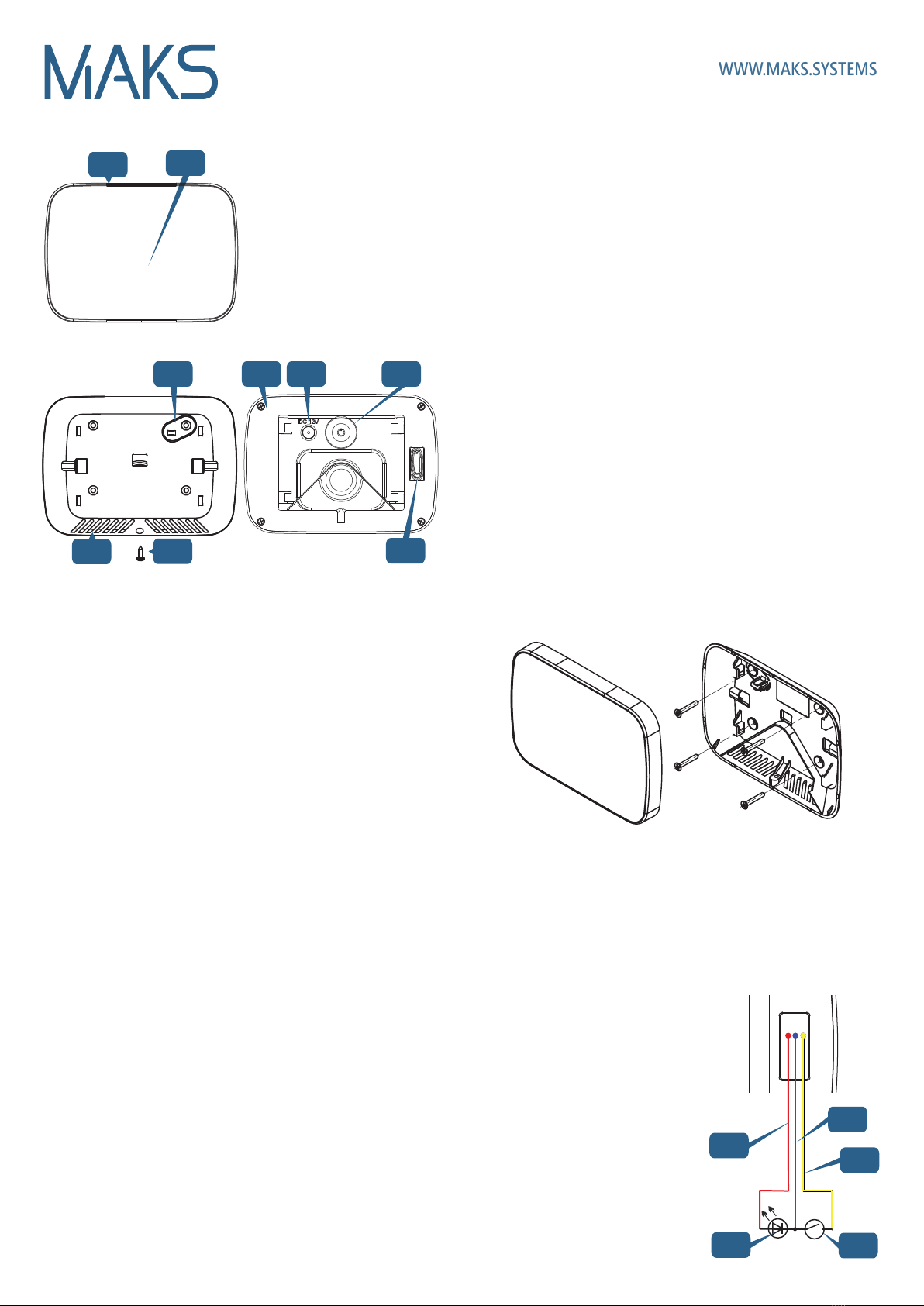
Functional parts of the device
WWW.MAKS.SYSTEMS
Selecting the installation location
Carefully select the installation location of the MAKS Siren Oudoor.
The device should not be placed:
1. In places with a high level of radio interference
2. Near objects that can cause radio signal attenuation or shielding (metal,
mirrors, etc.)
3. At a distance of less than 1 m from the security center
Installation and connection
1. Unscrew the locking screw 5
2. Move the siren upwards
3. Remove the MAKS Siren from the
backplate
4. Fit the backplate on the selected place with the screws and wall plugs
provided.
5. Place the siren on the bracket and slide it down to lock the tamper
contact. Flashes of indicator 2will confirm that the tamper is locked
in place.
6. Use the locking screw 5to fix the bottom and top parts.
Registration and setup
1. Place the siren at a distance of no more than 2 m from the MAKS
PRO security center. Registration is run at a minimal possible power to
avoid the influence of neighboring systems that can be being configured
nearby.
2. Start the MAKS SETUP application
3. Follow the application instructions to connect to the MAKS Siren
Outdoor and start the registration of MAKS wireless devices
4. Turn on the MAKS PIR, after 10-20 seconds it will be registered
5. Set up a new device in your mobile application
Switching on and off
Press button 8to switch on the device - the indicator will be on and you
will hear a sound signal.
To turn off the device, press and hold button 8for 3 seconds, until the light
indication goes out.
Before installing the MAKS Siren Outdoor, register it in the MAKS PRO
and test the siren signal level using the MAKS Setup app.
We recommend to install the device in the following order:
1. Selecting the installation location with the best signal
2. Mounting the backplate
3. Siren installation
Device installation
Battery replacement
Warning!!! Observe polarity!
1.
Unscrew the locking screw 5
and remove the device from the backplate
2.
Unscrew screws and remove
case back cover
3. Pull out and replace the batteries
4. Reassemble the device
5. Place the siren on the bracket
and slide it down until it locks
6. Use the locking screw 5to fix
the bottom and top parts.
Indication
Standby mode - indicator off
Alarm mode - light indicator flashes red, the alarm sounds
Arming confirmation - short beep. Turn on the external LED or the built-in
indicator for 15 seconds (if configured)
Armed state - flashing of the external LED or built-in indicator every 10
seconds (if configured)
Disarm confirmation - two short beeps
Connecting the reed switch
and LED
Connect the reed switch and LED
to wires as shown.
9. LD contact (+ LED), red
10. GND contact (earth), blue
11. DC contact (reed switch), yellow
12. LED (LED)
13. Reed switch
Display in communication test mode
Excellent connection - LED indicator flashes green
Normal connection - LED indicator flashes yellow
Poor connection - LED indicator flashes red
No connection - LED indicator flashes red quickly
In test mode, the unit's radio transmitter operates at medium power.
1. Siren case
2. Light indicator
3. Tamper plate
4. Resonator openings
5. Locking screw
6. Case back cover
7. Power supply connector
8. On/off button
9. Reed switch and LED connection
wires
1
5
2
3 76 8
9
4
10 12
13 14
11
Other MAKS Security System manuals


Popular Security System manuals by other brands


Smartwares
Smartwares CS96DVR Installation and operation instruction manual

Nokia
Nokia IP1220 - Security Appliance installation guide

AV-GAD
AV-GAD EasyLoader AV-706 installation instructions

Epordo
Epordo ET007V Quick manual

Radio Shack
Radio Shack CENTRAL 2000 49-351 owner's manual

Alert1
Alert1 Zoey user guide


