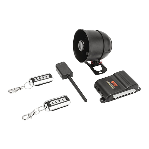
CrimeStopper SP-101 Manual

1
SP-101
REMOTECONTROLALARMSYSTEM
INSTALLATION&OPERATINGINSTRUCTIONS
INTRODUCTION
CONGRATULATIONS on yourchoiceofa“Security Plus”RemoteAlarmSystembyCrimestopperSecurity
ProductsInc.Thisbookletcontainsthe information necessaryfor installing,using,and maintaining youralarm
system.If anyquestionsarise,contactyour installationdealer orCrimestopper SecurityProductsInc.atthe
TechSupportnumber below.
This installation book is designed for the installer or individual with an existing understanding of automotive
electrical systems, alongwith theabilityto test andconnectwires forproper operation. Toease installation,
we suggestthat you READTHISMANUAL beforebeginningyourinstallation. Thisbookis provided asa
GENERAL GUIDLINE and the information contained herein may differ from your vehicle.
TECH SUPPORT
Mon-Fri 8:00 AM-4:30 PMPacificTime
www.crimestopper.com
Phone(800) 998-6880
FAX(805)581-9500
REV. A03.2010
Thisdevice complies withFCC Rules part 15. Operationissubject to
thefollowingtwo conditions: 1) Thisdevicemay not cause interference,
and(2) thisdevice must accept anyinterferencethat may be received,
includinginterferencethat maycauseundesired operation.The
manufacturer isnot responsiblefor anyradioor TV interferencecaused
by unauthorizedmodificationto thisequipment. Suchmodification
could void theuser's authority to operate the equipment.

2
TABLEOF CONTENTS
InstallationCautions&Warnings…….………………………………………………………….……….…….……2
ControlModule&ComponentMounting…………….………………………..…………………..….….…….…..3
Wiring……..……………………………………………………………………………………………………...…….4-5
PowerDoorLockWiring...…………………………………………………….………..………………….…………6
TransmitterProgramming…………………………………………………………………………………….………7
OptionProgramming………………………………………….………………………………..………………….8-10
OperatingInstructions………………………..……………………………………………………..……..…….11-13
CarJack Protection…………………………………………………………….…………..…….……..……………14
LED/ ValetSwitch……………………………………………………………………….………………..…..………15
Shock Sensor……...…………………………………………………………………………..…………..…..………15
SystemWiringDiagram……………………………………………………………………………………...………16
INSTALLATIONCAUTIONS&WARNINGS
BEFOREBEGINNING,checkall vehiclemanufacturercautionsandwarningsregardingelectricalservice(AIR
BAGS, ABS BRAKES, ENGINECOMPUTERS, BATTERYetc.).
WE RECOMMEND theuseofaVOLT/OHMMETERtotest and verifywiringcircuits. Testlightsorilluminated
probescancausedamagetoon-boardcomputer or enginemanagementsystems.
DONOTexceedmaximumoutputratings or damagemayoccur.Electricalcurrentlimitsfor thisalarmare
listed where applicableon the systemdiagram(Pg.16).Ifyouareunsureaboutthe currentload,of aspecific
circuitonyour vehicle, measure theloadfirstwithanamp-meterbeforeconnecting.
WE RECOMMEND that theMAINSYSTEMFUSE beREMOVED before jumpstarting,using abattery
charger,or changing the battery. Avoltagesurgeorhigh boost conditioncoulddamage alarmcircuits.
DONOTROUTEANYWIRINGTHATMAYBECOMEENTANGLED withbrake,andgaspedals,steering
column,or anyothermovingpartsinthevehicle.

3
CONTROL MODULEMOUNTING
DO NOTMountthecontrolunitintheenginecompartment!
DONOTMountthecontrolunitorwiring harnesswherethey canbecomeentangledwithmovingparts
suchas brake/gas/clutchpedals,orthesteering column!
Thealarmcontrolmoduleshouldbe mounted inaconcealed location.ThePlacementofthe modulewill
affectthedistancefromwhichtheremotetransmittercancontroltheunit. Theantenna wire shouldberouted
awayfromanymetalifpossible.Donotalterthelengthoftheantennawireor routeitwithotherwires.Do
notgroundthe antenna wire. Fasten themoduletoabracketor wire harness usingthecabletiesprovided.
UnderdashMounting: Ifyouare locating the controlunitunderdash,mountitashigh aspossible,noteasily
located byan intruder.
Driver’sSideUnderdash mountingprovidesan easylocationforwiring mostofthesystem’sconnections,
however thisisacommon location foran intruder tocheckfor an alarmafterbreaking intothe vehicle.The
left sideofthe vehiclemaycontainmore metaland orwiringthatwill createinterferenceand decreasethe
operating rangeofthesystem.
PassengerSideunderdash isagoodlocation,however someextrawiring maybe neededtoextendwires
across fromthedriver’sside.
Under-seat/CenterConsole mounting isalsoapossibility,butNOTRECOMMENDED.Thesystem’s
transmitterrangewill bereducedbythemetalstructuresofthe seatorcenterconsoleand the unitmayalso
be exposedtomoisturefromspilled drinksetc.Moisture orwater damageisnotcoveredunderthewarranty
andwill besubject torepaircharges. Underseator consolemountingwillcreatemoredifficultyifyou needto
accesstheunit forserviceorwant toadd-on featuresor connectionslater. Usethislocationasalastresort.
COMPONENT MOUNTING
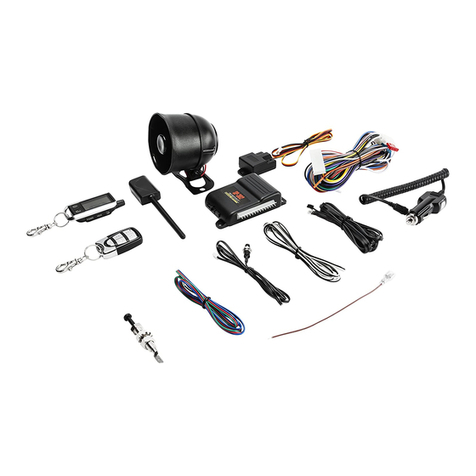
SIREN: Mountthesiren underthehoodtoan innerfender-well or other bodysurfacewiththe openend facing
downward.
SHOCK SENSOR: Mounttheincludedshocksensor withwire tiestoan under dashwire harness or fasten
withscrewstofirewall or side paneling.Usetheadjustment screwtosetthesensitivityofthesensor.
LED: MounttheLEDstatusindicatorinavisiblelocation on thedashboardorconsole.
VALETOVERRIDEPROGRAMBUTTON: Mountthe Valet/Override/Programpush-buttoninahidden but
accessiblelocation. It isREQUIREDforemergencydisarm, programming, andValetMode.

4
WIRING
GREENWIRE:(-)DOORTRIGGER
Identifythe wire thatreadsgroundwhen anydoorisopen and12voltswhen all doorsare closed.Some
vehiclesmayhaveisolateddoortriggers.Inthiscaseyoumayneed torun additionalwiresfromother doors
or godirectlytothe wirethattriggersthe vehicle’sinteriordome light.Onevehiclewill notrequiretheuseof
BOTHdoor triggerwires.
PURPLEWIRE:(+)DOORTRIGGER
SameastheGREENwire aboveexcept thiswireisusedforvehiclesthat showapositivevoltage (12volts)
whenthedoorisopenandagroundwhendoorsareclosedasinmanyFord,Lincoln,andMercuryvehicles.
YELLOWWIRE:IGNITIONSWITCHED“ON”AND “START”12VOLTS
ConnecttoanIGNITIONwire(orfuseinthefusebox)thatshows12Voltswhenthe keyinboth “ON” and
“START” positions.
BLACK WIRE:SYSTEMCHASSISGROUND
The Blackwire MUSTbe connected the CHASSISMETALofthevehicle.Scrapeawayanypaintordebris
fromtheconnection pointanduseastarwashertoensure agoodconnection.Keepthegroundwireshort.
GRAYWIRE:(-)AUXREMOTEOUTPUT1(Optional, may requirearelay)
Connecttothe Negativetrunkreleasecircuit ortotheactivationcircuit of anauxiliarymoduleordevice.If the
circuitrequires12V,thenarelayisrequired.RELAYWIRING:Connectthe Graywire toterminal85,connect
relayterminals86 and 87to12Vconstantpower.Connectterminal30 ofthe relaytothe 12Vpositive
device/circuittobe activated.
BLUEWIRE:(-) HOOD/TRUNK TRIGGER
Inputtriggerforagroundinghoodortrunkpinswitch.Connecttoexistinghoodandtrunkpinswitchesthat
readground when open.Ifnoexistingswitchesare available,install newpinswitchesifdesired.Note:DO
NOTmountnewpinswitchesinwater pathways.
BROWNWHITEWIRE:(-) HORN PULSE OUTPUT(Optional, mayrequirearelay)
Connect totheNegativeHornTriggerwire usuallylocated near thesteeringcolumn.Ifthevehiclehorncircuit
requires12V,thenarelayisrequired.RELAYWIRING:Connectthe Brown/Whitewire toterminal85,
connect relayterminals86and 87to12Vconstant power.Connect terminal30of therelaytothe12Vpositive
device/circuittobe activated.

5
WIRING
ORANGEWIRE:(-)NEGATIVE ARMEDOUTPUT/STARTERDISABLE(500mAGround,Optional)
Thiswirebecomesa(-) GroundOutputwhentheSystemisArmed.Thisoutputisused for disabling the
starter ortoactivateoptionaldevicessuchasextrasensors,LED’s,windowroll-upmodules,voicemodules
etc.ForStarterKill,cutstarterwire and connectbetween 87Aand 30 onrelay.Connectorangewire to85
and connect86toan Ignition sourcethathasvoltage inthe ONand CRANKINGposition.(Seewiring
diagramfor relayconfigurationpage16)
BROWNWIRE:(+)SIRENOUTPUT(3AmpMax.)
ConnecttoREDsiren wire fromtheSiren intheengine compartment.
WHITEWIRE:Two12VFLASHINGLIGHT OUTPUTS(7.5Ampx2)
Connecttotheswitched parking lightwire atbackoflightswitch.If thisisnotpossible,connectdirectlytoone
oftheparking lightsatthe frontofthe vehicle.Somevehiclesrequire separaterightand left circuits.Usethe
oneWhitewirefor eachcircuit(Useseparate7.5Ampfusefor eachcircuit).
REDWIRE:12VPOWERINPUT(15ampfuse)
Connectto12 Volt sourcewithsuppliedfuse&holder. Recommendedlocationforthisconnection isatthe
vehiclebatterypositiveterminal.
2PINPLUG(WHITE):VALETPROGRAMandOVERRIDEPUSH-BUTTON
2PINPLUG(RED):ALARMSTATUSLEDINDICATOR
4PINSENSORPLUG (RED):
GREENWire: NegativeTrigger.
WHITEWire: NegativeWarn-A-Way.
BLACK Wire: Sensor Ground.
RED Wire: Sensor 12VPower.
SHOCK SENSOR: The sensorsupplied with
thissystemdoesnotrequire anyadditional
wiring.Simplymountthesensorinasuitable
location,plugit in,andadjustthesensitivity.
SENSORADJUSTMENT
Clockwise =HigherSensitivity
CounterClockwise =LowerSensitivity

6
POWERDOORLOCK WIRING
GREENWHITE: (-)NegativeLOCKPulse, BLUEWHITE: (-) NegativeUNLOCKPulse
NEGATIVETRIGGERDOORLOCK WIRING POSITIVETRIGGERDOORLOCK WIRING
GREENWHITE
GREENWHITE FUSED
+12V
BLUEWHITE +
BLUEWHITE 86
858685 8787 3087A30
87A
FACTORY
FACTORY
LLPOWER
POWER LOCKING
LOCKING
UL UL
RELAYS RELAYS
ADDINGAFTERMARKETDOORLOCK MOTORSREVERSEPOLARITYDOORLOCK WIRING
GREENWHITE
GREENWHITE FUSED
FUSED +12V
+12V
BLUEWHITE
BLUEWHITE +
+
86858685
86858685 8787
8787 3087A3087A
3087A3087A
+LCUT
UL CUT
MASTER
SWITCH

7
REMOTETRANSMITTERPROGRAMMING
1.Turn Ignition ON.
2. Press the Program/Override Button4times.After afewsecond delay,the unitwill chirpandflashthe
lights4times.
3.Press button1ontheremotecontrolyou wishtolearn.Youshouldget2lightflashesindicating theunit
iswaiting for a2nd code,then pressbutton#1 ofasecondtransmitter ortransceiver,the unitwill chirp
andflashthelights3timesindicatingitswaiting forthe3rd codeand4times.Ifall 3codesarelearned,
the unit will automaticallyexit code-learning mode, otherwiseturn keyoff toexit programming mode.
Note1:All transmittercodesmustbelearnedatthetimeofprogramming.Anytransmittersnotpresentwill
be dropped fromsystemmemory. Thissystemwill learn atotalof3transmittersmax.
IGN
OFF
WAIT FOR
4FLASHES
PRESSPROGRAM
FLASH2, 3, or4X's
IGN
OFF
PRESS LOCKBUTTON
TURN IGNON
4TIMES
ONEACH REMOTE

8
OPTIONPROGRAMMING
1. TurntheIgnitionON and press the Override/Program button5times. After aslightdelay, thesystem willchirp and
flashthe lights 5 times.
2. Withinthenextfew seconds, press the Override/Program button[again]thenumber of times thatcorresponds to
the feature list below. The sirenandhornwillchirp for eachbuttonpress. DO NOT LOSE COUNT!!
3. Whenyouget to thedesired optionnumber, quicklypress theappropriate buttonontheremote control accordingto
thechart below. Button1gives asinglelightflash/chirp, Button2gives two lightflashes /chirps, andButton3
gives three light flashes / chirps.
4. TurnIgnitionOff. System chirps andflashes thelights 3times onexit. Whenyouarefinished customizingoptions,
checkoperation.
PROGRAMMINGOPTIONS CHART *=DefaultSettings
Option#
OPTIONDESCRIPTION BUTTON1
LOCK BUTTON2
UNLOCKBUTTON3
SILENTX
1. FactoryHorn ChirpsPulses Pulsewithtrip
only ArmDisarmChirps
&Pulsewithtrip *ArmDisarmWarn Chirp
&Pulsewithtrip
2. PassiveArming / ON *OFF*
3. Ignition Controlled Locks *ON* OFF LockOnly(nounlock)
4. 5/60Second
DoorOpenWarning 5Sec. *60 Sec.*
5. ActiveRe-Arm *Enabled* Disable
6. DoubleUnlockPulse *Disabled* Enable
7. Disarmwithtrunkpop Disable *Enabled*
8. DoorLockPulseTime *0.75 Sec.* 3Sec.
9. Typeof CarjackProtection *Active* Active&Passive Full-Time
10. CarjackFeature *Disabled* Enable
11. Parking Lightsonwithdisarm *Enabled* Disable
12. PassiveLock ON *OFF*

9
OPTIONPROGRAMMING
NOTE:OptionscanbeinstantlyrestoredtoFactoryDefaultValues.
To restoredefaultvalues:
Perform step#1above, thenpress button3. Thesirenand hornwill chirp4timesandlightswill flash
4times.TurnOFFIgnition. All programmingoptionswill berestoredto*Default*values,
See Programming Chart.
1. HORNCHIRPS PULSES
Thisoptioncontrolsthesystem’sHorn-honkoutput.Thereare3selections:Button1(Lock)=HornPulseonly
whenalarmistripped.Button 2(Unlock)=HornChirpsfor Arm/DisarmandPulsewhentripped.Button3
(Silent X)=HornChirpsforArm, Disarm, andPre-warning protection.Thehorn outputpulseswhentriggered.
2. PASSIVE ARMING
ThisoptioncontrolsthePassive(Automatic)Arming feature.IfON,armingwill occur 40Secondsafter the
ignitionisturned offandthelastdoorhasbeen closed.The LEDwill beginflashing rapidlywhilecounting
down.If adoorisreopened,the systemwill waitfor thedooror zonetoclosebeforearming.The unitwill
flashthelightsonce.Doorswilllockifpassivelocking isselected.FactorydefaultsettingisON. Note:Ifyou
Disarm Systemand Re-Enterthevehicle,youmustturnIgnitionKeyONandOFFforPassive Arming
toreactivate.
3. IGNITIONCONTROLLEDLOCKS
Thisoptioncontrolswhether the locks are controlledbyIgnition.There are 3selections:Button 1(Lock)=
Lock/UnlockwithvehicleIgnition. Button 2(Unlock)=NoIgnition locks. Button3=IgnitionLockonly.
4. 5/60Sec. DOOROPENWARNING
Thissettingchangesthedelaytime inwhichthealarmsystembeginstomonitor theDoorcircuit.Thisoption
can prevent the alarmfromgivingwarning chirpsonvehicleswithadelayeddomelight.
5.ACTIVE RE-ARMING
ActiveRe-arming allowsthe systemtore-armitself40 secondsafter disarmed withthetransmitter ifadoor
hasnotbeen opened.Thisishandyifthe vehicleisaccidentallydisarmed(viatheTransmitterinyourpocket)
withoutyouknowing it.

10
OPTIONPROGRAMMINGCont.
6. DOUBLEUNLOCK PULSE
The unitwill send2UnlockPulseswhenthe#2Unlockbuttonispressed. Thisfeature mayberequiredfor
interfacing thisalarmwithan existing FactoryKeyless EntryorAlarmsysteminavehicle. Thesesystemsare
found on someNissan, VW, Toyota, andLexusvehicles.
7. DISARMWITHTRUNKPOP
Controlswhetherthe AlarmSystemwillDisarmwhentheTrunkPop featureisused. When theOption7is
turnedon, the AlarmDisarmswhen Poppingtrunkorusing anAUXdevicecontrolled bytheGrayoutput wire.
8. DOORLOCK/UNLOCK PULSE TIME
Controlstheamountof time (0.75sec.or 3sec.)fortheLockandUnlockPulse. The3sec.settingmaybe
required for 1980’/90’sEuropeanVehiclesthatrequirealongpulsetodoVacuumdoor locksystems.
9.ACTIVE, PASSIVE,orFULLTIMECARJACK PROTECTION
Thisfeature controlsthetypeof Carjack protectionthealarmwill provide. There are3selections: Button1
(Lock)=Activeprotection. Button2(Unlock)=ActiveandPassiveprotection. Button3=Full-Time
protection.Optionnumber10mustbeenabledtoallowCarjackfunctionstooperate.
10. CARJACKFEATURES
Thisoptioncontrolsthe unit’sCarJackfeatures. Enableor DisableCarjack(TurnONor OFF)withthisoption.
11. PARKINGLIGHTSONWITHDISARM
KeepsParking lightsON30 secondsinsteadof2flasheswhen systemisdisarmed.Thisisfor added security
andtoassistinlocatingyour vehicleinacrowded parking lot orstructure.Lightwill stayonfor 30 Sec.or until
Ignition isturned on.
12. PASSIVE LOCKS
Thisoptioncontrolswhetherthedoorswill lockwhenPassiveArming occurs.Note: Thisfeaturemay
increasetheriskoflockingkeys inthevehicle.

11
OPERATINGINSTRUCTIONS
ACTIVE ARMING
Toarmthe alarmand lockthe doors,press the#1 Button (Lock
Symbol)onthetransmitter.Youwill hear asinglesiren chirpandthe
lightswill flashonce.The systemwill arm,thedoorswill lockand the
starterwill be disablediftheseoptionalfeaturesareinstalled.Aftera
short5second delaytoallowvehicleandelectronics tosettle,the
systemwill becompletelyarmed.ThealarmstatusLEDinthe vehicle
will beginflashing.
SILENTARMING
Tosilentlyarmthealarmandlockthe doors,press the #3Button
(XSymbol)onthetransmitter. Onlythelightswill flashonce.
PASSIVE ARMING
If programmed,Passive(Automatic)Arming will occur40Secondsafter
the IgnitionisTurnedOffandthelastdoorhasbeenclosed.TheLED
will beginflashing rapidlywhilecounting down.Ifadoor isreopened,
thesystemwill waitforthedoor orzone toclosebeforearming.The
unitwill flashthelightsonce.Doorswill lockifthe “PassiveLocking”
featureisON.PassiveArm/Lockmayqualifyforinsurancediscounts,
checkwithyour agentor proprietor
DISARMING
ToDisarmthe Alarmand Unlockthe doors,press the#2 Button (UnlockSymbol)onthe transmitter.You will
hear2sirenchirpsandthelightswillflashtwice.LEDstopsflashing. Doorswillunlockanddomelight will turn
on iftheseoptionalfeaturesare installed.
SILENTDISARMING
Tosilentlydisarmthe alarmandunlock the doors,press the #3 Button (XSymbol),thenpress the #2 (Unlock
Symbol)on the transmitter.Onlythelightswill flashtwice.
TRANSMITTERBATTERYREPLACEMMITTER=GP27A(Mini12 voltBattery)
4
BUTTONREMOTE
TRANSMITTER

12
OPERATINGINSTRUCTIONSCont.
ACTIVE RE-ARMING(FAILSAFEPROTECTION)
The ActiveRe-Armingfeature allowsthe systemwill Re-Armitself40secondsafter beingdisarmedwiththe
transmitter ifadoor hasnotyetbeenopened.Thisishandyifthevehicleisaccidentallydisarmed(viathe
transmitter inyourpocket)withoutyouknowing it. Thisfeature canalsobe turned ONor OFF inprogramming
(option#5).
ALARMTRIGGERING
Ifthereisan intrusion intothe vehicleor hard impacttothe bodywill soundthe alarmand flashthelightsfor
45 seconds.After45secondsthesirenandlightswill stop,butthe alarmisstill armedtocontinue toprotect
the vehicle.Ifanintruder left the door open,theunitwill cycleasecondtimebefore stoppingand then
continuetoprotect the other un-tampered zonesof thevehicle.
ALARMTRIGGERRESET
If thearmedalarmsystemistriggeredwhileyou arewithintherange oftheremote,pressingButton#1,2or3
will onlyshutoff the siren andlightswhileleaving the alarmstill inan armedstate.ToDisarmtheAlarmwhen
it isinatriggered state,youmust press the #2Button twice.
CARFINDERMODE
When the alarmsystemisarmed,pressButton#1 (LockSymbol).Thesiren will chirp onceandthe lightswill
continuetoflash10times.
SILENTCARFINDERMODE
When the alarmsystemisarmed, pressButton #3 (SilentXSymbol). Theparking lightswill flash10 times.
REMOTEPANICPROTECTION
Tosound the alarmuponcommand (panic),press and holdButton#1 foratleast3secondsuntil thesiren
sounds.Press Button#1againtoresetpanicmode.
TRUNK HATCHPOP(OPTIONAL)
ToPoptheTrunk(ifoptionalfeatureisinstalled),pressButton#4(TrunkSymbol)onthetransmitterforat
least1second.If thesystemisarmed, pressing Button4mayormaynottripthe alarmsystemwhen opening
the trunkdependingonprogrammingoption#7. See page8.

13
OPERATINGINSTRUCTIONS
EMERGENCYOVERRIDE&DISARM
Ifyou havelostthetransmitter or itstopsworking for anyreason andtheAlarmisarmed,youwill haveto
performand EmergencyOverride toDisarmthe Alarm.Open thedoor withthekey,(alarmwill sound).Turn
the ignition on andpresstheoverride/programbutton 4-5seconds(until siren stops). The Alarmwill disarm.
VALETMODE(SolidLEDonDash)
Todisablethe Alarmsystemforvehicleserviceor otherwise,turntheignitiononandpressthe
override/programbutton4-5secondsuntil thedashLEDturnsonsolidandyou hear(1) sirenchirp.Repeat
the processtoexit VALETmodeandthesystemwill chirp(2)timesandthe LEDwill turnoff. LockUnlockand
AUXfeatureswill still operateinwheninVALETmode.
PRIORINTRUSIONALERT
Ifthesystemwastrippedinyourabsence,thedashLEDwillbeflashing rapidly.When thesystemis
disarmedyouwillhear 4chirpsand flashes.Carefullyinspectyourvehicle.
OPENZONEALERT&BYPASS
Ifthesystemdetectsafaultyoropenzone(Doorleftopen)whenthesystemisACTIVELYARMED,thesiren
andhorn will chirp 3timesalong with3light flashes.The faultyzonewill beautomaticallybypassed.
IGNITION-CONTROLLEDDOORLOCKS
Ifthisfeature isenabled,the doorswillautomaticallylockwhenthe ignitionisturnedonandwill unlockwhen
the ignition isturned off. Thisfeaturecan be programmed ON, OFF(option #3).
PRE-WARNINGSHOCK PROTECTION&SENSORADJUSTMENT
Ifalow-levelshocktothevehicleisdetected,pre-warningprotectionwillactivatesounding5quicksiren chirps
and1lightflash.If ahard impactisdetected the shocksensor shouldtripthealarmsystem.Onceitis
mounted,adjustthesensor asneededbyturning theadjustmentscrewclockwisetoincreaseorcounter-
clockwisetodecreasethesensitivity.The sensorisalsoequippedwith2small indicatorlightstoeasethe
adjustmentprocess. Greenlight =Pre-warning disturbance(5 sirenchirps). Red light =Afull alarmtrigger.

14
CARJACKPROTECTION
ACTIVE CARJACK
Thisfeature providesActiveCarjackprotection and mustbeenabled before usethrough Alarmprogramming
(option 10).Seepage8.When theIgnition ison (running),press button#2(UnlockSymbol).Parking lights
will flashTWICEtoconfirmtheCarjackcountdownsequence.90 Secondslater,theunitwill beginaCarjack
Cycleconsisting of20 secondsofpre-warningchirpsturning intoafull systemactivation withsiren/flashing
lightpulsesfor 5min. ToresetActiveCarjack, IGNITIONMUSTBE ON, thenpress Button#2again.
PASSIVE CARJACK
ThisfeatureprovidesPassiveCarjackprotectionandmustbe enabled beforeusethroughAlarmprogramming
(options9and 10).Seepage8.Werecommendthismode shouldonlybe used inserioussituations.When
the Ignition ison (vehicleisrunning),and adoor isopened,the Carjackcountdownsequencewill be initiated.
90 Secondslater,the unitwill beginaCarjackCycleconsistingof20 secondsofpre-warning chirpsturning
intoafull systemactivation withsiren/flashing lightpulsesfor5min.ToresetPassiveCarjack,IGNITION
MUSTBE ONAND DOORSMUSTBECLOSED,then press the override/programbutton(3) times.
FULL-TIMECARJACK
UseincaseofextremeCarjackthreatonly.Thisfeatureprovidesfull-timeCarjackprotectionandmustbe
enabledbeforeusethroughAlarmprogramming options(9) &(10).See page8.EVERYTIMEthe Ignition is
turnedONoradoor isopened,thenclosedwiththe IgnitionON,aCarjackcountdownsequencewill be
initiated.90 Secondslater,theunitwillbeginaCarjackCycleconsistingof20secondsofpre-warningchirps
turning intoafull systemactivation withsiren/flashinglightpulsesfor5min.You mustresetthe unitevery
timetheIGNITIONisturnedonor adoor isopened andclosedwhen the ignition ison.
To RESET:IGNITIONMUSTBEONAND DOORSMUSTBECLOSED,thenpressoverride/programbutton
(3) times.
NOTE:WhenFULLTIMECARJACK isineffect, itmust bereset everytimethekeyisturnedon, Door
isopened,beforeentering VALETmode,andbeforeProgrammingoptionsortransmitters.Itisalways
ineffecteachtimetheIgnitionisturnedon and/oradoorisopenedwithIgnitionon.

15
LED/ VALET SWITCH MOUNTING
LED: The LEDisused asaSystemStatusIndicatoranditwill alsoFLASHforuseassecuritydeterrentwhen
the AlarmSystemisArmed.
VALETSWITCH: MounttheValetSwitch(push-button) ondashor otheraccessiblelocation.It isREQUIRED
for EmergencyDisarm, Programming and enteringValetMode (Seepg13forValetMode).
VALET/PROGRAMSWITCH
STATUSLED
WIRING:SHOCK SENSOR
4PINSENSORPLUG/HARNESS (RED):
GREENWire: NegativeTrigger.
WHITEWire: NegativeWarn-A-Way.
BLACK Wire: Sensor Ground.
RED Wire: Sensor 12VPower.
SHOCK SENSOR: The sensorsupplied with
thissystemdoesnotrequire anyadditional
wiring.Simplymountthesensorinasuitable
location,plugit in,andadjustthesensitivity.
SENSORADJUSTMENT
Clockwise =HigherSensitivity
CounterClockwise =LowerSensitivity

16
WIRINGDIAGRAMSP-100
Purple
Green/white
Blue
Brown/white
Red
Black
Blue/white
Yellow
Orange
Green
Brown
Gray
White
Ground
12 Volt
Battery
Hood Switch
DoorSwitch
(-)
86
85 87
30
87A
(-)
IgnitionSense
(+)
(-)
(-)
Starter
Kill Relay
(-)
(-) Arm
HornHonk FactoryCarHorn
(+)ParkingLights
TrunkPopRelay
RemoteOutput
(+)Siren
86
85
87
30
87A
15 AMP
FUSE
White
STARTER
CUT
SOLENOID
IGNITION
"ON and START"
(-)
Lock
Unlock
DOORLOCKS
DoorSwitch
(+)
86
85 87
30 87A
(+)ParkingLights
7.5AMP
FUSE
7.5AMP
FUSE
(500mA)
(500mA)
(500mA)
(+)

changes or modifications not expressly approved by the party responsible for compliance
could void the user's authority to operate the equipment.
NOTE: This equipment has been tested and found to comply with the limits for a
Class B digital device, pursuant to Part 15 of the FCC Rules. These limits are
designed to provide reasonable protection against harmful interference in a
residential installation. This equipment generates, uses and can radiate radio
frequency energy and, if not installed and used in accordance with the
instructions, may cause harmful interference to radio communications. However,
there is no guarantee that interference will not occur in a particular installation.
If this equipment does cause harmful interference to radio or television reception,
which can be determined by turning the equipment off and on, the user is
encouraged to try to correct the interference by one or more of the following
measures:
-- Reorient or relocate the receiving antenna.
-- Increase the separation between the equipment and receiver.
-- Connect the equipment into an outlet on a circuit different
from that to which the receiver is connected.
-- Consult the dealer or an experienced radio/TV technician for
help.
FCC ID: CHXSP101
This device complies with Part 15 of the FCC Rules. Operation
is subject to the following two conditions: (1) this device may
not cause harmful interference, and (2) this device must accept
any interference received, including interference that may cause
undesired operation.
Table of contents
Other CrimeStopper Security System manuals

CrimeStopper
CrimeStopper Cp-4900 User manual

CrimeStopper
CrimeStopper SP-102 User manual

CrimeStopper
CrimeStopper CS-2002DC.IV Manual

CrimeStopper
CrimeStopper CG-1000 User manual

CrimeStopper
CrimeStopper SP-302 User manual

CrimeStopper
CrimeStopper CS-872 User manual

CrimeStopper
CrimeStopper CS-2000DPII SERIES IV Manual

CrimeStopper
CrimeStopper SP-102 User manual

CrimeStopper
CrimeStopper CS-2004DC II User manual

CrimeStopper
CrimeStopper RS901 RS900ER User manual