MAKSIWA BMS.3200.IR User manual
1
BMS 3200.IR
INSTRUCTION MANUAL
Sliding Panel Saw 3200 mm
ATTENTION: FOR YOUR SAFETY, READ INSTRUCTIONS CAREFULLY BEFORE ASSEMBLING
OR USING THIS PRODUCT. SAVE THIS MANUAL FOR FUTURE REFERENCE.

2
Greetings,
Congratulations, you just purchased the BMS.3200.IR Precision Saw, which was
developed with the Maksiwa’s highest standards of technology and quality.
Your BMS.3200.IR Precision Saw allows you to have the highest productivity in
woodworking. Besides a great fi nish, the BMS.3200.IR ensures that your cuts are
always precise. It should be noted that to use this machine with maximum effi ciency,
you should read and understand the instructions in this manual.
Visit our website to know about other products and technical assitance:
www.maksiwa.com/usa

3
Attention!: The machine must be inspected immediately upon arrival. If the machine has been
damaged during transport, or if any parts are missing, a written record of the problems must be
submitted to the forwarding agent and a damage report compiled. Also be sure to notify your
supplier immediately.
For the safety of all personnel, it is necessary to study this manual thoroughly before assembly
and operation. This manual must be kept in good condition and should be considered as part
of the machine. Furthermore, the manual must be kept to hand and within the vicinity of the
machine so that it is accessible to operators when using, maintaining or repairing the machine.
!
Maksiwa International Inc.
4100 N Powerline Rd, Suite D3 Pompa-
no Beach, FL
Call us free: 844-319-6594
www.maksiwa.com/usa

4
Contents
1.General.....................................................................................................................................................................05
1.1 Foreword.........................................................................................................................................................05
1.2 Machine Identifi cation ..................................................................................................................................05
1.3 Customer Service recommendations ........................................................................................................05
1.4 Copyright .....................................................................................................................................................06
1.5 Spare Parts .....................................................................................................................................................06
1.6 Disposal .........................................................................................................................................................06
2. Safety Precautions...............................................................................................................................................07
2.1SafetyRegulations...........................................................................................................................................07
2.2 Residual Risks ................................................................................................................................................08
2.3 Safety and Information Signals.....................................................................................................................09
3. Specifi cations......................................................................................................................................................10
3.1 Main Components ..........................................................................................................................................10
3.2 Technical Specifi cation .................................................................................................................................10
3.3 Electrical Connection ...................................................................................................................................11
3.5 Noise Level ....................................................................................................................................................13
3.5 Dust Extraction .............................................................................................................................................13
3.6 Safety Devices...............................................................................................................................................14
4. Installation............................................................................................................................................................15
4.1Contents of Package .....................................................................................................................................15
4.2 Lifting and Unloading ....................................................................................................................................17
4.3 Installation Zone Characteristic .................................................................................................................17
4.4 Install of Loose Parts - Introduction ................................................................................................................18
5. Adjustment ..........................................................................................................................................................21
5.1 Setup and Control ............................................................................................................................................... 21
5.2 Extension Table Flatness Adjustment .............................................................................................................21
5.3 Rip Fence Precision Adjustment ....................................................................................................................22
6. Operating Procedures ........................................................................................................................................26
6.1 Machine Start And Stop ...............................................................................................................................26
6.2 Working Station ............................................................................................................................................26
6.3 Working with the Machine ...........................................................................................................................27
6.4 Correct Use for this Machine .........................................................................................................................28
7. Maintenance ........................................................................................................................................................29
7.1 Repace Saw Blade .........................................................................................................................................29
7.2 Overall Cleaning ............................................................................................................................................29
7.3 General Lubrication .......................................................................................................................................30
7.4 Replacement and Disposal .........................................................................................................................30
8. Trouble Shooting .................................................................................................................................................31
9. Exploded View .....................................................................................................................................................32
10. Terms of Warranty ..............................................................................................................................................56

5
1 General Information
1.1 Foreword
This machine is desinged to make straight and angle cut for wood material, especially for wood board cutting.
Some information and illustrations in this manual may difer from the machine in your possession, since all the
confi gurations inherent in the machine complete with all the optionals are described and illustrated. Therefore,
refer only to that information strictly connected with the machine confi guration you have purchased.
With this manual we would like to provide the necessary information for maintenance and proper use of
the machine. The distribution network is at your service for any technical problem, spare parts or any new
requirement you may have for the development of your activity.
This manual must be read and understood before operating the machine. This will provde a better working
knowledge of the machine, for increased safety and to obtain the best results.
To facilitate its reading, the manual has been divided into sections pointing out the most important operations.
For a quick research of the topics, it is recommended to consult the index. To better stress the importance of
some basic passages, they have been marked by some preceding symbols:
WARNING
Indicates imminent risks which may cause serious injury to the operator or other persons.
Be careful and scrupulously follow the instructions.
CAUTION
A statement advising of the need to take care lest serious consequences result in harm to material
items such as the asset or the product.
1.2 Machine Identifi cation
There is a identifi cation plate fi xed to the machine, containing the manufacturer’s data, year of construction,
serial number and technical specifi cations.
1.3 Customer Service Recommendation
Apply the machine to skilled and authorized technical staff to carry out any operation dealing with parts
disassembly. Keep to the instructions contained in this manual for the correct use of the machine.
CAUTION
Only skilled and authorized staff shall use and service the machine after reading this manual.
Respect the accident prevention regulations and the general safety and industrial medicine rules.
1 General
Indicates imminent risks which may cause serious injury to the operator or other persons.

6
1.4 Copyright
This manual should be handled confi dentially. It is designated solely for those persons who work on or with the
machine. All descriptions, texts, drawings, photos and other depictions are protected by copyright and other
commercial laws. Illegal use of the materials is punishable by law.
This manual, in its entirety or parts thereof, may not be transferred to third parties or copied in any way or
form, and its contents may not be used or otherwise communicated without the express written consent of
the manufacturer.
Infringement of these rights may lead to a demand for compensation or other applicable claims. We reserve
all rights in exercising commercial protection laws.
1.5 Spare parts
Attention: Non genuine, counterfeit or faulty spare parts may result in damage, cause malfunction or
complete breakdown of the machine.
If unauthorized spare parts are fi tted into the machine, all warranty, service, compensation and liability claims
against the manufacturer and their contractors, dealers and representatives shall be rejected. Use only genuine
spare parts supplied by the manufacturer. Unless, specifi ed by manufactor.
1.6 Disposal
Attention!: Used electrical materials, electronic components, lubricants and other auxiliary substances
must be treated as hazardous waste and may only be disposed of by specialised, licensed fi rms.
If the machine is to be disposed of, separate the components into the various materials groups in order to
allow them to be reused or selectively disposed of. The whole
structure is made of steel and can therefore be dismantled without problem. This material is also easy to
dispose of and does not pollute the environment or jeopardize public health. International environmental
regulations and local disposal laws must always be complied with.
1 General
!

7
2 Safety Precautions
2.1 Safety Regulations
WARNING
Indicates imminent risks which may cause serious injury to the operator or other persons.
Be careful and scrupulously follow the instructions.
The manufacturer disclaims all responsibilities for damages to persons or things, which might be caused by
any failure to comply with the safety regulations.
• The machine operator shall have all necessary prerequisites in oder to operate a complex machiery.
• It is prohibited to use the machine when under the infl uence of alcohol, drugs or medication.
• All the operators must be suitably trained for use, adjustment and operation of the machine.
• The operators must carefully read the manual paying particular attention to the warning and safety
notes. Furthermore, they must be informed on the dangers associated with use of the machine and the
precautions to be taken, and must be instructed to periodically inspect the guards and safety devices.
• Before carrying out adjustment, repair or cleaning work, disconnect the machine from the electric power
and lock the disconnect switch in its “OFF” position by setting the main switch to stop.
• After an initial bedding-in period or many hours of operation, the driving belts may slacken; this causes an
increase in the tool stopping time (the stopping time must be less than 10 seconds). Immediately tighten
them.
• The working area around the machine must be kept always clean and clear, in order to have an immediate
and easy access to the switchboard.
• Never insert materials which are different from those which are prescribed for the machine utilization. The
material to be machined must not contain any metal parts.
• Never machine pieces which may be too small or too wide ithrespect to the machine capacity. - Do not
work wood which has evident defects (cracks, knots, metal parts, etc.)
• Never place hands among the moving parts and/or materials.
• Keep hands clear from the tool; feed the piece with the aid of a pusher.
• Keep the tools tidy and far away from those not authorized persons.
• Never employ cracked nor uckled, neither not correctlyreground tools.
• Never use the tools beyond the speed limit recommended bythe producers.
• Carefully clean the rest surfaces of tools and make surethat they fi nd perfectly horizontally positioned, and
with no dents at all.
• Always wear gauntlets when handling the tools.
• Mount the tools in the right machining direction.
• Never start the machine before having correctly installed all the protections.
2 Safety Regulations
Indicates imminent risks which may cause serious injury to the operator or other persons.

8
• Connect the dust suction hoods to an adequate suction system; suction must always be activated when
the machine is switched on.
• Never open doors or protections when the machine or the system is operating.
• Many unpleasant experiences have shown that anybody may wear objects which could cause serious
accidents. Therefore, before starting working, take any bracelet, watch or ring off.
• Button the working garment sleeve well around the wrists.
• Take any garment off which, by hanging out, may get tangled in the MOVING UNITS.
• Always wear strong working footwear, as prescribed by the accident-prevention regulations of all countries.
• Use protection glasses. Use appropriate hearing protection systems (headsets, earplugs, etc.) and dust
protection masks.
• Never let unauthorized people repair, service or operate the machine.
• The manufacturer is not responsible for any damage deriving from arbitrary modifi cations made to the
machine. - Any transport, assembly and dismantling is to be made only by trained staff, who shall have
specifi c skill for the specifi ed operation.
• The operator must never leave the machine unattended during operation.
• During any working cycle break, switch the machine off.
• In case of long working cycle breaks, disconnect the general power supply.
• The operating method to be followed in the event of accident or breakdown, the machine should be
turned off immediately and unplug from main power and ask for assistance for the authorized people. If
a blockage is likely to occur, the workpiece should be move back a little and enable the equipment to be
safely unblocked.
2.2 Residual Risks
Despite observance of all the safety regulations, and use according to the rules described in this manual,
residual risks may still be present, among which the most recurring are:
• contact with tool
• contact with moving parts (belts, pulleys, etc..)
• recoil of the piece or part of it
• accidents due to wood splinters or fragments
• tool insert ejection
• electrocution from contact with live parts
• danger due to incorrect tool installation
• inverse tool rotation due to incorrect electrical connection
• danger due to dust inhalation in case of working without vacuum cleaner.
Bear in mind that the use of any machine tool carries risks.
Use the appropriate care and concentration for any type of machining (also the most simple).
The highest safety is in your hands.
2 Description

9
2.3 Machine Safety
This signals may be applied on the machine; in some cases they indicate possible danger conditions, in others
they serve as indication.
Always take the utmost care.
SAFETY SIGNALS:
Risk of eye injury. Wear eye protection.
Wear hearing protection systems.
Danger of electric shock. Do not access the area when the machine is powered.
Carefully read and understand the manual before using the machine.
INFORMATION SIGNALS:
Indicate the technical characteristics, direction of rotation and inclination, block and release, etc.
Carefully following the directions to simply the use and adjustment of the machine.
The signals are graphically described and do not require further explanation.
10
3 Description
3 Specifi cations
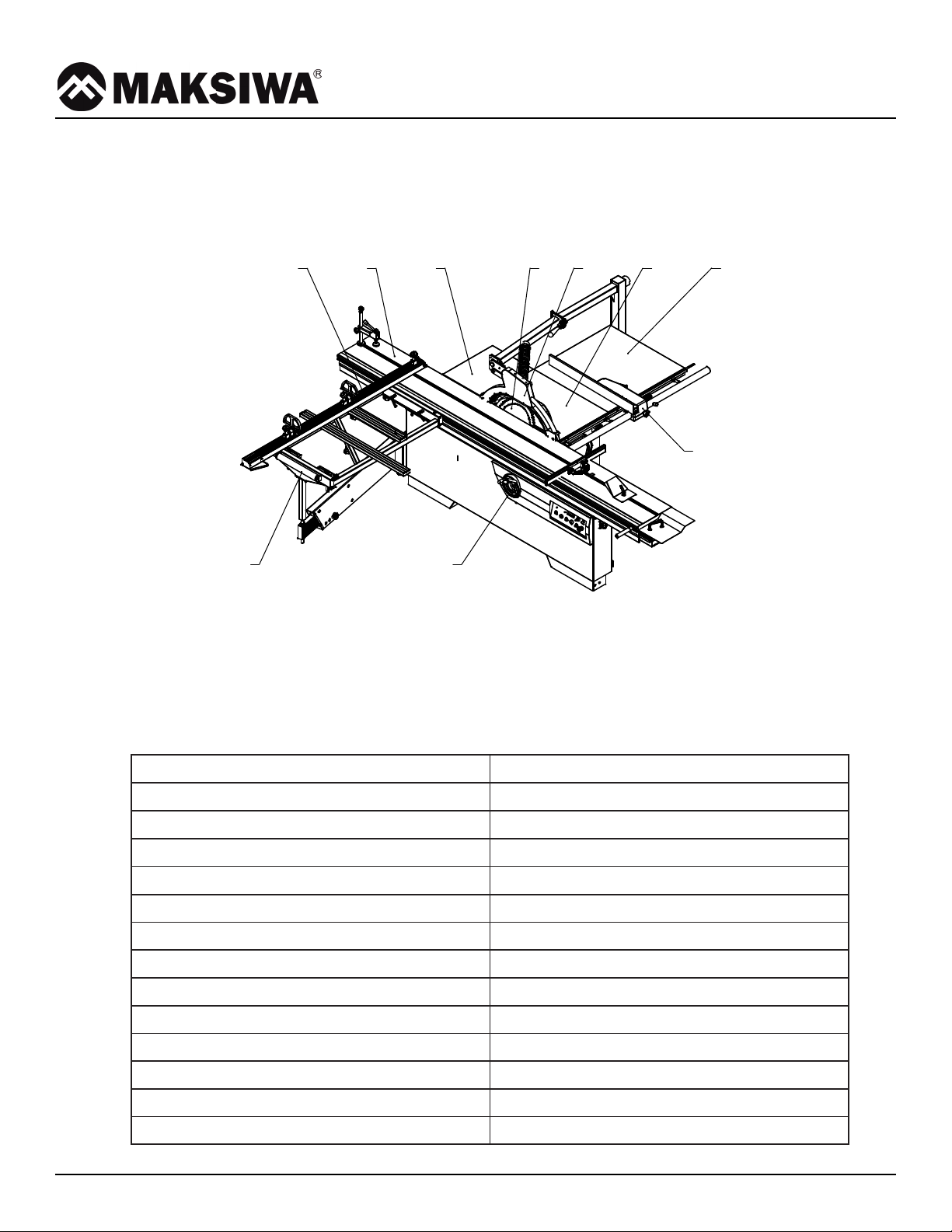
3.1 Main Components
3.2 Technical Specifi cation
3.1 Main Components
Motor Voltage 220V-60Hz/3x220V-60Hz
Main motor power 5HP
Scoring motor power 1HP
Main blade diameter 315-30mm
Main blade speed 4000rpm
Scoring blade diameter 120-20mm
Scoring blade speed 8000rpm
Blade tilt 0~45°
Main table size 800x530mm
Right extension table size 800x820mm
Max.rip capacity 1250mm
Max.depth of cut 95mm@90° | 67mm@45°
Sliding table size 3200x375mm
Square sliding table size 1200x630mm
9 - Tilting handwheel
10 - Rip fance assemnly
1
2
5
67
8
1 - Right extension table
2 - Main table
3 - Blade guard assembly
4 - Blade
9
10
3
4
5 - Rear extension table
6 - Sliding table
7 - Telescopic fence
8 - Square sliding table

11
3 Description
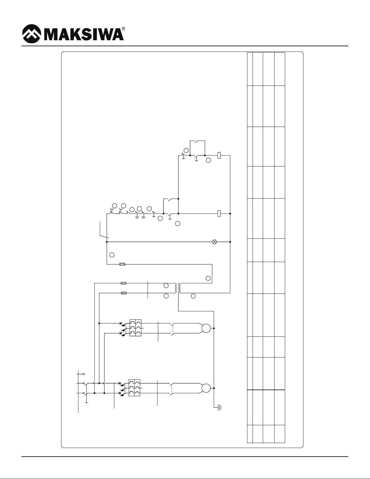
3.3 Electrical Connection
- Electrical installation should be carried out by competent, qualifi ed personnel.
- The mains connection should be made using the terminal box.
- Replacement of the power supply cable should only be done by a qualifi ed electrician.
- Connect the main leads to a standard 220V±10% (60Hz+1%Hz) electrical supply which has protection devices
of under-voltage, over-voltage, over-current the main connection must have maximum 25A time-lag fuse.
WARNING
Indicates imminent risks which may cause serious injury to the operator or other persons.
Be careful and scrupulously follow the instructions.
Indicates imminent risks which may cause serious injury to the operator or other persons.
Be careful and scrupulously follow the instructions.
12
QS1
PE
N
L
U2
M2
KM2
Q1
1L11L21L3
Q2
F1 F2
KM1
1
11
12
13
16
17
18
24V
Q1
SA2
0
SA1
V2
V1
KM2
M1
U1
1L31L11L2
21
14
ST1
SS
Q2
SB1
22
KM2
ST2
SB2
20
15
KM2KM1
HL
19
L1
N
14AWG
14AWG
14AWG
16AWG
16AWG
18AWG
Code
Type
Description
Code
Type
Description
Code
Type
Description
Code
Type
Description
KM1
3RT60251AC20
Contactor
Q2
3RV6011-1FA15
Overload protector
SA1,SA2
HY57B-02
Emergency Button
HL
AD16
Power Light
KM2
3RT60231AC20
Contactor
SB1,SB2
M22-D-G-X1-K10
Start Button
F1,F2
FNQ-1A
1A Fuse
Q1
3RV6021-4BA15
Overload protector
ST1,ST2
M22-D-R-X0-K01
Stop Button
TR
BK-100-230V-24V-A
Transformer
3 Description

13
3 Description
L1 L2 L3
PE
QS1
Q1 Q2
KM1 KM2
1L1 1L2 1L3
U1
V1
W1
U2
V2
W2
1L1 1L2 1L3
F1 F2
Q1
Q2
SA1
SA2
ss
ST1
SB1
KM1
ST2
SB2
KM2
KM1 KM2
HL
M
3~
M
3~
M2M1
24V
13
21
14
15
17
18
19
20
22
11
12
1 0
16
220V,60Hz,4KW
TR
代号 型号
Description
KM1
3RT60251AC20
Contactor
KM2
3RT60231AC20
Contactor
Q1
3RV6021-4BA15
Overload protector
Q2
3RV6011-1FA15
Overload protector
F1/F2
CHM1DU
1A Fuse
TR
BK-100-230V-24V-A
Transformer
SB1/SB2
M22-D-G-X1-K10
Start Button
ST1/ST2
M22-D-R-X0-K01
Stop Button
SA1/SA2
HY57B-02
Emergency button

14
3 Description
3.4 Noise Level
No Load Load
Sound Pressure Level < 80.4cB (A) < 85.7dB (A)
Sound Power Level < 98.1dB (A) < 100.7dB (A)
Associated uncertainty K=4dB
Measurement made in accordance with EN ISO 3746:1995 and EN ISO 11202:1995
The noise levels measured are emission levels and not necessarily the safe working level. Although there is
a correlation between the emission levels and the exposure levels, this cannot be used reliably to determine
whether or not further precautions are required. The factors which affect the actual level of operator exposure
include the duration of exposure, the ambient characteristics and other sources of emission, for example, the
number of machines and other adjacent machining. The permitted exposure values may also vary from country
to country. Nevertheless, this information allows the user of the machine to better evaluate the dangers and risks.
Other factors which reduce exposure to noise are:
• correct tool choice
• tool and machine maintenance
• use of hearing protection systems (e.g. headsets, earplugs,...)
WARNING
Indicates imminent risks which may cause serious injury to the operator or other persons.
Be careful and scrupulously follow the instructions.
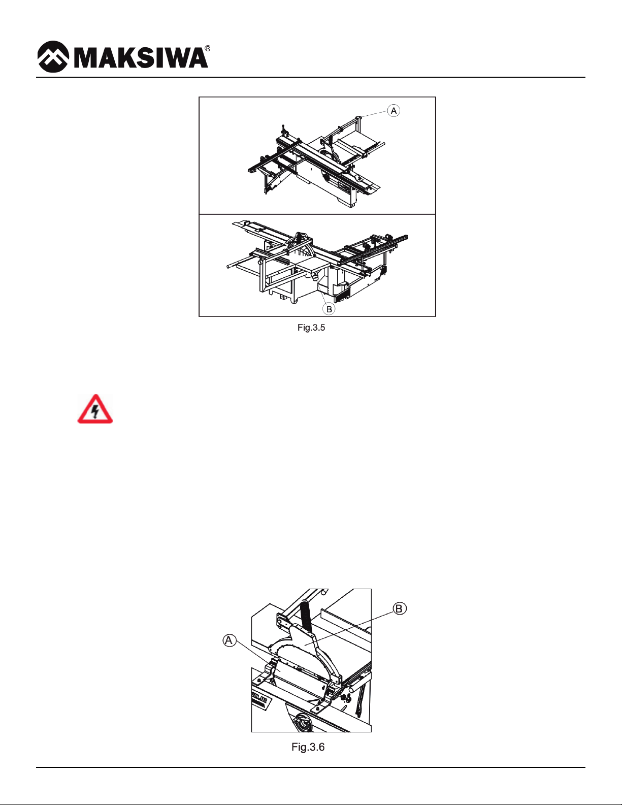
3.5 Dust Extraction
Proper suction eliminates the risks of dust inhalation and aids better functioning of the machine. The tables
list the minimum air fl ow and speed values referenced to each single suction operation.The related pressure
drop at the dust port is 530Pa.
Ensure that the suction system guarantees these values at the hood-houth connection point. (Fig.3.5)
Suction mouth diameter:
A - Blade guard ...... ø100 mm(ø76mm)
B - Body dust suction ...... ø100 mm(ø120mm)
Indicates imminent risks which may cause serious injury to the operator or other persons.
Saw
Upper hood Lower hood
Air fl ow 140 cu.m/h 690 cu.m/h
Minimum air speed 20 m/s
15
3 Description
Connect the mouths to the suction system with fl exible tubes of adequate diameter. Tighten with clamps. The
tube must be positioned in such a way so as not to obstruct the operator during machining.
WARNING
Indicates imminent risks which may cause serious injury to the operator or other persons.
Be careful and scrupulously follow the instructions.
3.6 Safety Devices
The machine is equipped with the following safety devices: (Fig.3.6)
A - Safety Switch.
Stops the machine if the guard D is opened to perform operations on the blade.
B - Saw blade guard
Emergency Switch
When the button is pressed, the power will been cut immediately. It is a mechanical-operated push-button.
Reset this button by turning it clockwise.
Indicates imminent risks which may cause serious injury to the operator or other persons.
Be careful and scrupulously follow the instructions.

16
4 Installation
4 Installation
CAUTION
Assembly need to be done by an experienced and trained person.
4.1 Contents of Package
• The machine is supplied partly assembled. Prior to use, further assembly is required.
• When unpacking the machine the following components are included for the initial assembly.
•If any parts are missing, do not attempt to assemble the machine; plug in the power cord, or turn the switch
on until the missing parts are obtained and properly installed.
Total two carton:
1. Fixed blade cover Assembly
2. Rear extension table
3. Square sliding table
4. Telescopic fence assembly
5. Frame assembly
6. Guide rail
7. Scale bracket
8. Rip fence assembly
9. Right extension table
10. Slide table(packed separately)

17
4 Installation
4.2 Lifting and Unloading
WARNING
Lifting and handing should only be carried out by skilled personel specially trained to execute this kind of
operations. During loading and unloading, avoid knocks to prevent damages to persons and things. Make sure
no one is standing under the overhung load and/or within the bridge crane working range during machine lifting
and handing.
Lifting and handing should only be carried out by skilled personel specially trained to execute this kind of
Lifting may be carried out by bridge crane or self-propelled
lift truck. Before starting the manoeuvres, free the machine
of all the parts used for transport or Packaging that have
remained on the machine. Check that the capacity of the
lifting equipment is adequate for the gross weight of the
machine indicated Fig.4.2.
If hoisting is carried out with a lift truck, proceed as follows:
• adjust the width of the forks A to 550 mm
•Insert forks A as in the fi gure in correspondence to
name plates E ensuring that these are wedged against
the back of the rear feet D.
•If a bridge crane or a crane is available,proceed as
follows:
•provide two slings B of suitable length and capacity
(Belts minimum length 4000mm)
•lift the slings and position them as is shown in the
Fig.4.2
•fasten the slings to the bridge crane C having adequate
lifting power
•move the bridge crane by small steps to allow the
slings B to settle, until optimum stability conditions are
reached – lift carefully and slowly, without causing the
load to swing, and place the machine in the selected
setting
•remove the protective wax coat from all tables and
unpainted surfaces, using kerosene or its derivative
products. Do not use any solvent, petrol or gas oil,
which might dull the paint or oxidate machine parts.

18
4.3 Installation Zone Characteristics
WARNING
It is prohibited to install the machine in explosive environments.
The installation zone must be selected evaluating the work space required depending on the dimension of the
pieces to be machined,and taking into account that a free space of at least 800 mm must be left around the
machine.It is also necessary to check the fl oor capacity and its surface, so that the machine base is evenly
resting on its four supports.A power outlet and a chip-suction system connection shall be close to the selected
machine setting and it must be conveniently lighted (luminous intensity: 500 LUX).
FIXING TO THE FLOOR
1. The machine must be fi xed to the fl oor.
2. -Use bolt / nut A to level the feet to ensure machine is well located.
3. -Put expansion bolts D (not supplied) into ground, use washer / lock washer C and hex nut B to fasten
the bolts.
4 Installation
19
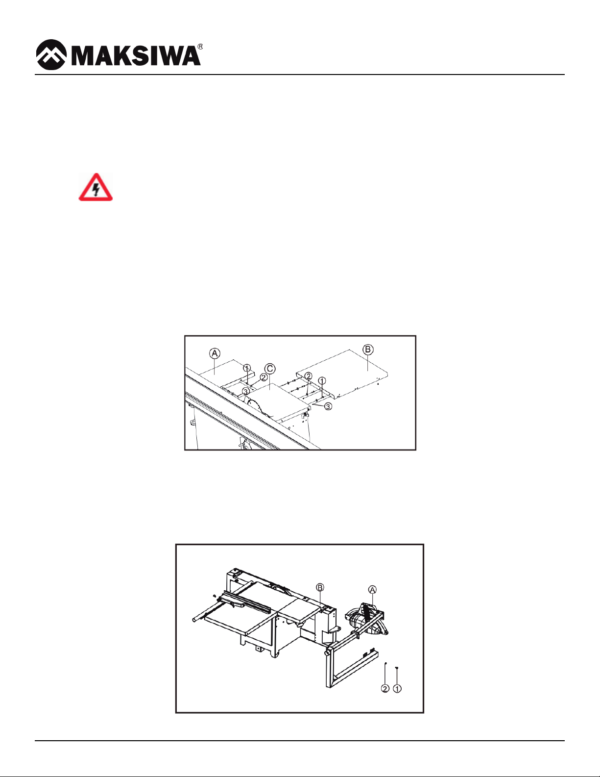
4.4 Install of Loose Parts - Introduction
A few elements will be disassembled from the machine main structure due to packaging and shipping
requirements. These loose parts should be installed as follows.
WARNING
Please tighten all bolts and nuts absolutely. Otherwise, may cause machine wobble or serious injury
to the operator or other persons.
4.4.1 INSTALL EXTENSION TABLE
Tools Required for Assembly:
• Wrench 16mm
• L Wrench 6mm
• Install Extension tables A to main table C with bolt 1 and washer 2.
• Install set screw 3 for micro-adjustment.
4.4.2 INSTALL BLADE GUARD AND HOSE SUPPORT ROD
Tools Required for Assembly:
• Wrench 18mm
• Install blade guard A on body B with parts 1 and 2.
4 Installation
Fig. 4.4.1
Fig. 4.4.2

20
4.4.4 INSTALL SQUARE SLIDING TABLE
• Put the square sliding table C into the slot of sliding table A.
• Tools Required for Assembly: 10mm Allen wrench
• Pass B, C, and D through E and fix them on A (don't fix them too tightly, there are four sets)
• Adjust the slider to the alignment bolt, then tightened the Allen bolts “
• Put the support rod D into the hole of square sliding table C and the hole on support arm E.
• Lock the handle B.
4.4.5 INSTALL TELESCOPIC FENCE
• Put the pin A of telescopic fence intothe hole which is on the square slidingtable, and mount the handle B to the pin.
• Lock the knob C for stable tighting.
• The Knob D is designed to micro-adjust perpendicularity between telescopic fence and blade.
4 Installation
4.4.3 RIP FENCE PRECISION ADJUSTMENT
B
C
D
E
A
Fig.4.4.4
Fig.4.4.5
Fig.4.4.3
Other manuals for BMS.3200.IR
2
Table of contents
Other MAKSIWA Power Tools manuals


Popular Power Tools manuals by other brands


Allied
Allied HO-PAC 4000 SAFETY, OPERATION, MAINTENANCE AND PARTS MANUAL

Scheppach
Scheppach MTC53-4BP Translation from the original instruction manual

Central Machinery
Central Machinery 34542 Assembly and operating instructions

Circassia
Circassia NIOX VERO user manual

Oregon
Oregon 552225 owner's manual

Fein
Fein AFMM 18 QSL instruction manual

King Canada
King Canada 8101S instruction manual

Home Accents Holiday
Home Accents Holiday 36681 instructions

Parkside
Parkside PUD 30 A1 operating instructions

RS
RS 477-517 Instruction leaflet

Palmgren
Palmgren 80177 Operating manual & parts list

JB GURY
JB GURY UNIVERSAL Comet CENTURY Parts and service manual