MAKSIWA DE.1200/3 User manual

1
DE.1200/3
INSTRUCTION MANUAL
Wood Jointer
Attention: Read this manual before using your machine.

2
Important information you should know:
• The images in this manual are illustrative and are
meant to demonstrate the correct operation of your
product, there may be small changes in relation to the
images.
On-Line Support: In our YouTube
Channel you will find several videos
that will help you whit Maksiwa´s
machines. To use the QRCODE.
CAUTION:
WHEN DOING MAINTENANCE, REPLACE ONLY
WITH IDENTICAL PARTS. Repair or replace damaged
wiring.
• THIS JOINTER MUST BE CONNECTED TO A
GROUNDED WIRING SYSTEM or to a system with
an equipment-grounding conductor. In malfunction
event, grounding provides a path of least resistance
for electric current to reduce the risk of electric
shock. This wood jointer is equipped with an electric
cord having an equipment grounding conductor
and a grounding plug. The plug must be connected
into a matching outlet provided – if it will not fit the
outlet; have the proper outlet installed by a qualified
electrician. Improper connection of the equipment-
grounding conductor can result in a risk of electric
shock and/or malfunction. If repair or replacement of
the electric cord or plug is necessary, do not connect
the equipment-grounding conductor to a live terminal.
Check with a qualified electrician or service personnel
if the grounding instructions are not completely
understood or if in doubt as to whether the wood
jointer is properly grounded. Use only 3-wire extension
cords that have 3-prong grounding plugs and 3-pole
receptacles that accept the wood jointer´s plug.
• REPAIR OR REPLACE A DAMAGE OR WORN CORD
IMMEDIATELY. When servicing use only identical
replacement parts.
• USE PROPER EXTENSION CORD. Make sure your
extension cord is in good condition. When using an
extension cord, be sure to use one heavy enough
to carry the current your wood jointer will draw.
undersized cord will cause a drop in line voltage
An undersized cord will cause a drop in line voltage
resulting in loss of power and overheating. For cord
length of up to 50 feet, use a cord of 14 gauge. For a
cord length of 50 to 100 feet, use a cord of 12 gauge.
A cord length over 100 feet is not recommended. If in
doubt, use the next heavier gauge. Smaller the gauge
number, heavier the cord.
• This jointer is intended for use on a circuit that
has an outlet similar to the one illustrated in Sketch
A. The jointer has a grounding plug similar to the
plug illustrated in Sketch A. Make sure the jointer is
connected to an outlet having the same configuration
as the plug. No adapter is available or should be
used with this wood jointer. If the machine must be
reconnected for use on a dierent type of electric
circuit, the reconnection should be made by qualified
service personnel; and after reconnection, the
wood jointer should comply with all local codes and
ordinances.
• Keep a clean work surface. Cluttered areas and work
surfaces are invite accidents.
• Do not use the wood jointer in hazardous
environments. Do not use machine in damp or wet
locations or exposed to rain. Keep well-lit work area.
• Keep children away. Visitors should be kept safe
distance from work area.
• Make the workplace childproof making use of
padlocks, master keys or removing the ignition key.
• Do not force tool. It will perform the job better and
safer for the intended use.
• Keep children away. Visitors should be kept safe
INSTRUCTION MANUAL
READ ALL INSTRUCTIONS
GROUNDING INSTRUCTIONS
SAFETY INSTRUCTIONS
FOR ALL EQUIPMENTS
WARNINGS

3
distance from work area.
• Make the workplace childproof making use of
padlocks, master keys or removing the ignition key.
• Do not force tool. It will perform the job better
and safer for the intended use.
• Use appropriate equipment. Do not wear loose
clothing, gloves, chains, rings, bracelets or other
accessories that could become caught in moving
parts.
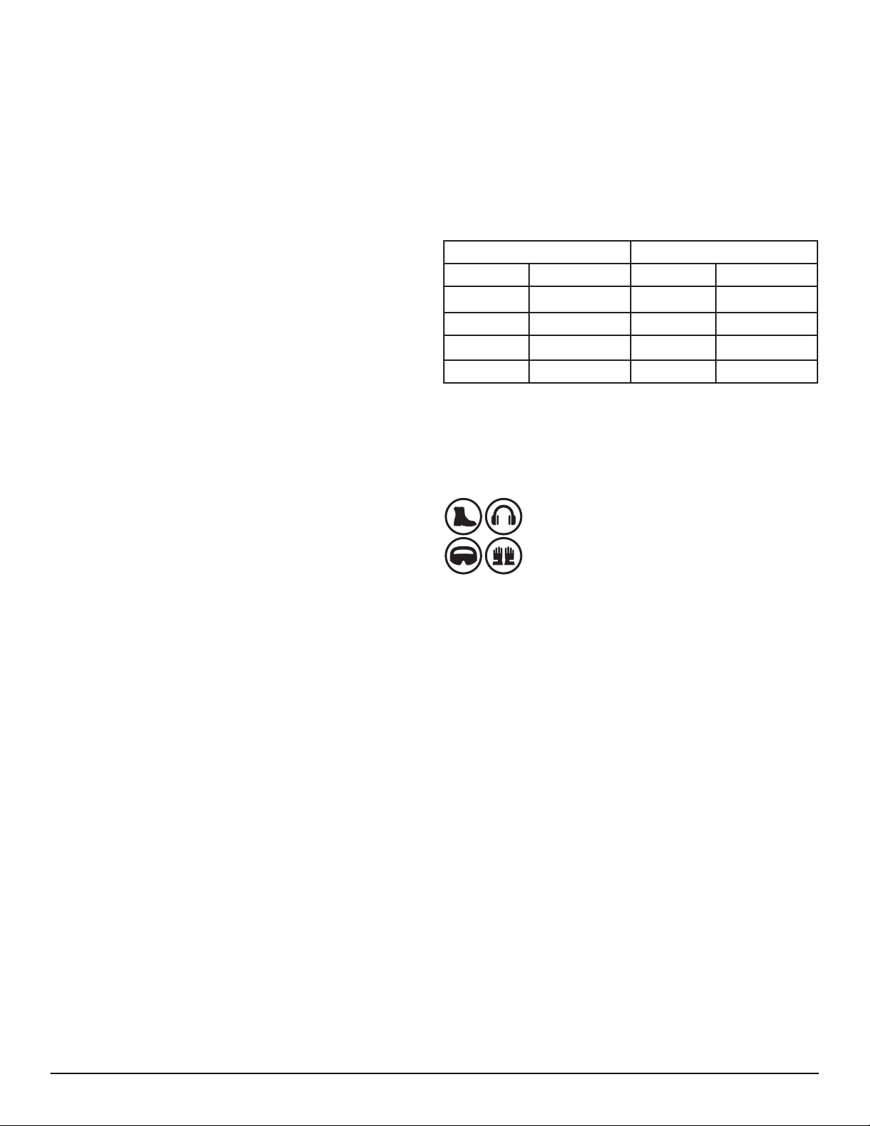
• It is recommended wearing shoes with non-slip soles.
Use protection for the hair in order to hold them.
• Always wear safety glasses. Also use hearing
protection.
• Do not overreach on the equipment. Maintain
balance and feet in comfortable position at all times.
• Keep all tools in order. Keep tools sharp and clean for
better and safer performance. Follow the instructions
for lubricating and changing accessories.
better and safer performance. Follow the instructions
for lubricating and changing accessories.
• Unplug the machine before servicing or changing
accessories such as scissors, cutters etc.
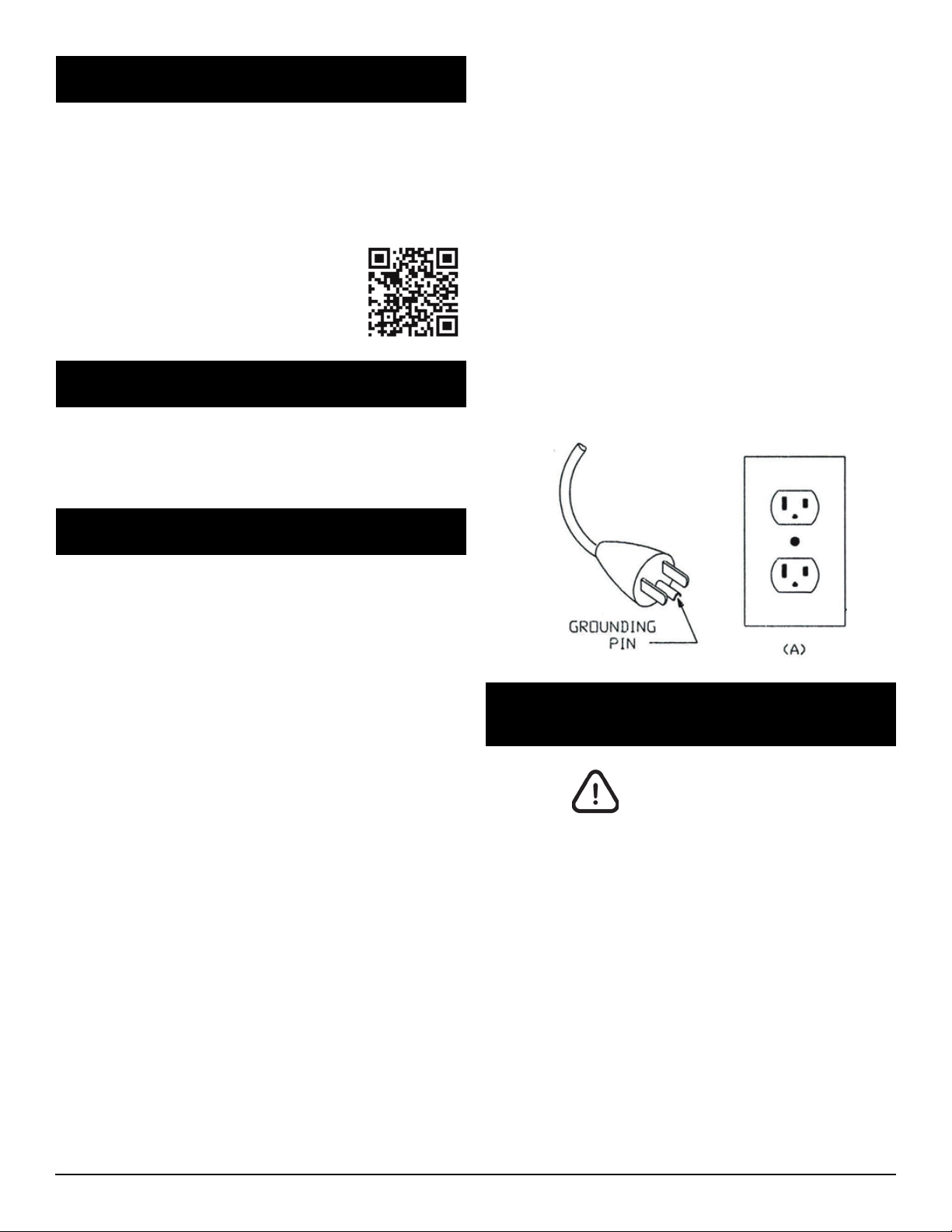
• Reduce the risk of unintentional starting. Ensure
that the switch is in the “OFF” position (o) before
connecting the wire to the plug.
• Use recommended accessories. See the instruction
manual to check recommended accessories. Improper
use of accessories may cause risk of injury to persons.
• Never step on the machine. May occur serious
accident if the machine is dented or if parts are
accidentally touched.
• Check for damaged parts. Before continuing the use
of wood jointer, a guard or other part that is damaged
should be examined carefully to determine its proper
operation and perform its function properly. Check
the alignment of moving parts, breakage of parts,
mounting and any other condition that may aect
its operation. Any part that is damaged should be
repaired or replaced immediately. Do not use the tool
if the switch does not turn on or o.
• Never leave a running tool unattended. Turn o the
ignition key.
• The engine of this machine can emit sparks, and
explode flammable gases.
• Extension cables. Make sure your extension cord is
in good condition. When using an extension, be sure
of their ability to transmit the electrical current used
by your product. An undersized cord will cause drop
in voltage resulting in loss of power and overheating.
The following table shows the correct size to be used
depending on the cable diameter and amperage rate.
If in doubt, use a cable with a higher level of capacity.
IMPORTANT: Do not use an extension cord with length
above 20 meters.
Cable 2 wires Cable 3 wires
Ø (mm²) Amperage Ø (mm²) Amperage
0,5 90,5 8
1,0 13 1,0 12
1,5 16,5 1,5 15
2,5 23 2,5 20
Additional safety rules for wood jointer:
CAUTION: FAILURE TO ATTEND THESE WARNINGS
MAY RESULT IN PERSONAL INJURY AND SERIOUS
DAMAGE TO THE MACHINE.
• Always use safety glasses. Also use face or dust mask
if cutting operation is dusty. Everyday eyeglasses only
have impact resistant lenses, they are NOT safety
glasses.
• Keep guards in place and working order.
• Protect the electric power supply line with at least a
20 amp fuse or a circuit breaker switch.
• Make sure that the advance is turning in the right
direction.
• Make sure that the knobs and screws are properly
tightened and safe before starting any operation.
• Keep sharp tools.
• Keep vents free of chips or dirt engines.
• Keep hands away from moving or sharp parts.
• Turn o the machine and unplug the power cord
before maintenance or adjustments of the tool.
• Support long pieces with a clamping device for
wood.
ALWAYS USE PROPER PROTECTIVE
EQUIPMENTS TO OPERATE THIS
MACHINE.

4
parts and will need to know where they are.
Especifications
Table Lenght: 47-2/8”
Table Widht: 6”
Max. depth capacity: 1/8”
Speed: 5,200 RPM
Number of knives: 3
Knife dimensions:
158 x 18 x 3 mm (6-13/64” x 45/64” x 3/32”)
Fence tilt: 45° to 90°
Motor: 1 HP - 1 - 3 Phases
Volts/Amps:
1 Phase: 127 V - 16 A or 220 V - 8 A
3 Phases: 220 V - 3,5 A or 380 V - 2,1 A
Weight: 267 Lbs
Transport and Installation
By ergonomic issues, this equipment must be carried
by at least two people, holding by the handles located
on the sides of the box.
For packaging purposes, the machine is not fully
assembled. If you notice any damage caused by
transportation, while you open the package, notify
your supplier immediately. Do not operate the
machine.
Dispose the packaging in a friendly way with the
environment.
The wood jointer is designed to operate indoors and
should be placed on a firm, stable and level surface.
• Do not attempt to operate the machine in another
voltage beyond designated.
• Do not use larger or smaller tools than recommended.
• Do not apply lubricant to the tools during use.
• Do not operate without some parts of the machine.
• Do not put your hands less than 4in from the shaft.
• Do not put your hands in closed parts of the machine
unless it is turned o and unplugged.
• Do not use lubricants or cleaners (particularly sprays
and aerosols) in the vicinity of the plastic guard. The
polycarbonate material used in the guard is sensitive
to certain chemicals.
WARNING: Some dust created by the act of sanding,
cutting, grinding, drilling and other construction-
related activities contains chemicals that can cause
cancer, birth defects or other reproductive harm.
Some examples of these products are: Lead-based
paint; crystal silica bricks, concrete and other masonry
products; and arsenic and chromium from chemically
treated wood.
CAUTION: Do not connect the unit to the power outlet
until all instructions have been read and understood.
Always tighten the adjustment tabs before using the
machine. Think: “I can prevent accidents”.
Do not operate the machine unless the guards are in
their proper places. Always use protective goggles.
Electrical connection
The wood jointer has engine 1-phase 110V. To avoid
burning risk, check the voltage of your outlet before
starting the machine. If necessary make the change of
your power with the help of a specialist.
Ensure that your power supply is in accordance with
the designated on the board. A 10% decrease in voltage
or more will cause loss of power and overheating. All
equipment MAKSIWA are tested at the factory. If this
machine does not work, check the electricity supply.
Check the compatibility of your outlet and plug the
machine. Do not do patches and adaptations.
To avoid electrical shock and damage to the equipment
always ground the machine.
Familiarization
Put the machine on a smooth and flat surface. Check
the pictures and watch the descriptions to familiarize
yourself with its components. The next section will
deal with the necessary adjustments for the proper
functioning of the machine. You should know these

5
To mount the jointer to the stand:
1. Remove the outer cover of the cabinet.
2. With the help of an assistant, lift the jointer onto
the cabinet.
3. Align the three bolt holes on the jointer with the
three holes on the cabinet.
4. Using the 8 mm hex wrench, secure the jointer
to the cabinet with the M10-1,5 x 20 cap screws, flat
washers, and look washers.
NOTE: Reach through the dust vent for access to the
forward mounting hole as shown in next figure.
2. Lift the motor upward far enough to allow the
V-Belts to be placed around the cutterhead pulley
and motor pulley.
3. Carefully allow the motor to slide downward
tensioning the V-Belts with the weight of the motor.
4. Looking from the top, sight down the V-Belts and
pulleys and check to see that the pulleys are parallel
and aligned with each other.
- If the pulleys are aligned, tighten the motor mounts
loosened in Step 1 and go to Step 7.
- If the pulleys are not aligned, perform Step 5 e 6.
5. Remove the V-Belt, loosen the set screws on the
end of the motor pulley, and align the motor pulley
with the cutterhead pulley. If needed, the motor can
be loosedned and moved in or out to bring the motor
pulley into alignment with the cutterhead pulley.
6. Tighten the set screws, replace the V-Belts and
repeat Step 4. Belts should be perfectly parallel and
aligned as shown in next figure.
7. Replace the access cover on the cabinet.
To Install the V-Belt
1. Using a 13 mm wrench, loosen, but DO NOT remove
the motor mount bolts
Mounting Holes
Cutterhead Cutterhead
Pulley
Motor Motor Pulley
Setscrew
Alignment

6
To install the carriage mounting bracket:
1. Align the locating pins on the back of the carriege
mounting bracket with the sockets on the jointer
table.
To install the fence carriage assembly:
1. Use two M8-1,25 x 20 cap screws, lock washers and
flat washers to secure the fence carriage assembly to
the carriage mounting bracket.
2. Use two M8-1,25 x 20 cap screws, lock washers and
flat washers to secure the fence assembly to the fence
carriage assembly.
3. Thread the fence tilting handles into the fence.
To install the cutterhead guard:
1. Wind the torsion spring knob back counterclockwise
a half turn and slide the guard shaft into the casting
shown in next figure. Make sure the slot on the
cutterhead guard shaft fits over the pin that sits inside
the spring knob barrel.
2. Test the guard by pulling it back and letting go.
2. Tighten the carriege mounting bracket to the
jointer table with the cap screws, lock washers and
flat washers.
Locating Pins
Sockets
Torsion Spring Knob

7
To install the dust port:
NOTE: if you choose to not use a dust collection
system, don’t install the dust port. Chips will build up
inside the cabinet and clog.
1. Place the dust port over the dust vent in the side of
the cabinet.
2. Use the four M5*10 Phillips head screws and flat
washers to secure the dust port to the cabinet.
To install the power switch e support arm:
1. Install the support arm with the M8*16 cap screws
and flat washers as shown in next figure:
To install the handwheel:
1. Remove the screw and flat washer already mounted
to the handwheel shaft.
2. Secure the handwheel to the shaft with the hardware
removed in Step 1.
Setting Outfeed Table Height:
The outfeed table must be level with the knives when
they are at top-dead-center. This adjustment has been
made at the factory but should be checked again
before operating your jointer. This adjustment will also
have to be made any time you perform maintenance
on the cutterhead or knives.
To set the outfeed table height:
1. Place a straightedge on the outfeed table so it
extends over the cutterhead.
2. Rotate the cutterhead pulley until one of the knives
is at top-dead-center (TDC), illustrated in next figure:
3. Raise or lowwer the outfeed table until the knife
just touches the straightedge.
4. Lock the outfeed table in next figure (outfeed table
lock):
3. Attach to dust collection system.
Top Dead
Center
Straightedge
Outfeed Infeed

8
Starting the machine:
1. Read the entire instruction manual.
2. make sure the cutterhead guard is installed and
correctly adjusted.
3. Make sure all tools and foreign objects have been
removed from the machine.
4. Connect your machine to the power source.
5. Press the START button to turn the machine ON
- The jointer should run smoothly with little or no
vibration;
- Immediately stop the jointer if you suspect any
problems and to troubleshoot/fiz any problems
before starting the jointer again.
Recommended Adjustments
For your convenience the adjustments listed below
have been performed at the factory and no futher
setup is required to operate your machine.
However because of the manu variables involved with
shipping, we recommend that you at least verify the
following adjustments to ensure the best possible
results from your new machine.
Step-by-step instructions for these adjustments can
be found in SECTION 4.
Factory adjustments that should be verified:
1. Knife Settings.
2. Depth Scale Calibration.
3. Fence Stop Accuracy.
Schedule Maintenance
For optimum performance from your machine. follow
this maintenance schedule and refer to any specific
instructions given in this section.
Daily
- Vacuum all dust on and around the machine.
- Wipe down tables and all other unpainted cast iron
with a metal protectant.
Monthly Check
- V-Belt tension, damage or wear;
- Clean/vacuum dust buildup from inside cadinet and
o motor.
V-Belt
To ensure optimim power transmission from the motor
to the blade, the V-Belt must be in good condition
(free from cracks, fraying and wear) and propoerly
aligned and tensioned.
Cleaning
Cleaning the DE.1200/3 is relatively easy. Vacuum
excess wood chips and sawdust, and wipe o the
remaining dust with a dry cloth. If any resin has built
up, use a resin dissolving cleaner to remove it. Treat
all unpainted cast iron and steel with a non-staining
lubricant after cleaning.
Unpainted Cast Iron
Protect the unpainted cast iron surfaces on the table
by wiping the table clean after every use this ensures
moisture from wood dust does not remain on bare
metal surfaces. Keep tables rustfree with regular
applications.
Lubrication
Since all bearings are sealed and permanently
lubricated, simply leave them alone until they need to
be replaced. DO NOT lubricate them.
Table ways and the fence assembly should not
be lubricated. If the tables appear to be stuck,
disassemble and clean any foreign materials from the
ways. Re-assemble and reset the gibs.

9

10

11
Inspecting Knives
The height of the knives can be easily and quickly
inspected with the knife setting jig. This inspection
will ensure that the knives are set in the cutterhead as
they should be. Usually this is done before calibrating
the outside table or when troubleshooting.
To inspect the knives:
1. Disconnect the jointer from the power source!
2. Remove the cutterhead guard or block it out of the
way.
3. Lower the infeed table to the 1/2” scale mark.
4. Place the knife jig on the cutterhead, directly over a
knife, as shown in next figure.
To set the knives
1. Disconnect the jointer from the power source!.
2. Remove the cutterhead guard from the table and
lower the infeed and outfeed tables as far as theu
go. This will give you unrestricted access to the
cutterhead.
3. Remove the cabinet cover to expose the V-Belt.
4. Use the V-Belt to rotate the cutterhead to access
the cutterhead knives.
5. Loosen the cutterhead gib bolts, starting in the
middle, and alternating back and forth until all of the
gib bolts are loose, but not falling out.
NOTE: If this is the first time you are setting the
knives, remove the gib and knive from the cutterhead.
Decide which adjustment option you are going to
use between the jack screws and the springs. If you
decide to use the jack screws, remove the springs
from the cutterhead. if you decide to use the springs,
you can just thread the jack screws completely into
the cutterhead so they will not get lost. Replace the
gib and knife.
6. Position the knife gouge over the knife as shown in
next figure and loosen the gib bolts until the knife is
completely loose.
7. Jack Screws - Using a 3 mm hex wrench, find the
jack screws through the access holes in the cutterhead
and rotate the jack screws to raise or lower the knife.
When the knife is set correctly, it will barely touch the
middle pad of the knife setting jig. Snug the gib bolts
tight enough to just hold the knife in place. Repeat
Steps 5-7 with the rest of the knives.
5. Carefully inspect how the jig touches the cutterhead
and the knife.
- If both outside legs of the jig sit firmly on the
cutterhead and the middle pad just touches the knife,
then that knife is set correctly. (Repeat this inspection
with the other knives).
- If the jig does not sit firmly on the cutterhead and
touch the knife edge as described, then reset that
knife. (Repeat this inspection with the other knives).
Setting Knives
Setting the knives correctly is crucial to the proper
operation of the jointer and is very important in
keeping the knives sharp. If one knife is higher that
the others, it will do the majority of the work, and
thus, dull much faster that the others.
The knife jig included with the jointer is designed to
set the knives at the correct height.

12
8. Rotate the cutterhead to the first knife you started
with. Slightly tighten all the gib bolts, starting at
the ends and working your way to the middle by
alternating left and right. Repeat this step on the rest
of the knives.
9. Final tighten each gib bolt.
10. Adjust the outfeed table to match the new knife
heights.
Calibrating Depth Scale
The depth scale on the infeed table can be calibrated
or “zeroed” if it is not correct.
To calibrate the depth scale
1. Set the outfeed table height as described in the
Setting Outfeed Table Height su-section.
2. Place a straightedge across the infeed and outfeed
tables.
3. Adjust the infeed table until it is level with the
outfeed table.
Setting Fence Stops
The fence stops are adjustable nuts and bolts that
simplify the task of adjusting the fence to 45° inward,
90°, and 45° outward (135°).
To set the 45° inward fence stop:
1. Using a 45° square, adjust the fence to the 45°
inward position:
2. Loosen the jam nut shown:
Infeed table adjusted even with outfeed
table and knife at TDC.
Adjusting fence 45° inward.
45° inward fence stop jam nut
Depth-of-cut pointer adjusted to “0”
position.
Straightedge
Outfeed Infeed
4. Using a screwdriver, adjust the scale pointer exactly
to “0”.
3. Adjust the 45° inward fence stop nut until it makes
contact with the back of the fence bracket.
4. Retighten the jam nut loosened in Step 2 and
rechech.
To set the 90° fence stop:
1. Flip the 90° swing stop the position shown next:
Fence Stop Nut
Jam Nut

13
Swing Stop
Jam Nut
Fence Stop Bolt
90° swing stop engaged.
45° outward fence stop jam nut
Adjusting fence 45° outward.
2. Using a 90° square, adjust the fence to the 90°
position using the fence stop bolt and jam nut:
3. Loosen the jam nut on the 90° fence stop bolt.
4. Adjust the 90° fence stop bolt until it makes contact
with the 90° swing stop.
5. Retighten the jam nut loosened in Step 3 and
recheck.
To set the 45° outward fence stop:
1. Flip the 90° swing stop out of the way as shown in
next figure.
2. Using a sliding bevel adjusted to 135°, adjust the
fence to the 135° (45° outward) position.
3. Loosen the jam nut on the 45° outward fence stop
bolt.
4. Adjust the 45° outward fence stop bolt until it
makes contact with the back of the fence.
5. Retighten the jam nut loosened in Step 3 and
recheck.
Adjusting Gibs
The function of the table gibs is to eliminate excessive
play in the table movement. The gibs also control how
easy it will be to move the tables up and down.
To adjust the table gibs:
1. Using a 100mm wrench, loosen the two outfeed
table gib nuts on the side of the jointer base.
2. Using a 3mm hex wrench, evenly tighten the gib
stescrews a small amount, then check the table by
moving it up and down. Adjust the setscrews as needed
until the friction of the table movement is balanced
between minimal play and ease of movement.
NOTE: Tighter gibs reduce play but make it harder to
adjust the tables.
3. Repeat Steps 1-2 with the other table.
4. Set the outfeed table height as described in stting
Outfeed Table Height.
Swing Stop
Gib Setscrews
Gib Nuts

14
WARRANTY TERM
The MAKSIWA assures the owner of his equipment,
identified by the date of issue of the purchase invoice,
a warranty of two (2) years, as follows:
1. The warranty period begins on the date of the
commercial invoice.
2. Within the warranty period, the hand labor and
the components replaced by manufacturing defect
will be provided for free as long as duly proved by
Maksiwa Service.
3. Third-party manufacturing equipment that makes
up the MAKSIWA equipment (such as motors,
electrical equipment, belts etc.) are subject to the
terms and conditions of warranty of their respective
manufacturers.
4. In case of exchange for the warranty, please return
the defective part for the manufacturer urgently.
5. Costs and risks of transport will be by the machine
owner.
6. Equipment installation expenses and workplace
adaptations are due to the machine owner.
7. When you notice any defect or malfunction when
receiving the equipment, get in touch immediately
with the manufacturer or resale. Do not turn it on.
8. Not included in this warranty technical visits aimed
at cleaning or adjustments caused by wear, resulting
from normal use of the equipment.
9. The warranty does not cover problems caused by
mistreatment, carelessness, misuse or inappropriate
use of the functions designed for this equipment in
this manual, as well as poorly executed operations by
untrained operators to operate it.
10. The MAKSIWA is not responsible for lost
productivity, direct or indirect damages caused to
the owner of the equipment or to third parties, or any
other expense, including lost profits.
11. Even under warranty, you may lose its validity as
follows:
a) Application of non-original components;
b) Alteration of its original features;
c) Lack of proper maintenance;
d) Improper use of the equipment;
e) Change in equipment or electronic connections;
TECHNICAL ASSISTENCE f) Damage caused by mechanical shock or exposure to
unsuitable conditions (humidity, salt spray, corrosive
agents, etc.);
g) Damage caused by bad weather (floods, flooding,
lightning, power outages etc.).
For your safety, trust the repairs, maintenance and
adjustments (including inspection and replacement)
for technical assistance recommended by MAKSIWA,
always use genuine spare parts and accessories,
reassembling to its original Edgebander the same
way.
Manufactured by:
Maksiwa Industria e Comercio de Maquinas LTDA.
St Nelson Argenta, 436
Colombo – Parana – Brazil
Zipcode: 83402-220
CNPJ: 76.670.215/0001-81
www.maksiwa.com
Table of contents
Other MAKSIWA Power Tools manuals