Malcom RCX-1 User manual

130909
Instruction Manual for
REFLOW CHECKER (MODULAR TYPE)
《Model : RCX-1》
Malcom Co., Ltd.
15-10, Honmachi 4-chome,
Shibuya-ku, Tokyo, 151-0071 Japan
Tel : 81-3-3320-5611
Fax : 81-3-3320-5866

1
Preface
Thank you very much for your selecting our reflow checker-Modular type (RCX-1). This product is an
optimum equipment for measuring the temperature profile in the reflow oven.
Before starting measurement by using this product, please read this manual thoroughly so that you can
make the most use of it in measurement. After reading, be sure to keep the manual carefully in a safe
position.
Precautions
1.
The description of the manual is subject to change without prior notice.
2. We have created this manual by making assurance doubly sure regarding its content.
However, if there is any errors, doubtful points, omission, etc., please let us know.
3. Please note that we will assume no responsibility on the consequence of the results of the
operation of this product notwithstanding the foregoing.
4. Be sure to keep packing materials used for delivery for later sending back the
equipment for maintenance. This is a precision equipment. A transportation other than in
the dedicated packing materials may break the equipment. In such a case, the guarantee
shall not apply even within the specified guarantee range and period.
5. Never attempt to disassemble the equipment.
The guarantee will not be applied to any equipment that has been disassembled, or that shows
an evidence of disassembling. Note that the repair of the equipment in such cases will all be
charged.

2
CONTENTS
RCX-1 Packing list ----------------------------------------------------------------------------------------- 4
Precautions for use ---------------------------------------------------------------------------------------- 5
Handling of rechargeable battery -----------------------------------------------------------------------6
I General Description
I-1 General ------------------------------------------------------------------------------------------------- 8
I-2 Features ------------------------------------------------------------------------------------------------ 8
I-3 Use environment ------------------------------------------------------------------------------------ 8
I-4 Specifications ---------------------------------------------------------------------------------------- 9
I-4-1 Memory unit ------------------------------------------------------------------------------------- 9
I-5 Names of parts ----------------------------------------------------------------------------------- 10
I-5-1 Memory unit ------------------------------------------------------------------------------------- 10
II Handling Method
II-1 Wireless Connection to a PC by Bluetooth ------------------------------------------------- 14
II-2 Connection to a PC with USB cable --------------------------------------------------------- 14
II-3 Operating procedure ---------------------------------------------------------------------------- 15
II-3-1 Preparation for measurement --------------------------------------------------------------- 15
II-3-2 Measurement ----------------------------------------------------------------------------------- 16
II-4 Cooling down of memory unit ------------------------------------------------------------------18
II-5 Memory unit setting -------------------------------------------------------------------------------18
II-6 Thermocouple mounting examples --------------------------------------------------------- -19
II-7 Summary (Operating procedure flowchart)------------------------------------------------- 20

3
III Maintenance and After-Sales Service
III-1 Storage and Maintenance ---------------------------------------------------------------------- 22
III-2 Temperature calibration and periodical inspection ----------------------------------------22
III-3 Repair ----------------------------------------------------------------------------------------------- 22
III-4 Clock Setting and Battery Replacement ---------------------------------------------------- 22
III-5 Consumables and options --------------------------------------------------------------------- 24
IV Appendix
IV-1 Outer dimension ---------------------------------------------------------------------------------- 25
IV-2 Supplementary items ---------------------------------------------------------------------------- 26
IV-3 Troubleshooting ---------------------------------------------------------------------------------- 28
IV-3-1 Failed to initialize the Bluetooth module --------------------------------------------- 28
About guarantee:------------------------------------------------------------------------------------------ 29
About after-sales service ------------------------------------------------------------------------------- 29

4
After unpacking, check the contents by referring to the following packing list.
If there is any faulty or missing part in the content, or missing or disordered pages in the instruction
manual, please contact us.
1. □ RCM-S Main unit 1pc
2. □ RCF-3 Cooling unit 1pc
3. □ Heat resistant case for RCX-S 1pc
4. □ Conveyor attachment system for RCX-S 1pc
5. □ K-Type Thermocouple w/Connector 0.2φx50cm 9pc
6. □ Temperature analysis program (TMR-1) 1pc
7. □ USB cable (mini-B) 1pc
8. □ AAA battery 3pc
9. □ Power cord 1pc
10. □ Heat resistant tape 1pc
11. □ Short-pin 5pc
12. □ Instruction manual 1copy
13. □ Guarantee card 1copy
RCX-1 packing list

5
Precautions for use
● When taken out of the furnace, the memory unit is very hot. Wear thick cotton gloves or the like,
and use care not to get burned.
● Before starting measurement, be sure to fully cool down the memory unit (to the room temperature).
● When storing the memory unit, be sure to turn OFF the internal power switch.
● If thermocouples are not set to all the channels, measurement error may result. If there is any
channel which is not in use, connect a short pin to the channel. If breaking occurs in any channel
during measurement, memory may become incorrect. In such a case, replace the thermocouple,
and perform measurement again.
● We will assume no responsibility for any trouble that may be caused by the replacement of
rechargeable battery.
● This device is designed to operate on AAA batteries, unable to use with AC adapter.
● When the device is turned on and not measuring, power is automatically turned off after five
minutes.
● Excessive heating of the memory unit can cause trouble. When measuring, use the memory unit
under the condition where the internal temperature will not exceed 80℃.
● The heat-resistant case has a ball catch for locking, on the opposite side of which is the rotating axis
of the thermocouple connector. When opening the heat-resistant case, lift up the opposite end of
the connector.
● There is a clock function inside RCX-S memory unit, supplied date and time during temperature
measurement.
Remove a battery to stop the clock.
Since a battery is disconnected before shipment, please set the clock before use.
For setting, connect the memory unit to a PC, check [Time adjustment] in [Unit Settings] in TMR-1
software and press [OK] button, and adjust the internal clock of the memory unit to the date and
time displayed on TMR-1 software. For more information, please refer to the TMR-1 instruction
manual.
* Be sure to set a watch so that TMR-1 can take in data.

6
Handling of rechargeable battery
Selection of the battery
There are two different specifications of the “AAA battery" and "Lithium ion batteries".
Please select either when ordering, unable to change the specifications by user.
The memory unit with Lithium ion battery
・When the power is OFF and connect a USB cable to turn it ON.
・When connected to the USB, the power does not turn off.
・When connected to the USB, battery is not exhausted.
(When the optional RCM-O is connected, it is exhausted.)
The memory unit with AAA batteries
・When the power is OFF and connect to USB, the memory is not turned on.
Even when the USB connection and not measuring, the power is turned off after five minutes.
Even when the USB connection, the battery is exhausted.
Be sure to observe the following points:
●The battery you received is not fully charged. Before using, be sure to fully charge the battery.
●Do not attempt to short-circuit the positive (red) and negative (black) terminals with a metal piece, or
the like.
●Do not heat the battery or throw it into fire.
● Do not leave the battery at a place subject to high temperature of 60℃or higher, such as under the
boiling sun, furnace, etc.
●Do not let the battery wet with water. Do not give large shock to the battery or drop it.
● Do not disassemble or remodel it.
● If the fluid inside the battery attaches to the cloth or skin due to breakage, wash the affected portion
with a lot of water at once.

7
(About Lithium ion batteries)
Batteries may swell as the they deteriorate. This is the lithium battery character, and there is no matter
on safety if they are used properly.
When recharging, please observe the following points to avoid the battery lifetime shortening.
・ We recommend you recharge batteries after the remaining battery charge get low.
・Battery lifetime may shorten by repeating the battery recharging frequently before the remaining
battery charge get low.
・ When a fully-charged battery discharges immediately, it is a sign of a life-exhausted battery.
Please purchase a new battery.

8
I General Description
I-1 General
The Reflow Checker –Modular Type (RCX-1) is a system in which a heat-resistant memory unit moves
together with the object to be measured inside the conveyor furnace, measures the temperature at a
constant interval and memorizes the data, and an interface unit, when the heat-resistant memory unit is
taken out of the furnace and connected(Bluetooth or USB cable)to this unit, outputs the temperature
profile.
I-2 Features
- High thermal performance, being smaller and lighter (6 points measuremen, width 65mm)
- Unnecessary Interface unit for the data transmission to PC.
Bluetooth enables wireless data transfer to a PC.
- The additional devices spread the width of measurement (Plusα6 channels, PlusαObservation
monitor, PlusαO2 concentration monitor, PlusαAir velocity monitor).
- A battery level indicator.
- Thermocouple disconnection checking function.
- Cooling unit cools down Memory unit rapidly.
I-3 Use environment
Memory unit is the equipment to measure the temperature by traveling in a reflow oven. Note that if the
inside of memory unit becomes very hot, IC, battery, etc. can make internal burst. When measuring, do
not allow the internal temperature to rise above 80℃.
Although the use environment depends on reflow ovens, we examined the test to show a guide profile,
The temperature inside memory unit was under 80℃in the following profile
Reflow oven with eight zones, far infrared radiation and hot air convection method.
Room temp.--->150℃(2℃/s)--->150-175℃(120s)--->175℃--->280℃(1.5℃/s)--->280℃(30s)
Temperature of memory unit before it is put into furnace : Room temperature (35℃or lower)
(* When the inside temperature of memory unit is over 35℃, to protect a memory unit,
the measurement can not be performed.)

9
I-4 Specifications
I-4-1 Memory unit
Item Specification
Model Name RCX-S
Measuring Temp. Range 0~500℃ * 1
Max Measuring Time Approx. 10 hours * 1 * 2
Sampling Time (sec.)
/Max. Storage Time
0.05sec./4h50min, 0.1sec./10h40min,
0.2sec./21h20m+in, 0.5sec./48h20min,
1.0sec/96h40min, 2.0sec./193h20min,
4.0sec/386h40min, 8.0sec./773h20min
Arbitrary setup possible
Temperature Accuracy ±1℃*3
Measuning Points 1-6 Points
Heat Resistant
Connector Miniature Connector
Input Thermocouple JIS-K 1kΩmax.
0.1 10m
Power Supply
AAA battery
Manganese batteries
Alkaline battery
Nickel-metal hydride
Lithium Ion Battery (option)
Outer dimensions Memory unit (w/o Heat resistant case) 50 (W) x 170 (D) x 18 (H) mm
Heat resistant case: 65 (W) x 245 (D) x 25 (H) mm
Data Transmission
Method USB , Bluetooth
Weight Approx. 550g (Conveyor Attachment System are not included)
* 1 It differes from the heat resistant time of memory unit.
* 2 It is the experimental value by AAA battery. The max. measuring time depens on battery capacity.
* 3 The errors of thermocouple and reference junction temperature are not included in the temperature
accuracy.

10
I-5 Names of parts
I-5-1 Memoryunit
Parts name Function
①RCM-S Main unit The temperature data memory circuit is contained. This unit measures
temperature at a constant interval and memorizes the data into the
internal memory starting from turning on of the switch (Monitor LED Green
lights up) to stopping measurement , or the connection to a PC.
When Monitor LED has gone off, turn on the power switch again (Monitor
LED lights up in blue) to connect to a PC before retrieving data.
20 data is stored up. A memory unit with Lithium ion battery is turned
ON by direct connection to a PC.
②Heat resistant case for
RCX-S
Protects the memory unit against the high temperature of furnace for a
specified heat-resisting time.
③K-type connector
(female)
Heat resistant connector for thermocouples. The metal part is made of the
same material as that of K-type (CA) thermocouple.
③ K-type connector (female)
② Heat resistant case for RCX-S
⑥USB cable connector ⑤ Battery LED
④ Monitor LED
⑦Power switch
⑧ Thermocouple
checking LED
①RCM-S Main unit

11
④Monitor LED Displays the memory unit status. When the memory unit is off, it does not
light up. Although the memory unit turns on, when it does not light up, the
battery is exhausted. Please recharge it.
(Please recharge the battery for the memory unit with Lithium ion
battery.)
After the memory unit turning on, and after measurement (from lighting up
Green LED to after passing the maximum measurement time), if you don't
operate at all, the memory unit will turn off automatically after five
minutes.
●LED display when a memory unit is not connecting to a PC
The measurement is possible.
Lighting up
in blue When you press the power switch, start measurement.
During measurementLighting up
in green Record the tem. data to the memory unit.
The measurement is impossible.Lighting up
in red Overheating. the temp. inside reached over 80℃during
measurement, or it was over 80℃when turning on the
memory unit. It will keep lighting up until connection to a
PC or turning it on again.
The measurement is impossible.
Blinking in
Red The temp. inside is 35~80℃, or it was 35~80℃when
turning on the memory unit. It will keep blinking until
connection to a PC or turning it on again.
Blinking in
Yellow and
Light blue
Failed to initialize the Bluetooth module.
Press the button while the LED is flashing to initialize it
forcibly.
*1 LED does not flash in red during the measurement.
The LED will blink in red by the connection to PC or turning on again.
When the temperature inside is over 80℃, the LED will light up in red
immediately. If it light up in red during measurement, it does not blink in
red when the temperature inside get from 35~80℃. It will blink in red by
the connection to PC or turning on again.

12
⑤Battery LED
●LED display when a memory unit is connecting to a PC
Lighting up in red The current temperature inside the memory unit is
over 80℃.
Blinking in red The current temperature inside is from 35~80℃.
Lighting up in
seven colors
The current temperature inside is under 35℃.
When the memory unit is connected to a PC, it will display a battery
recharging status.
(The memory unit with Lithium ion battery)
USB connection
Lighting up in red While recharging.
Lighting up in blue The recharging has completed.
The battery will recharge to the certain amount rapidly, then, recharge at
normal speed. The Battery LED will go off after normal speed recharging,
however, the measurement can be performed before the battery fully
charged. The empty battery is required to be recharged for about two
hours to be fully charged.
When not USB connection
Blue→Green→Yellow→Red
The battery voltage gets lower as it goes to the right
(When the memory unit with AAA batteries)
The operation of USB connection and disconnection are the same.
Blue→Green→Yellow→Red
The battery voltage gets lower as it goes to the right
* Do not recharge the memory unit with AAA batteries.
* When LED display has turned yellow, replace the batteries.
⑥USB cable connector Connect to a PC via a USB cable.
Note * When using Bluetooth, a USB cable is unnecessary for wireless
connection to a PC.

13
⑦Power switch It will turn on & turn off the memory unit and start measurement.
⑧Thermocouple
checking LED
When you connect a thermocouple, LED lights up. Not connecting or
breaing wire, it does not light up.

14
II Handling Method
II-1 Wireless Connection to a PC by Bluetooth
For connection to Bluetooth, please refer to the TMR-1 instruction manual.
* In order to use Bluetooth, connect the memory unit to a PC, select [Using the Bluetooth] in [Unit
Settings] – [Radio mode] in TMR-1.And check [Use the Bluetooth to communicate measurement
data] in [PC Settings] – [Wireless communication] in TMR-1.
II-2 Connection to a PC with USB cable
When communicating a memory unit and PC with a USB cable, connect a supplied USB cable to the
connector on the side of the memory unit
* When not connected Bluetooth, connect the memory unit to a PC, set [Using the Bluetooth] in [Unit
Settings]– [Radio mode] and remove [Use the Bluetooth to communicate measurement data] check in
[PC Settings] - [Wireless communication] – [Use the Bluetooth to communicate measurement data] in
TMR-1.
The reason to set to [Using the Bluetooth] in [Radio mode] is that the memory unit can not communicate
when using Bluetooth and it is not set. Regardless of the use of Bluetooth and unused, set [Radio mode]
to [Using the Bluetooth].

15
II-3 Operating procedure
II-3-1 Preparation for measurement
(1) Battery charge
•For charging to a memory unit with Lithium ion battery, turn it off and connect a USB cable to a PC
and memory unit connector. The charging state can be checked by Battery LED of the memory
unit. (Lighting up in red is during charging, in blue is fully charged)
•When a memory unit with AAA batteries, they can not be charged.
(2) Fix the thermocouple to the object to be measured.
[Note]
Fix the thermocouple in advance using heat-resistant tape, high temperature solder, or
thermosetting adhesive. When measuring the same board periodically, use a sample board on
which the thermocouple is fixed by high temperature solder, etc. This will permit measurement
with high reproducibility. The heat-resistant tape is simple and convenient for use, but it peels off
easily, and this can be a cause of measurement error.
(3) Insert thermocouples to K-type miniature connector of the memory unit
(4) Start up a PC and launch TMR-1 software.
(5) When you use with Bluetooth, select [PC Settings] – [Wiress communication] – [Use the Bluetooth
to communicate measurement data] from TMR-1 menu bar and check [Use the Bluetooth to
communicate measurement data], matching COM port to that of memory unit.
For more information, please refer to the TMR-1 instruction manual.
When measurement, connect thermocouples to all channels.
Short circuit unused channels with short-pins.
Be especially careful when performing the measurement with 0.05 sec. sampling time.
If there are open channels , the measured value of the next to open channels become unstable.
(ex)
1) When channel A is open, channel B is unstable.
2) When F channel is open, channel A is unstable.
3) When A, C and E channels are open, all channels are unstable.
When the sampling time is 0.1 sec, 0.2 sec, 0.5 sec, 1.0 sec, 2.0 sec, 4.0 sec and 8.0 sec,
open channels do not hardly affect next channels. However, please short circuit unused
channels just in case.
Be sure to set a watch so that TMR-1 can take in data.

16
II-3-2 Measurement
(1) Turn on the memory unit. After checking the Monitor LED lights up (blue), press the power switch
again, and LED will turn to green. The measurement will start from the time of LED tuning to green.
(2) put the unit into the heat resistant case, and allow it to move together with the object to be measured
in the oven.
(3) After finishing the measurement, open the heat resistant case, press the power switch.
The LED will turn to blue, and finish the measurement (the recording will stop)
For wireless connection, if the Bluetooth settings have completed, communicate with the TMR-1
software directly.
(4) Press the Start button on TMR-1 software, the data list stored in the memory unit is displayed.
(max. 20). Select data from a list, press the OK button, and the data is transferred to a PC.
(5) Please operate TMR-1 according to the TMR-1 instruction manual.
When there are connectors into which insert thermocouples or thermocouples are broken,
Thermocouple checking LED does not light up.
If the LED does not light up even though thermocouples are inserted into connectors, see if they are
not broken.
* When the batteries run down, Battery LED turns green from blue. Exhausted further, the battery
replacement or recharging are necessary.
* When the temperature inside the memory unit is high, Monitor LED will light up or blink in red.
Lighting up in red : When the temperature inside the unit reach over 80℃, it will light up. Even if it goes
down under 80℃, it will keep in red until connecting to PC or turning it off once and
on again.
Blinking in red : After the connection to PC or turning off the unit once and on again, when the
temperature inside is 35~80℃, it will blink in red.

17
Monitor LED display of memory unit
In case of the memory function
Lighting out
Lighting up in blue
Lighting up in green
Lighting up in blue
Lighting up in rainbow colors
(Press the power switch)
(Power on)
(Press the power switch)
(The measurement and
memory will start.)
(Press the power switch)
(The measurement will finish.
The memory will stop.)
(Connect to PC)
Lighting up in red Blinking in red
A
fter the connection to PC
or tuning on again.
The temperature inside
the unit is over 80℃.
The temperature inside
the unit is 35~80℃.

18
II-4 Cooling down of memory unit
Upon termination of measurement, the memory unit is very hot. Cool down the memory unit thoroughly
by means of a cooling fan, etc. before starting the next measurement.
● After the measurement, open the heat resistant case of the memory unit, put the main unit and
heat-resistant case on a cooling unit. Turn on the cooling unit.
[Notice]
●Cool down the memory unit fully (to room temperature) before starting measurement.
●When storing the memory unit, be sure to turn OFF the power switch.
●If thermocouples are not connected to all the channels of this equipment, measurement error may
result. Use short-pin for channels that are not used.
If breaking of wire occurs in any thermocouple during ordinary measurement, data memory may
become incorrect. In such a case, replace the affected thermocouple, and perform measurement
again.
● 20 data can be recorded. More data overwirtes old one.
● There are different types of AAA batteries, the battery life time depends on its capacity.
They get RCX-S memory unit to work more than 10 hours with 900mAh.
While batteries are used, their deterioration gets capacity to reduce little by little and the operationg
time is getting shorter.
【Reference】
Ni-MH rechargeable
batteries
There are different types of AAA batteries, the battery life time depends
on its capacity. Inexpensive ones are 750mAh, high capacity ones are
900mAh.
Alkaline battery Depending on a battery, its capacity is about 850~1300mAh.
Manganese batteries
(Black)
Depending on a battery, its capacity is about 450mAh.
● After measurement, take out from the case, and cool down to room temperature.
II-5 Memory unit setting
The sampling time setting of memory unit can be altered by using the TMR-1. Please refer to TMR-1
instruction manual.
19
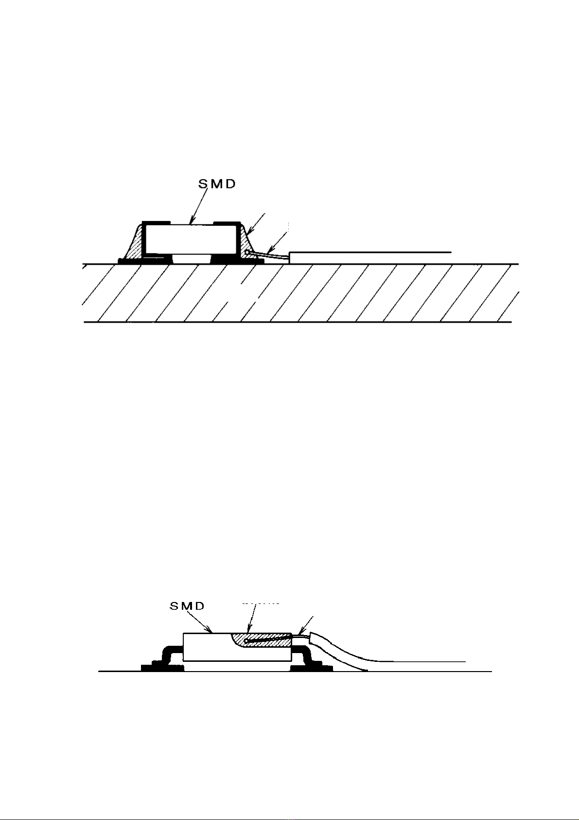
II-6 Thermocouple mounting examples
Example 1) Measuring solder temperature
(When checking whether the solder temperature is high enough to fully melt the solder on a side face
of a larger part where temperature is hard to rise, or when checking whether the solder temperature
and heating time are enough to oxidize the inner part of solder at an end portion of a board)
1. Fix the thermocouple tip measuring part with flux for stainless steel and high temperature solder.
If solder is hard to attach, lightly sand the thermocouple tip with sand paper.
Note: Do not pile up the high temperature solder and make a large mound. The solder profile must
be akin to the actual shape of the part as far as possible.
If solder is oxidized, or if the oxidant of flux cannot be taken off from the surface, remove the
solder once, and then try again soldering.
2. Lay the thermocouple wire close to the board surface as far as possible, and fix with heat-resistant
tape at a portion slightly apart from the tip in such a manner as to avoid application of stress.
Note: When fixing with high temperature solder, be sure to use a solder whose melting point is
higher than the reflow oven set temperature.
Example 2) Measuring the temperature of a part
(This is to check whether the heat-resistant temperature, time and temperature shock of a part are
within the allowable range.)
1. Fix the measuring part of thermocouple tip by thermosetting adhesive or inorganic adhesive.
Note: Pay attention not to alter the outer shape of the part largely by adhesive. To obtain accurate
measurement, file a part of thermocouple tip and embed it into the part.
High temperature solder
Thermocouple
Board
Thermocouple
Adhesive
Table of contents
Popular Test Equipment manuals by other brands

Reichert Technologies
Reichert Technologies Ametek Multi-Chek user guide

Adeunis RF
Adeunis RF FIELD TEST DEVICE - sigfox RC2 user guide

Meatest
Meatest M-142 Operation manuals

Oakton
Oakton CTSTestr 5 operating manual

Rigol
Rigol DS4000 Series Declassification guide

Tronic
Tronic Z30508 Operation and safety notes

Celltron Advantage
Celltron Advantage Midtronics CAD-5000 instruction manual

mensor
mensor PCS 400 Operation manual

Shimpo
Shimpo ST-329BL Operation manual

hager
hager EK087 manual

Precision Digital Corporation
Precision Digital Corporation PD9501 manual

Ocean Safety
Ocean Safety Jon Buoy mk4 operating instructions


