Malossi FORCE MASTER 2.1 User manual

5519529


20
ITALIANOENGLISH
20
ITALIANOENGLISH
FORCE MASTER 2.1
Assembly instructions
Control unit set-up
The control unit is equipped with 3
female connectors.
• Plug the cables into the relevant
connectors, which can be easily
identiied thanks to the colours.
CDI assembly
• Position the Force Master 2.1 CDI
under the seat (Fig. 1) and run the
wires to the engine, taking care that
they will not be damaged.

21
ITALIANOENGLISH
21
ITALIANOENGLISH
Injector
• Follow the wire coming out of the
injector and cut it at about 3 cm
from the connector, as shown in
Fig. 2.
• Connect the female faston 1
supplied into the kit to the original
connector 2by using the joint 3,
and carefully respecting the colours
of the wires (Fig. 3).
NB: pay attention to use the FEMALE
faston (1 - Fig. 3)!
• Close the joint using a pliers, such
as shown in Fig. 4.
• At this point connect the male
faston 4to the wiring of the vehicle,
using the joint as shown in Fig. 5.
Cables must be connected strictly
in accordance with the colours
shown in Fig. 3.
• Connect the control unit to the two
previously prepared connectors
(Fig. 6).
Ground
• Connect the black cable 5(negative
pole) coming out of the Malossi
control unit to the screw as shown
(Fig. 7).

22
ITALIANOENGLISH
22
ITALIANOENGLISH
TPS
• Identify the 5 cables TPS connector
located on the throttle body
(Fig. 8).
• On the yellow and black/grey
cables, apply the cable clamps
provided in the kit (Fig. 9).
• Make the following connections
using the cable clamp:
»Yellow Malossi control module
cable with yellow TPS cable
»Brown Malossi control module
cable with black/grey TPS cable
WARNING:
once the faston is connected to the
electrical tap connector we suggest
to tape the wire bunch, to avoid
electrical tap vibrations damaging
the wires.
Coil
• Locate the SMALL faston (orange
wire) connected to the original coil
and disconnect it.
• Insert the faston which comes from
the Malossi ECU (orange wire) to the
original coil.
• Connect the original wire to the
ECU’s bypass to complete the

23
ITALIANOENGLISH
23
ITALIANOENGLISH
circuit (Fig. 10).WARNING:
If you want to bring the vehicle
back to its original condition, you
must simply disconnect the cdi
connectors and reconnect the
Malossi connectors (Fig. 11).
Working
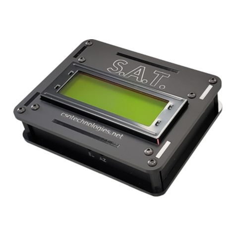
Control module status display
The control unit display shows the
status it is in, showing both the
functionality of the engine when
switched on and any possible errors
or supporting the user if the buttons
are pressed.
Buttons
The control unit is equipped with
3 buttons:
• “M” button: pallows to select the
dierent functions sequentially
• “-” e “+” buttons: only active in
certain operating modes, they allow

24
ITALIANOENGLISH
24
ITALIANOENGLISH
to increase or decrease the value
selected in the dierent functions
First power-up
Attention: when the key is turned
to start the vehicle, but the engine
is not started yet, the electronics
activates the power supply to all
actuators for a deined time of
approx. 3 seconds (“prime” phase).
The map and TPS calibration is
carried out starting with the vehicle
switched o.
TPS calibration
MIN adjustment
• Set the throttle knob to idle
• Press and hold the button (-) for the
entire calibration sequence
• Turn the key to ON
• The display shows lashing min
calibration logo
• If calibration successful, “OK”
appears
• If calibration was unsuccessful, the
message “OUT OF RANGE” appears
and it is necessary to repeat the
operation, checking that the
throttle is at idle

25
ITALIANOENGLISH
25
ITALIANOENGLISH
MAX adjustment
NB: You will need the help of a friend
to adjust the MAX.
• Set the gas knob to maximum
• Press and hold the button (+)
throughout the calibration
sequence
• Turn the key to ON
• The display shows the maximum
calibration logo lashing
• If calibration successful, “OK”
appears
• If calibration was unsuccessful, the
message “OUT OF RANGE” appears
and it is necessary to repeat the
operation, checking that the
throttle is at idle
MAP selection
• Press and hold button M throughout
the calibration sequence
• Turn the key ON : the display will
show the selected map
• To change the map, turn the key
OFF-ON (keeping the M button
pressed), until the desired map is
selected
NB: the control unit will only display
the pre-set maps
The vehicle can now be switched on
and used.

26
ITALIANOENGLISH
26
ITALIANOENGLISH
Working (Fig. 12)
These adjustments can be carried
out with the engine running, in
ventilated places.
Each time the ‘M’ button is pressed,
the display shows an indication
of the function being activated,
together with the switching on of a
dedicated LED on the edge of the
display.
In selection sequence, the
modes are:
1. “Low”: : shows the active
correction at low RPM (< 3000
RPM). If the engine is on, after
a few seconds of inactivity
it returns to the engine
screen display.
The “-” and “+” buttons reduce or
increase the injection correction
in 2% steps in the relevant RPM
ranges. When these buttons are
pressed, the selected correction
lashes. To conirm the selected
correction, it is necessary to wait
for the end of the lashing.
2. “Mid”: shows the active
correction at medium RPM
(between 3000 and 6000 RPM).
If the engine is on, after a few
seconds of inactivity it returns to
the engine screen display.

27
ITALIANOENGLISH
27
ITALIANOENGLISH
The “-” and “+” buttons reduce or
increase the injection correction
in 2% steps in the relevant RPM
ranges. When these buttons are
pressed, the selected correction
lashes. To conirm the selected
correction, it is necessary to wait
for the end of the lashing.
3. “High”: shows the active
correction at high RPM (> 6000
RPM). If the engine is switched
on, after a few seconds of
inactivity it returns to the engine
screen display.
The “-” and “+” buttons reduce or
increase the injection correction
in 2% steps in the relevant speed
range. When these buttons are
pressed, the selected correction
lashes. To conirm the selected
correction, it is necessary to wait
for the end of the lashing.
4. “Maps”: the active map is
displayed with the word “M”
followed by the map number and
a dierent map can be selected
using the “-” and “+” buttons. If
the engine is switched o, the
active map is always displayed. If
the engine is switched on, after
a few seconds of inactivity the
engine screen display returns.
Pressing the “-” and “+” buttons
shows the active map number on

28
ITALIANOENGLISH
28
ITALIANOENGLISH
the right-hand side of the display,
while showing the map about to
be activated in lashing mode on
the left. To activate the map, wait
for the end of the lashing and
the letter “M” on the left followed
by the map number that has
been activated on the right.
5. “Thr”: shows “T %” for a few
seconds, then the TPS opening
percentage is displayed. By
moving the throttle all the way,
the percentage displayed should
range from 0% to 100%. If the
stroke does not go from 0 to
100, TPS calibration must be
performed. The TPS value always
remains displayed regardless of
the engine state.
6. “Diag”: shows the letter “D” for
a few seconds, then the active
errors if present, otherwise it
shows “NO ERROR”. If the engine
is switched on, after displaying
the complete sequence of all
information, it returns the engine
screen display returns, otherwise
this information continues to run
on the display.
7. “Info”: displays the letter “I” for
a few seconds, then the ECU
mapping name and software
version are shown. If the engine
is running, after displaying both

29
ITALIANOENGLISH
29
ITALIANOENGLISH
information, the engine screen
display returns, otherwise this
information continues to scroll
across the display.
Diag
The Force Master 2.1 control unit is
equipped with a display that shows
possible diagnostic messages:
• “KO MAP” Calibration Error
There is an invalid calibration.
The control unit does not allow the
vehicle to start.
The calibration must be
reprogrammed, an operation only
possible at Malossi.

30
ITALIANOENGLISH
30
ITALIANOENGLISH
• “TUNING TPS” - TIncorrect
throttle calibration (for vehicles
where TPS calibration is required)
The throttle calibration procedure
was not carried out correctly by the
user and must be repeated.
The ECU may be behaving sub-
optimally, with the injection too
lean or too rich.
• “INJ1 S.C.” - Short-circuited
injector to battery positive
The connection to the wiring
harness has not been made
correctly and the injection output is
shorted to the battery.
The control unit goes into
protection mode and injection is
not implemented.
The control unit must be switched
o and on again to allow the vehicle
to start. If the error persists, it is
essential for the operator to check
the injection connections.
• “INJ1 O.C.” - Injector not
connected
MThe connection to the injector
is missing.
The engine cannot be started.
If the error persists, the
operator must check the
injection connections.

31
ITALIANOENGLISH
31
ITALIANOENGLISH
• “IGN LOST” - No coil connected
The connection to the coil
is missing.
The control unit may be restricted
in injection and is not injecting after
the original system’s limiter.
If the error persists, it is imperative
for the operator to check the
connection to the coil.
• “TPS N.C.” - Throttle connector
not connected (for vehicles where
TPS calibration is required)
The connection to the throttle cable
is missing.
The control unit may be behaving
sub-optimally, with the injection too
lean or too rich.
If the error persists, it is imperative
for the operator to check the
connection to the throttle cable.
• “TPS KWP2000” - OBD
connector for throttle check not
connected (for vehicles with
diagnostic connector)
The throttle reading via the OBD
connector is not correct.
The ECU may be behaving sub-
optimally, with the injection too
lean or too rich.
The operator must check the
connection to the OBD connector.

32
ITALIANOENGLISH
32
ITALIANOENGLISH
• “VBATT LOW” - Battery voltage
too low
The battery voltage has been below
11V for at least 10 seconds.
The control unit is behaving
normally but problems may arise in
the general operation.
The operator must make
appropriate checks on the system
because this problem cannot be
caused by the control unit.
• “VBATT HIGH” - Battery voltage
too high
The battery voltage has been above
15.5V for at least 5 seconds.
The control unit is behaving
normally but problems may arise in
the general operation.
The operator must make
appropriate checks on the system
because this problem cannot be
caused by the control unit.
Normal operation
When switched on, the control unit
display shows the status of
• Selected map
• Low/mid/high setting
After this, the RPM and THR status
bars remain active.

33
ITALIANOENGLISH
33
ITALIANOENGLISH
If errors are present, the Diag LED
will lash. It will then be necessary to
interrogate the control unit by going
to the speciic function to ind out
the error.
Technical details
• Carburation adjusting
• ± 14% al LOW / HIGH / MID
• RPM limiter : +1,800 RPM
• 4 dierent maps
• Temperature range = -30°C +80°C
• Minimum operating voltage = +7V
• Maximum operating voltage = +16V
• Average current consumption
<-200mA
• Environmental protection = IP65
Maps
The Force Master 2.1 CDI is
programmed with 4 base fuel curves:
• curve 0: original exhaust system,
Malossi cylinder kit, original
camshaft and original ilter;
• curve 1: Malossi with DB killer
exhaust system, Malossi cylinder kit,
original camshaft and Malossi ilter.
• curve 2: Malossi with DB killer
exhaust system, Malossi cylinder kit,
Malossi camshaft and original ilter.
• curve 3: Malossi with DB killer
exhaust system, Malossi cylinder kit,

34
ITALIANOENGLISH
34
ITALIANOENGLISH
Malossi camshaft and Malossi ilter.

35
ITALIANOENGLISH
35
ITALIANOENGLISH
We hope you found the above
instructions suiciently clear.
However, if any points are not
particularly clear, please contact
us completing the special form
inserted in the “contact” section on
our Internet site (malossistore.com).
We thank you in advance for any
comments and suggestions you may
wish to send us. So goodbye from us
all at Malossi, and please accept our
compliments. Have Fun. GOOD LUCK
and … see you next time.
The descriptions in this publication
are not binding. Malossi reserves
the right to make modiications, if
it considers them necessary, and
does not accept any responsibility
for any typographic or printing
errors. This publication replaces all
previous publications referring to the
updating matters contained therein.
WARRANTY
Look up warranty terms in our
website malossistore.com.

36
ITALIANOENGLISH
36
ITALIANOENGLISH
These products are reserved solely
for races in locations reserved for
those purposes and in accordance
with the regulations issued by the
competent authorities for sports
events. We decline any and all
responsibility for improper use.

37
Fig. 1
Other manuals for FORCE MASTER 2.1
3
This manual suits for next models
1
Table of contents
Other Malossi Controllers manuals

