Malta Dynamics A6101 User manual

Beam Trolley
Instruction Manual A6101

Beam Trolley User Instruction Manual
MaltaDynamics.com | 800-494-1840
2
Manual Revision Code:
MARCH 30,2021
Beam Trolley
INSTRUCTION MANUAL
These instructions apply to the following model(s):
A6101
Manual Revision:
MARCH 30, 2021
A copy of this manual must be available to users at all times. Visit www.MaltaDynamics.com
for the latest user instruction manual based upon date of manufacture.

3
Beam Trolley Instruction Manual
MaltaDynamics.com | 800-494-1840
Visit www.MaltaDynamics.com for the latest user
instruction manual based upon date of manufacture.
TABLE OF CONTENTS
Under Penalty of Law ------------------------------------------------- 4
Materials and Construction ------------------------------------------- 4
Purpose ----------------------------------------------------------------- 4
Instructions for Use ---------------------------------------------------- 5
Limitations for Use ----------------------------------------------------- 6
Connector Compatibility Limitations --------------------------------- 7
Instructions ------------------------------------------------------------ 9
Product Labels -------------------------------------------------------------- 13
Training --------------------------------------------------------------------- 14
Inspection ----------------------------------------------------------------- 14
Maintenance and Cleaning ------------------------------------------- 15
Inspection Log --------------------------------------------------------- 16
Warranty ---------------------------------------------------------------- 17
WARNING: ALL PERSONS USING THIS EQUIPMENT MUST
READ AND UNDERSTAND ALL INSTRUCTIONS. FAILURE TO DO
SO MAY RESULT IN SERIOUS INJURY OR DEATH. USERS SHOULD
BE FAMILIAR WITH PERTINENT REGULATIONS GOVERNING THIS
EQUIPMENT. ALL INDIVIDUALS WHO USE THIS PRODUCT MUST
BE PROPERLY INSTRUCTED ON HOW TO USE THE DEVICE. AVOID
CONTACT WITH PHYSICAL HAZARDS (THERMAL, CHEMICAL,
ELECTRICAL, ETC.). MAKE ONLY COMPATIBLE CONNECTIONS.

Easy Slider I-Beam Anchor User Instruction
Manual MaltaDynamics.com | 800-494-1840
4
Manual Revision Code:
MARCH 30,2021
UNDER PENALTY OF LAW
This manual must be read and understood in its entirety, and used as part of a
fall protection training program, as required by OSHA or any state/local regulatory
agencies. This instruction manual is intended to meet industry standards required
by ANSI Z359.18-2017 and should be used as part of an Employee Fall Safety
Training Program as required by OSHA. User must read and fully understand the
limitations and proper use of equipment. All users must be properly trained by
their employer prior to use, per OSHA 29 CFR 1910.66, 29 CFR 1926.503, and
applicable local standards.
NOTE: This User Instruction Manual is not to be removed except by the equipment
user. Current User Instruction Manuals must always be available to the user. Read
and understand these instructions before using equipment. Do not discard these
instructions.
Misuse or failure to follow warnings, instructions, and limitations
on the use of this equipment may result in serious personal
injury or death. For further instructions about proper use, refer
to a supervisor or contact Malta Dynamics at 1-800-494-1840.
MATERIALS AND CONSTRUCTION
• Hardware: Plated alloy steel, 5000 lbs. minimum breaking
strength and Aluminum alloy.
PURPOSE
The A6101 is an anchorage connector designed to function as an interface
between the anchorage and a fall protection, work positioning, rope access, or
rescue system for the purpose of coupling the system to the anchorage. Any
references to “anchorage connector” in this manual include, and apply to, the
A6101.

5
Beam Trolley Instruction Manual
MaltaDynamics.com | 800-494-1840
Visit www.MaltaDynamics.com for the latest user
instruction manual based upon date of manufacture.
INSTRUCTIONS FOR USE
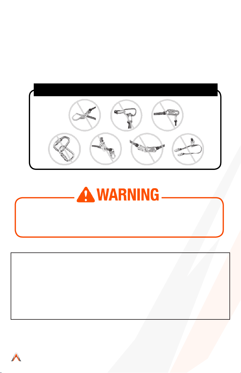
Do not alter or intentionally misuse this equipment.
Read This Instruction Manual Carefully Before Using
This Equipment.
1. A user must be of sound mind and body to properly and safely use this
equipment in normal and emergency situations. Users must have a
physician ensure they are clear of any medical conditions that may affect
the proper and safe use of this equipment in normal and emergency
situations.
2. Before using a personal fall arrest system, user must be trained in
accordance with the requirements of OSHA 29 CFR 1910.66 in the safe
use of the system and its components.
3. Use only with ANSI/OSHA compliant personal fall arrest or restraint
systems. The anchorage must have the strength capable of supporting a
static load, applied in the directions permitted by the system, of at least
5,000-lbf (22kN) in the absence of certification.
4. The user shall be equipped with a means of limiting the maximum
dynamic forces exerted on the user during the arrest of a fall to a
maximum of 8 kN (1800-lbf). In the EU these forces must be limited to 6
kN (1350-lbf).
5. Use of this product must be approved by an engineer or other qualified
person to be compatible with any and all structural & operational
characteristics of the selected installation location and system to be
connected to this anchorage connector.
6. The anchorage connector must be inspected prior to each use for wear,
damage, and other deterioration. If defective components are found the
anchorage connector must be immediately removed from service in
accordance with the requirements of OSHA 29 CFR 1910.66 and
1926.502.
7. The anchorage connector should be positioned in such a way that
minimizes the potential for falls and the potential fall distance during use.
The complete fall protection system must be planned (including all
components, calculating fall clearance, and swing fall) before using.
8. A rescue plan, and the means at hand to implement it, must be in place
that provides the prompt rescue of users in the event of a fall, or assures
that users are able to rescue themselves.
9. After a fall occurs the anchorage connector must be removed from service
and destroyed immediately.

Easy Slider I-Beam Anchor User Instruction
Manual MaltaDynamics.com | 800-494-1840
6
Manual Revision Code:
MARCH 30,2021
LIMITATIONS FOR USE
Do not use this equipment if you are unable to tolerate the impact of a
fall arrest. Age and tness can seriously affect your ability to withstand
a fall. Consult with a physician if in doubt. Minors, pregnant women,
and anyone with a history of back and/or neck problems must not use
this equipment.
1. The anchorage connector is designed for single user, with a capacity up
to 310 lbs (140 kg) including
clothing, tools, etc.
2. The anchorage connector may only be loaded as shown in the
LOADING CONDITIONS DIAGRAM.
3. The anchorage connector is designed to be used in temperatures
ranging from -40ºF to +130ºF (-40°C to +54°C).
4. Do not expose the anchorage connector to chemicals or harsh solutions
which may have a harmful effect.
5. Do not alter or modify this product in anyway.
6. Caution must be taken when using any component of a fall protection,
work positioning, rope access, or rescue system near moving
machinery, electrical hazards, sharp edges, or abrasive surfaces, as
contact may cause equipment failure, personal injury, or death.
7. Do not use/install equipment without proper training by a “competent
person” as defined by OSHA 29
CFR 1926.32(f).
8. Do not remove the labeling from this product.
9. Additional requirements and limitations may apply depending on
anchorage type and fastening option utilized for installation. All
placements must be approved by an engineer or other qualified person.
10. This anchorage connector should not be used as part of a horizontal
lifeline system that has not been designed and or approved to be used
with 5,000-lbf anchorage connectors.
11. The anchorage connetor should only be used for personal fall protection
and not for lifting equipment.
The anchorage connector shall not be used outside its limitations, or
for any purpose other than that for which it is intended.

7
Beam Trolley Instruction Manual
MaltaDynamics.com | 800-494-1840
Visit www.MaltaDynamics.com for the latest user
instruction manual based upon date of manufacture.
CONNECTOR COMPATIBILITY LIMITATIONS
Malta Dynamics equipment must be coupled only to compatible connectors that
are suitable to your application. Ensure all connections are compatible in size,
shape and strength. Ensure all connectors are fully closed and locked. OSHA 29
CFR 1926.502 prohibits the use of snap hooks to engage to objects unless the
following requirements are met:
•Direct connection of a snaphook to horizontal lifeline.
•Two (or more) snaphooks connected to one D-ring.
•Two snaphooks connected to each other.
•A snaphook connected back on its integral lanyard.
•A snaphook connected to a webbing loop or webbing lanyard.
•Improper dimensions of the D-ring, rebar, or other connection point in
relation to the snaphook dimensions that would allow the snaphook
keeper to be depressed by a turning motion of the snaphook.
Use of a non-locking snap hook can result in rollout (a process by which a snap
hook or carabiner unintentionally disengages from another connector or the
object to which it is coupled (ANSI Z359.0- 2012). Malta Dynamics connectors
(snap hooks and carabiners) are designed to be used only as specied in each
product’s user’s instructions.
Avoid the following types of connections:
• Two or more snap hooks or carabiners attached to one D-Ring.
• A snap hook connected to its integral lanyard.
• A snap hook connected to a horizontal lifeline.
•Connection in a manner that results in a load on the gate. NOTE: Large throat
opening snap hooks should not be connected to standard size D-Rings or
similar objects. This could result in a load on the gate if the hook or D-Ring
twists or rotates. Large throat snap hooks are designed for use on structural
elements such as rebar or cross members that are not shaped to capture the
gate of the hook.
•False engagement connections, where protruding features of the snap hook
or carabiner may catch on the anchor and seem fully engaged to the anchor
point. Always conrm engagement.
• Connection to snap hooks or carabiners.
•Direct connection to webbing lanyard, webbing loop, rope lanyard or tie-back

Easy Slider I-Beam Anchor User Instruction
Manual MaltaDynamics.com | 800-494-1840
8
Manual Revision Code:
MARCH 30,2021
Use caution when employing this equipment around machines,
electrical hazards, chemical hazards and sharp edges or abrasive
surfaces, as contact may cause equipment failure, personal injury, or
death.
PERFORMANCE:
Static tensile strength: 5000-lbf (22kN)
minimum
Maximum capacity: One worker with max
weight of 310-lbs.
Weight: 9.27-lbs
Beam flange width range: 3”-10”
Beam flange thickness: 1/4“- 7/8”
(unless the manufacturer’s instructions for both the lanyard and connector
specically allow such a connection).
•A snap hook connected to a D-Ring, Rebar, or other connection point with
improper dimensions/congurations could cause the snap hook keeper to
become depressed by the turning motion of the snap hook; the snap hook or
carabiner may not fully close and lock or roll-out may occur.
Illustration 2 depicts examples of inappropriate connections:
Illustration 2: Inappropriate Connections
REGULATORY COMPLIANCE: ANSI
Z359.17-2017, OSHA 1926.502, OSHA 1910.66,
COMPONENT MATERIALS:
Aluminum: Cross Bar, Rollers
Polyester: Webbing
Zinc Plated Steel: Swivel
Stainless Steel: Spring, Hardware

9
Beam Trolley Instruction Manual
MaltaDynamics.com | 800-494-1840
Visit www.MaltaDynamics.com for the latest user
instruction manual based upon date of manufacture.
INSTRUCTIONS:
(Rollers) (Rollers)
(Notches) (Notches)
(Toggle Plate)
(Secondary Safety Lock)
(Toggle Plate)
(Secondary Safety Lock)
(5,000-lbf Swivel)
1. Locate a structural steel beam flange capable of withstanding a 5,000-
lbf (22kN). static load or meeting OSHA 1926.502 requirements for a
safety factor of two. Mounting location must be approved by an
engineer or qualified person.
2. Push up on the toggle plate to allow the adjustable rollers to move.
3. Keeping the unit perpendicular to the beam, fit the rollers over the edges
of the beam flange.

Beam Trolley User Instruction Manual
MaltaDynamics.com | 800-494-1840
10
4. Slide the adjustable rollers so that both sets of rollers are fully resting
on the beam flange.
5. Release the toggle plate and pull back on the adjustable rollers to
ensure the ratchet teeth are fully seated in the nearest ratchet
notches.
6. Tug, rock, and twist the anchorage connector in all directions to
ensure that it can not come off of the flange.
7. Screw tight the secondary safety locking screws on the bottom of the
toggle plate to ensure the rollers can not move off the edge of the
flange.
8. The rollers must ride on a clear, clean surface. Remove any dirt and
grit if necessary.
9. Ensure that Beam Trolley can not slide off end of beam it is
attached to. Install stoppers if necessary.
*Always re-adjust according to Installation steps 1-9 when moving to a
new or different sized beam.
*Remove any dirt
and grit if
necessary.
*Weld or bolt in
stoppers if necessary
to ensure that Beam
Trolley can not slide
off the end.
Manual Revision Code:
MARCH 30,2021

11
Easy Slider I-Beam Anchor Instruction Manual
MaltaDynamics.com | 800-494-1840
Visit www.MaltaDynamics.com for the latest user
instruction manual based upon date of manufacture.
LOADING CONDITIONS DIAGRAM
Placement at or below a user’s working height requires integration of a
compatible ANSI Z359.1 shock-absorbing lanyard that does not allow the user to
extend more than 6 feet (in any direction) from the anchorage connector before
the shock absorber is activated. The beam anchor must be attached to the I-
beam flange facing the user (top flange if above, bottom flange if below, etc.).
ACCEPTABLE LOADING
30° MAX 30° MAX
LOADING CONDITIONS DIAGRAM

Easy Slider I-Beam Anchor User Instruction
Manual MaltaDynamics.com | 800-494-1840
12
Manual Revision Code:
MARCH 30,2021
*All products subjected to fall
arresting forces should be removed
from service immediately!
DECK/FLOOR/GROUND LEVEL
WORK SURFACE
WORK
SURFACE
(ANCHOR POINT)
MINIMUM CLEARANCE 3ft
(1m)
*The user shall be equipped with a means of
limiting the maximum dynamic forces
exerted on the user during the arrest of a fall
to a maximum of 8 kN (1800-lbf). In the EU
these forces must be limited to 6 kN (1350-
lbf).
WARNING!!! SWING FALLS MAY OCCUR WHEN THE WORKER IS NOT DIRECTLY UNDER ANCHOR
POINT.

13
Easy Slider I-Beam Anchor Instruction Manual
MaltaDynamics.com | 800-494-1840
Visit www.MaltaDynamics.com for the latest user
instruction manual based upon date of manufacture.
PRODUCT LABELS
The following labels are affixed to the product and must not be removed:
WARNING LABEL
WARNING: It is essential to the safety of the end user that the seller of this device
include all instructions pertaining to the proper use, maintenance and inspection of the
device in the language of the country in which the product is to be sold.
BEAM TROLLEY
Model:
5,000-lbf (22kN) UTS
Aluminum, Zinc Plated Steel,
Stainless Steel
MAX
A6101
(1) person 310-lbs (140kg)
Batch # BTA-XXX

Easy Slider I-Beam Anchor User Instruction
Manual MaltaDynamics.com | 800-494-1840
14
Manual Revision Code:
MARCH 30,2021
TRAINING
Employers must provide training to any employee who may be exposed to fall
hazards in order to enable the employee to recognize and reduce fall hazards.
Training must be conducted by a Competent or Qualied Person. Trainer and
trainees must not be exposed to fall hazards during the training course. This
equipment is intended to be used by persons trained in its correct application
and use.
INSPECTION
Official periodic inspection must be made at least annually. The inspection must
be performed by a qualified person other than the intended user. If severe
weather or conditions exist then inspections must be carried out more frequently.
All inspection results must be logged in the space provided above. (It is
recommended that the anchor device is marked with the date of the next or last
inspection.)
1. Make sure all labeling is affixed to the unit.
2. Inspect anchoring system for signs of damage or wear.
3. Make sure the ring is free to swivel and pivot.
4. Check for excessive play and wear on the retaining bushing (Bushing
should not wiggle or rotate.)
5. Ensure latches engage and disengage properly.
6. Record inspection results in the space provided above.
Note: Keep all instructions available for reference. Record the date of first use:
Record all observations and results of each inspection in your Hog Tracker account
or inspection log. If inspection reveals any defect, inadequate maintenance, or
unsafe condition, remove Anchor from service immediately. Any equipment that
has been subjected to the forces of arresting a fall must be removed from
service immediately.
Note: Equipment must not be altered in any way, including attempted repair.
Only manufacturer, or entities authorized in writing by the manufacturer, may
make repairs to this product. If inspection reveals any defective condition,
remove from service immediately.

15
Easy Slider I-Beam Anchor Instruction Manual
MaltaDynamics.com | 800-494-1840
Visit www.MaltaDynamics.com for the latest user
instruction manual based upon date of manufacture.
MAINTENANCE & CLEANING
Wipe off all surface dirt. Clean with compressed air and/or a stiff brush using
plain water or a mild soap and water solution to clean away contaminants; wipe
hardware dry with a clean cloth. Hang away from heat and allow to dry
completely. Store in dry, clean environment away from direct sunlight and
excessive heat. Avoid storage in areas where chemical vapors may exist.
Thoroughly inspect lanyard after extended storage.
Frequency:
• All equipment must be visually inspected prior to each use according to the
manufacturer’s instructions included at time of shipment. Inspections must be
performed by a Competent Person other than the user (as defined by OSHA) a
minimum of once per year.
• Record the results of each formal inspection in your Hog Tracker account or
inspection log.
•
•
NOTE: Per Cal/OSHA PFAS must be inspected by a competent person at least
once a year, in accordance with the manufacturer’s recommendations, with
inspection dates documented.
Repairs to the Easy Slider I-Beam anchor can only be made by a Malta
Dynamics Fall Protection representative or an entity authorized by Malta
Dynamics. Contact us for all maintenance and repair needs or to inquire about
a return at: 1-800-494-1840.
Harsh weather and harsh environments, prolonged use, and
other extreme working conditions may require you to have this
inspected by a competent or qualified person than yourself at
least once a year.

Easy Slider I-Beam Anchor User Instruction
Manual MaltaDynamics.com | 800-494-1840
16
Manual Revision Code:
MARCH 30,2021
INSPECTION LOG
Date of Manufacture: __________________________________________________
Model Name/Number: _________________________________________________
Serial: ________________________________________________________________
Date of First Use: _____________________________________________________
Inspection Date Items Noted Corrective Action Approved By

17
Easy Slider I-Beam Anchor Instruction Manual
MaltaDynamics.com | 800-494-1840
Visit www.MaltaDynamics.com for the latest user
instruction manual based upon date of manufacture.
WARRANTY
THE FOLLOWING IS MADE IN LIEU OF ALL WARRANTIES OR CONDITIONS,
EXPRESS OR IMPLIED, INCLUDING THE IMPLIED WARRANTIES OR
CONDITIONS OF MERCHANTABILITY OR FITNESS FOR A PARTICULAR
PURPOSE. Equipment offered by Malta Dynamics is warranted against factory
defects in workmanship and materials for a period of one year from date of
installation or rst use by the original owner. LIMITED REMEDY: Upon notice
in writing, Malta Dynamics will repair or replace all defective items at Malta
Dynamics’s sole discretion. Malta Dynamics reserves the right to require that
the defective item be returned to its plant for inspection before determining
the appropriate course of action. Warranty does not cover equipment damage
resulting from wear, abuse, damage in transit, failure to maintain the product
or other damage beyond the control of Malta Dynamics. Malta Dynamics shall
be the sole judge of product condition and warranty options. This warranty
applies only to original purchaser and is the only warranty applicable to this
product. Please contact Malta Dynamics customer service department at
800-494-1840 for assistance. LIMITATION OF LIABILITY: IN NO EVENT WILL
MALTA DYNAMICS BE LIABLE FOR ANY INDIRECT, INCIDENTAL, SPECIAL OR
CONSEQUENTIAL DAMAGES INCLUDING, BUT NOT LIMITED TO LOSS OF
PROFITS, IN ANY WAY RELATED TO THE PRODUCTS REGARDLESS OF THE
LEGAL THEORY ASSERTED.
Table of contents