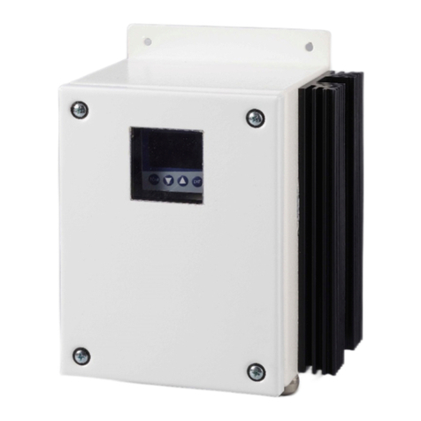
M&C 70304 User manual

Electronic Temperature Controller
70304, 70304.2
Instruction Manual
Version 1.02.00

2 Temperature controller 70304 | 1.02.00 www.mc-techgroup.com
Dear customer,
Thank you for buying our product. In this instruction manual you will find all necessary information about this M&C
product. The information in the instruction manual is fast and easy to find, so you can start using your M&C product
right after you have read the manual.
If you have any question regarding the product or the application, please don’t hesitate to contact M&C or your
M&C authorized distributor. You will find all the addresses in the appendix of this manual.
For additional information about our products and our company, please go to M&C’s website www.mc-
techgroup.com. There you will find the data sheets and manuals of our products in German and English.
This Operating Manual does not claim completeness and may be subject to
technical modifications.
©
07/2023 M&C TechGroup
Germany GmbH. Reproduction of this document or
its content is not allowed without permission from
M&C.
With the release of this version all older manual versions will no longer be valid.
The German instruction manual is the original instruction manual. In case of ar-
bitration only the German wording shall be valid and binding.
Version: 1.0
2.00

www.mc-techgroup.com Temperature controller 70304 | 1.02.00 3
List of content
1General information.............................................................................................................................................4
2Declaration of conformity ...................................................................................................................................4
3Safety instructions................................................................................................................................................5
4Warranty.................................................................................................................................................................5
5Used terms and signal indications.....................................................................................................................6
6Introduction...........................................................................................................................................................7
7Receipt of goods and storage.............................................................................................................................7
8Description.............................................................................................................................................................8
9Dimensions and installation ...............................................................................................................................9
10 Technical Data.................................................................................................................................................11
11 Electrical connection......................................................................................................................................11
11.1 Replacing controller 703 by controller 70304.................................................................................................................................12
12 Operating principle ........................................................................................................................................13
12.1 Parameter of the user level with factory setting............................................................................................................................13
13 Change of parameters ...................................................................................................................................14
13.1 Removing and activating the level inhibit ........................................................................................................................................14
13.2 Menu structure...................................................................................................................................................................................................15
13.3 Time Out.................................................................................................................................................................................................................16
14 Change of the setpoint ..................................................................................................................................16
15 Comissioning...................................................................................................................................................16
15.1 Entry and check of controller parameters .........................................................................................................................................16
15.2 Self-optimising (PID action) of control circuit .................................................................................................................................17
15.3 Commissioning with heated foreign components .....................................................................................................................17
16 Low temperature alarm and excess temperature limitation...................................................................18
16.1 Restarting after excess or low temperature alarm........................................................................................................................18
17 70304 or 70304.2 with mA-output...............................................................................................................18
17.1 Adjusting Signal type and temperature range...............................................................................................................................19
18 Decommissioning...........................................................................................................................................19
19 Maintenance....................................................................................................................................................19
20 Proper disposal of the device .......................................................................................................................20
21 Spare part list ..................................................................................................................................................20
22 Appendix..........................................................................................................................................................20
List of Illustrations
Figure 1 Display/control elements.........................................................................................................................................................................8
Figure 2 Mounting cutout for controller 70304 for front panel mounting...................................................................................9
Figure 3 Housing and mounting dimensions for controller 70304 for front panel mounting.........................................9
Figure 4 Housing and mounting dimensions for controller 70304.2 for rail mounting .................................................... 10
Figure 5 Menu structure............................................................................................................................................................................................ 15

4 Temperature controller 70304 | 1.02.00 www.mc-techgroup.com
Head Office
M&C TechGroup Germany GmbH Rehhecke 79 40885 Ratingen Germany
Telephone: 02102 / 935 - 0
Fax: 02102 / 935 - 111
E - mail: info@mc-techgroup.com
www.mc-techgroup.com
1GENERAL INFORMATION
The product described in this manual has been built and tested in our production facility.
All M&C products are packed to be shipped safely. To ensure the safe operation and to maintain the safe condition,
all instructions and regulations stated in this manual need to be followed. This manual includes all information
regarding proper transportation, storage, installation, operation and maintenance of this product by qualified per-
sonnel.
Please follow all instructions and warnings closely.
Please read this manual carefully before commissioning and operating the device. If you have any questions re-
garding the product or the application, please don’t hesitate to contact M&C or your M&C authorized distributor.
2DECLARATION OF CONFORMITY
CE - Certification
The product described in this operating manual complies with the following EU directives:
EMV-Instruction
The requirements of the EU directive 2014/30/EU “Electromagnetic compatibility“ are met.
Low Voltage Directive
The requirement of the EU directive 2014/35/EU “Low Voltage Directive“ are met.
The compliance with this EU directive has been examined according to DIN EN 61010.
Declaration of conformity
The EU Declaration of conformity can be downloaded from the M&Chomepage or directly requested from M&C.

www.mc-techgroup.com Temperature controller 70304 | 1.02.00 5
3SAFETY INSTRUCTIONS
Please take care of the following basic safety procedures when mounting, starting up or operating this
equipment:
Read this operating manual before starting up and use of the equipment. The information and warnings given in
this operating manual must be heeded.
Any work on electrical equipment is only to be carried out by trained specialists as per the regulations currently in
force.
Attention must be paid to the requirements of VDE 0100 (IEC 364) when setting high-power electrical units with
nominal voltages of up to 1000 V, together with the associated standards and stipulations.
Check the details on the type plate to ensure that the equipment is connected to the correct mains voltage.
Protection against touching dangerously high electrical voltages:
Before opening the equipment, it must be switched off and hold no voltages. This also applies to any external
control circuits that are connected.
The device is only to be used within the permitted range of temperatures and pressures.
Check that the location is weather-protected. It should not be subject to either direct rain or moisture.
The temperature controllers 70304 and 70304.2 must not be used in hazardous areas.
Installation, maintenance, monitoring and any repairs may only be done by authorized personnel with respect to
the relevant stipulations.
4WARRANTY
If the equipment fails, please contact M&C directly or else go through your M&C authorised dealer.
We offer a one year warranty as of the day of delivery as per our normal terms and conditions of sale, and assuming
technically correct operation of the unit. Consumables are hereby excluded. The terms of the warranty cover repair
at the factory at no cost or the replacement at no cost of the equipment free ex user location. Reshipments must
be send in a sufficient and proper protective packaging.

6 Temperature controller 70304 | 1.02.00 www.mc-techgroup.com
5USED TERMS AND SIGNAL INDICATIONS
Danger
This means that death, severe physical injuries and/or important material
damage will occur in case the respective safety measures are not fulfilled.
Warning
This means that death, severe physical injuries and/or important material
damage may occur in case the respective safety measures are not fulfilled.
Caution
This means that minor physical injuries may occur in case the respective
safety measures are not fulfilled.
Caution
Without the warning triangle means that a material damage may occur in
case the respective safety measures are not met.
Note
These are important information about the product or parts of the operating
manual which require user’s attention.
Qualified Personnel
These are persons with necessary qualification who are familiar with installa-
tion, use and maintenance of the product.
High voltages!
Protect yourself and others against damage which might be caused by high
voltages.

www.mc-techgroup.com Temperature controller 70304 | 1.02.00 7
6INTRODUCTION
The compact microprocessor contolled temperature controllers type 70304 and 70304.2 are mainly used for M&C
components that have no temperature controller in their standard specification. If the temperature controller is
ordered together with an M&C component, he already is parameterized and preprogrammed. Additionally to the
controllers in dependance on the M&C device a relais with sufficient switching capacity is necessary.
The controllers have an adjustable sensor input for all common temperature sensors and they can be used as an
programmable two or three step or continious and self-optimizing controller with PID structure.
7RECEIPT OF GOODS AND STORAGE
The temperature controllers 70304 and 70304.2 are complete pre-installed units.
•Please take the temperature controller and possible special accessories carefully out of the packaging material
immediately after arrival, and compare the goods with the items listed on the delivery note!
•Check the goods for any damage caused during delivery and, if necessary, notify your transport insurance com-
pany without delay of any damage discovered!
Note
The equipment should be stored in a protected, frost-free room!

8 Temperature controller 70304 | 1.02.00 www.mc-techgroup.com
8DESCRIPTION
The controller type 70304 is provided for front panel mounting and the controller type 70304.2 is provided for
rail mounting.
(1) Actual value display
red, 10mm high, 4 digits
(4) PGM-key in order to select parameters
in order to change values
Exit-key in order to leave the levels
(2) Active Setpoint
Factory setting SP1
(5)
Indication
yellow for
- Switch status of binaryoutputs 1 – 6
(display lights up = on)
- ramp/programm function is active
- manual operation is active
(3) Setpoint
Four digit, green; decimal place is configurable;
Also used for operator prompting (display of pa-
rameter and level symbols)
(6)
16-segment display for the unit °C / °F
factory setting °C
Figure 1 Display/control elements

www.mc-techgroup.com Temperature controller 70304 | 1.02.00 9
9DIMENSIONS AND INSTALLATION
45
+0,6
0
45
+0,6
0
Figure 2 Mounting cutout for controller 70304 for front panel mounting
Figure 3 Housing and mounting dimensions for controller 70304 for front panel mounting
PGM EXIT
48
51
90
105
44,5
48

10 Temperature controller 70304 | 1.02.00 www.mc-techgroup.com
PGM
EXIT
1/7
1/6
N 3/2
L 3/1
3/5
3/4
3/8
3/7
2/8
2/6
2/4
2/3
2/2
110
122
55
37,5
5,75
4,5
61,25
75
Figure 4 Housing and mounting dimensions for controller 70304.2 for rail mounting

www.mc-techgroup.com Temperature controller 70304 | 1.02.00 11
10 TECHNICAL DATA
Temperatue controller
type
70304
70304.2
Part No.
01B8401
01B8456
Temperature sensor
Resistance thermometer, thermocouple
Logic output
0/12 V DC, max. 30 mA to an external solid state relay
Switching capacity solid state relais
external
Control mode
PID
Status alarm
High temperature limiter with continious cutoff, low temperature alarm: 1 contact
NO each, potential free, contact rating 250 V AC, 3 A
Indicators
Measuring temperature: 4 digits 7 Seg LED red 10 mm; setting value: as listed before
but 7.0 mm; ON operation, ramp function on, 2 alarms
Temperatures
Ambient 0 -55 °C; storage -30 to +70 °C
Ambient 0 -50 °C; storage -30 to +70 °C
Climatic conditions
< 90% r.H., dew not allowed
Electrical connections
Terminals 1.5 mm2
Power supply
110-240 V +10/-15 %, 48-63 Hz, 8 VA
Housing material
Synthetic material
Housing version
Front panel mounting
Rail mounting
Weight / Protection
200 g / terminals IP20,
housing IP 20, front
plate IP 65 EN60529
320 g / IP20 EN 60529
Optional: Controller with mA-
outlet for actual value
01B8411
01B8457
11 ELECTRICAL CONNECTION
Warning
An incorrect system voltage can damage the unit. When establishing electri-
cal connection, ensure that the system voltage corresponds to the voltage
specified on the rating plate!
Note
For the erection of power installations with rated voltages up to 1000V, the
requirements of VDE 0100 and relevant standards and specifications must be
observed! The supply circuit of the unit must be provided with a fuse of 16 AT
(time-delay fuse, overcurrent protection); the electrical values are shown in the
technical data.

12 Temperature controller 70304 | 1.02.00 www.mc-techgroup.com
The electrical connection of the controller 70304 takes place at the terminals on the rear side of the housing and
for the controller 70304.2 at the terminals of the sidewalls.
Wiring plan controller 70304 and 70304.2
Connector block /
terminal
Function
Indication in the display
at normal operation
3/1
Mains L
AC 110-240 V
50/60 Hz 8 VA
3/2
Mains N
3/7
Alarm 2
High temperature
limiter with contini-
ous cutoff
3 A 250 V AC
resistive load
Opens exceeding the ac-
tual value by
+10 °C 2 (closed)
3/8
3/4
Alarm 1
Low temperature
3A 250 V AC
resistive load
Closes reaching the set
value –10 °C
1 (closed)
3/5
2/6
Triggering
Solid State Relais
+ 12 V 30 mA
3 (triggered)
2/8
0V
2/2
Connection sensor
+ Thermo couple
Pt100 two wire
2/3
-Thermo couple
2/4
Pt100 two wire
For controller with mA-output (optional):
Connector block /
terminal
Function
1/6
mA output
+
1/7
mA output
-
11.1 REPLACING CONTROLLER 703 BY CONTROLLER 70304
Terminals old controller 703
Terminals new controller 70304
L1
3/1
N
3/2
242
3/7
243
3/8
142
3/4
143
3/5
81
2/6
80
2/8
111
2/2
112
2/3
113
2/4

www.mc-techgroup.com Temperature controller 70304 | 1.02.00 13
12 OPERATING PRINCIPLE
Operating and programming of the controller takes place on two levels. On the first level for normal operation,
alarms can be resetted or in case of startup a control circuit, self-optimising is activated.
Underneath there is the user level. All important adjustments of the controller are combined on the user level and
can be changed after removing the level inhibit.
12.1 PARAMETER OF THE USER LEVEL WITH FACTORY SETTING
•Setpoint SP, factory setting = 180 °C
•Max. excess temperature difference to the setpoint ALSE, factory setting = 10 °C. In case of exceeding, a
cutoff of the controller with lock and an alarm signal takes place.
•Max. low temperature difference to the setpoint Lo-t, factory setting = 10 °C. In case of falling below, an
alarm signal takes place
•Limit comparator Lfun, factory setting = 2: for controller with ramp function, 6 : for controller without ramp
function, other values are not adequate for the operation of M&C products
•Function of the controller Fnct, factory setting = 1: ramp function, 0 : fixed-setpoint controller. Other values
are not adequate for the operation of M&C products.
•Ramp slope resp. increase of temperature in °C/min (°F/min) rASL, factory setting = 30
•Sensor type SenS, factory setting = 2: Resistance thermometer in 2-wire circuit
0: no function
1: Resistance thermometer in 3-wire circuit
2: Resistance thermometer in 2-wire circuit
3: Resistance thermometer in 4-wire circuit
4:Thermocouple
5: resistance transmitter
6: Heater current 0…50 mA AC (analog input 2 only)
7: 0…20 mA
8: 4 ... 20 mA
9: 0…10 V
10:2…10 V
11:0 ... 1 V

14 Temperature controller 70304 | 1.02.00 www.mc-techgroup.com
•Linearization Lin, factory setting = 1, Pt100
0: Linear
1: Pt100
2: Pt500
3: Pt1000
4: KTY11-6
5: W5Re_W26Re C
6: W3Re_W25Re D
7: NiCr-CuNi E
8: Cu-CuNi T
9: Fe-CuNi J
10: Cu-CuNi U
11: Fe-CuNi L
12: NiCr-Ni K
13: Pt10Rh-Pt S
14: Pt13Rh-Pt R
15: Pt30Rh-Pt6Rh B
16: NiCrSi-NiSi N
17: W3Re_W26Re
18: customized linearization
13 CHANGE OF PARAMETERS
To change parameters the level inhibit on the user level has to be removed.
13.1 REMOVING AND ACTIVATING THE LEVEL INHIBIT
To remove the level inhibit, act as follows:
•Standard display (below setpoint, up actual value ) has to be visible
•Press key PGM and simultaneously for 5sec.,
display = Code 3 (all levels are locked)
•Press PGM
•Change value from 3to 2with key
•The value is blinking after 2sec. and the change is taken over
•The user level is unlocked now
•Press EXIT
To activate the level inhibit, act as follows:
•Standard display (below setpoint, up actual value ) has to be visible
•Press key PGM and simultaneously for 5sec.,
display = Code 2 (all levels are locked)
•Press PGM
•Change value from 2to 3with key
•The value is blinking after 2sec. and the change is taken over
•The user level is locked now
Press EXIT

www.mc-techgroup.com Temperature controller 70304 | 1.02.00 15
13.2 MENU STRUCTURE
Generally:
•Changing to the user level with PGM-key (display = User)
•To choose the first parameter press PGM-key again (display = SP)
•Changing to the next parameter with -key
•Back to the standard display press EXIT-key (2 x)
Figure 5 Menu structure
Lin
Exit
Time out >2 min
SP = Setpoint
ALSE = Excess temperature with lock
Lo-t = Low temperature alarm
LFun = Limit comparator function
Fnct = Function of controller
rASL = Ramp slope
SenS = Sensor type
Lin = Linearization
290 .0
300 .0
PGM
User
SP
ALSE
Lo-t
PGM
LFun
Fnct
rASL
SenS
PGM
Standard display
PGM
PGM
PGM
PGM
PGM
PGM
PGM
Exit
Changing parameters with
or
Takeover of changed values after 2 sec.
Exit

16 Temperature controller 70304 | 1.02.00 www.mc-techgroup.com
13.3 TIME OUT
If no operation takes place, the controller automatically returns to the standard display after about 2 minutes us-
ing any changed parameters.
14 CHANGE OF THE SETPOINT
Warning
Observe the maximum temperature of the device to be
controlled to avoid damaging the same.
The setpoint value should not be reduced in one step by more than the entered alarm value, as the setpoint value
will be outside the set alarm window. This will result in the generation of an overtemperature alarm, which will
permanently deactivate the heating circuit.
For restart:
•Let cool down the device below the new setpoint;
•Press EXIT and -key or
•Reset of the low temperature alarm by switching of and on of the mains voltage.
15 COMISSIONING
15.1 ENTRY AND CHECK OF CONTROLLER PARAMETERS
Note
For the entry and check of controller parameters, the heating of the respective
M&C component must not yet be connected.
In any event prior to commissioning, the parameters SP (setpoint), SenS (sensor
type) and Lin (linearization depending on the particular M&C unit must be en-
tered. The remaining parameters should correspond with the factory setting.
Warning
If the heating should already by connected, isolate the unit from the supply be-
fore disconnecting the heating!

www.mc-techgroup.com Temperature controller 70304 | 1.02.00 17
15.2 SELF-OPTIMISING (PID ACTION) OF CONTROL CIRCUIT
The controllers type 70304 and 70304.2 include the option of self-optimising. For the initial operation of all M&C
components, this is necessary.
Note
For self-optimising of the control circuit, the heating of the respective M&C com-
ponent must be reconnected to the appropriate controller terminals.
Warning
Before connecting the heating, isolate the unit from the supply!
Before self-optimizing firstly the ramp function has to be deactivated (Fnct = 0) and the parameter for the limit
comparator has to be changed (Lfun = 6). See also chapter 13.
The self-optimising function can be activated as follows:
•After cable connection, switch on the supply.
•When the actual value (top display, red indicator)
reaches the setpoint value (bottom display, green indicator), press + keys simultaneously for longer
than 2 seconds. The word ”tUnE” now flashes in the setpoint value display and the self-optimising function is
activated.
•Self-optimization has finished when the display changes to the standard display. The time of self-optimizing
depends on the control circuit.
•To cancel the self-optimization press the keys + simultaneously.
After self-optimization reactivate the ramp function (Fnct = 1) and reset the parameter for the limit comparator
(Lfun = 2).
15.3 COMMISSIONING WITH HEATED FOREIGN COMPONENTS
Commissioning takes place as described in chapters 16.1 and 16.2. The parameters for SP, ALSE, Lo-t, Lfun, Fnct,
rASL, SenS and Lin must be entered for the respective component (see chapter 12 and 13).
The parameter rASL must be determined. For this purpose the time for heating the unit until the setpoint tem-
perature is reached must be measured.
This is then followed by (empirical value): rASL = 0.8 (setpoint temperature/rate of temperature rise)
The calculated rASL value must be entered rounded.
After entering the parameters a self optimization, described in chapter 15.2, has to be operated.

18 Temperature controller 70304 | 1.02.00 www.mc-techgroup.com
16 LOW TEMPERATURE ALARM AND EXCESS TEMPERATURE LIMITATION
The controllers type 70304 and 70304.2 are adjusted and wired so that it uses relay 2 as an low temperature
alarm output and relay 1 as an excess temperature limitation with permanent deactivation.
Both alarms are indicated on the controller front panel by the respective number (1 or 2) extinguishing. This
takes place if the setpoint temperature is higher or lower than 10 °C.
Operating state
1
2
3
Heating up
off
on
on/off
Normal
Heating on
on
on
on
Heating off
on
on
off
Alarm
X
off
X
16.1 RESTARTING AFTER EXCESS OR LOW TEMPERATURE ALARM
In order to restart the unit after a temperature alarm with permanent deactivation, the cause of the alarm must
initially be remedied.
With not programmed ramp functions, an alarm reset must take place as follows:
•Press EXIT and keys simultaneously or
•Switch off and on the mains voltage.
With programmed ramp functions, an alarm reset must take place as follows:
•If the actual value is < ±10 °C to the setpoint press EXIT and keys simultaneously or
•Switch off and on the mains voltage.
In case of an alarm reset by switching off and on the mains voltage the ramp start value is equivalent to the actual
value.
17 70304 OR 70304.2 WITH mA-OUTPUT
The controllers 70304 and 70304.2 are also available with a mA-output. This output is also configurable. The output
signal and the temperature range are adjustable.

www.mc-techgroup.com Temperature controller 70304 | 1.02.00 19
17.1 ADJUSTING SIGNAL TYPE AND TEMPERATURE RANGE
To adjust the signal type and temperature range:
PGM-key, USEr, up to Conf, PGM-key, up to OutP, PGM-key, up to OutA, PGM-key, Out6, PGM-key, Fnct,
SiGn, PGM-key, SiGn blinking, with or choose signal type:
0 = 0-10 V
1 = 2-10 V
2 = 0-20 mA
3 = 4-20 mA (factory setting)
Takeover of the adjusted value takes place after 2 seconds.
up to 0Pnt (zero point of the temperature range): PGM-key, 0Pnt blinking, with or adjust zero point (0,0
= factory setting).
up to End (end point of the temperature range): PGM-key, End blinking, with or adjust end point (200,0 =
factory setting).
18 DECOMMISSIONING
Note
The place of installation of the temperature controller must be protected from frost also
in the time in which the unit is deactivated.
No particular measures are necessary for brief decommissioning of the temperature controller.
19 MAINTENANCE
Before carrying out maintenance work, the system and process-specific safety measures must be observed!
Warning
High voltage.
Before opening the housing, isolate the temperature controller from the sup-
ply!
The temperature controller does not require any special maintenance.
The temperature controller should be cleaned with compressed air from time to time depending on the degree
of pollution of the ambient air.

20 Temperature controller 70304 | 1.02.00 www.mc-techgroup.com
20 PROPER DISPOSAL OF THE DEVICE
At the end of the life cycle of our products, it is important to take care of the appropriate disposal of obsolete
electrical and non-electrical devices. To help protect our environment, please follow the rules and regulations of
your country regarding recycling and waste management.
21 SPARE PART LIST
Temperature controller 70304 and 70304.2
(C) Consumable parts, (R) Recommended spare parts, (S) Spare parts
Recommended quantity
being in operation [years]
V/E/T
1
2
3
01B8401
Electronic PID temperature controller type 70304 with self-
optimising function, front-
mounting enclosure, sensor
input:
resistance thermometer or thermocouple, output:
0/12 V for Solid-
State relay control Status signal output:
1 contact NO for excess and low temperature alarm, Alarm
relay switching capacity: 250 V AC, 3 A, dimensions: 48 x 48
x 100 Power supply: 230/115 V, 50/60 Hz
T
EZR0013
Relais for controller 70304, 230 V AC
T
EZR0010
Relais for controller 70304, 110 V AC
T
22 APPENDIX
For further product documentation, please see our internet catalogue:
www.mc-techgroup.com
This manual suits for next models
1
Table of contents
Other M&C Temperature Controllers manuals
Popular Temperature Controllers manuals by other brands

Microfan
Microfan Argos Mist-Time manual

RKC INSTRUMENT
RKC INSTRUMENT REX-S100 instruction manual

Trane
Trane PolyTherm ARTC-SVX005A-EN Installation, operation and maintenance

IFM Electronic
IFM Electronic TN2511 operating instructions

Vector
Vector TLC-BCR-T manual

Auber
Auber WS-1500ES Operation & instruction manual