M&C PSS Series User manual

Portable Gas Conditioning Unit Series
PSS®
PSS-5, PSS-5/3
Instruction Manual
Version 1.00.03

2 PSS-5 | 1.00.03 www.mc-techgroup.com
Dear customer,
Thank you for buying our product. In this manual you will find all necessary information about this
M&C product. The information in the manual is fast and easy to find, so you can start using your M&C
product right after you have read the manual.
If you have any question regarding the product or the application, please don’t hesitate to contact
M&C or your M&C authorized distributor. You will find all the addresses in the appendix of this
instruction manual.
For additional information about our products, please go to M&C’s website www.mc-techgroup.com.
There you can find the data sheets and manuals of our products in German and English.
This Instruction Manual does not claim completeness and may be
subject to technical modifications.
© 0
5/2019 M&C Techgroup
Germany GmbH. Reproduction of this
document or its content is not all
owed without permission from M&C.
PSS
®is a registered trade mark.
Version: 1.00.0
3

www.mc-techgroup.com PSS-5 | 1.00.03 3
List of Contents
1General information ..................................................................................................................4
2Declaration of conformity.........................................................................................................4
3Safety instructions....................................................................................................................5
4Warranty ....................................................................................................................................5
5Used terms and signal indications ..........................................................................................6
6Introduction...............................................................................................................................8
7Application ................................................................................................................................8
8Technical data ...........................................................................................................................9
9Description ..............................................................................................................................10
10 Receipt of goods and storage ............................................................................................12
11 Installation instructions ......................................................................................................13
12 Supply connections ............................................................................................................14
12.1 Tube connections...............................................................................................................14
12.1.1 Connecting the heated sample line with special adapter (option) ................................16
12.2 Electrical connections ........................................................................................................16
13 Commissioning ...................................................................................................................18
14 Closing down.......................................................................................................................19
15 Maintenance.........................................................................................................................19
16 Trouble shooting .................................................................................................................21
17 Spare parts list ....................................................................................................................23
18 Appendix ..............................................................................................................................25
List of Figures
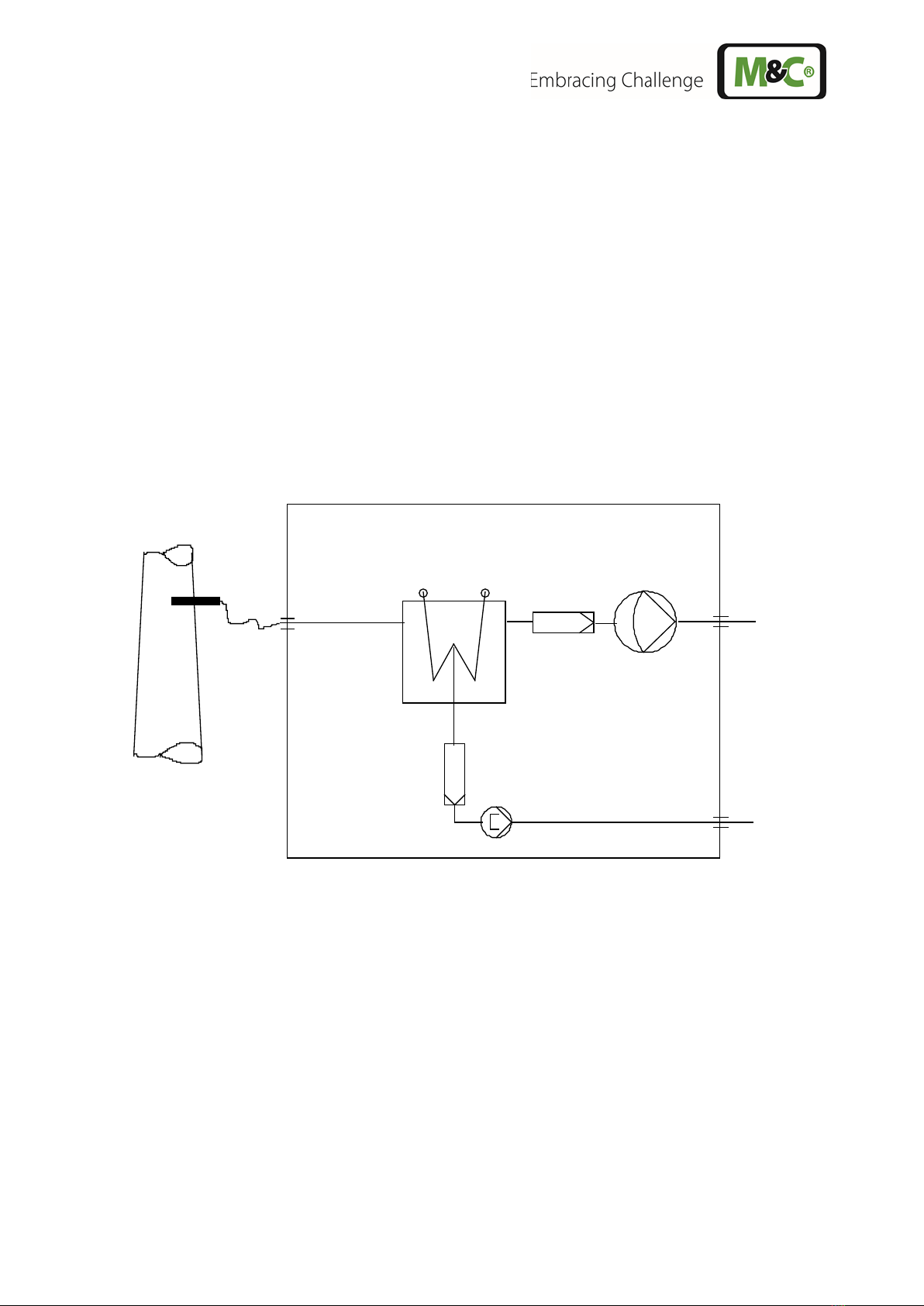
Figure 1 PSS-5 and PSS-5/3 gas flow diagram ..............................................................................8
Figure 2 Design of the conditioning units PSS-5 and PSS-5/3......................................................10
Figure 3 Sample gas connection ..................................................................................................14
Figure 4 Heated sample line connection with special adapter.......................................................16
Figure 5 Electrical connection and main switch ............................................................................17
Figure 6 Circuit diagram PSS-5 and PSS-5/3, 115 V and 230 V...................................................26

4 PSS-5 | 1.00.03 www.mc-techgroup.com
HEAD OFFICE
M&C TechGroup Germany GmbH Rehhecke 79 40885 Ratingen Germany
Telephone: 02102 / 935 – 0
Fax: 02102 / 935 – 111
E - mail: info@mc-techgroup.com
www.mc-techgroup.com
1 GENERAL INFORMATION
The product described in this operating manual has been examined before delivery and left our works
in perfect condition related to safety regulations. In order to keep this condition and to guarantee a
safe operation, it is important to heed the notes and prescriptions made in this operating manual.
Furthermore, attention must be paid to appropriate transportation, correct storage, as well as
professional installation and maintenance work.
All necessary information a skilled staff will need for appropriate use of this product are given in this
operating manual.
2 DECLARATION OF CONFORMITY
CE - Certification
The product described in this operating manual complies with the following EU directives:
EMC-Instruction
The requirements of the EU directive 2014/30/EU “Electromagnetic compatibility“ are met.
Low Voltage Directive
The requirement of the EU directive 2014/35/EU “Low Voltage Directive“ are met.
The compliance with this EU directive has been examined according to DIN EN 61010.
RoHS Directive
The requirements of the RoHS2 (‘Restriction of Hazardous Substances 2’) directive 2011/65/EU and its
annexes are met.
Declaration of conformity
The EU Declaration of conformity can be downloaded from the M&C homepage or directly requested
from M&C.

www.mc-techgroup.com PSS-5 | 1.00.03 5
3 SAFETY INSTRUCTIONS
Please take care of the following basic safety procedures when mounting, starting up or
operating this equipment:
Read this operating manual before starting up and use of the equipment. The information and
warnings given in this operating manual must be heeded.
Any work on electrical equipment is only to be carried out by trained specialists as per the regulations
currently in force.
Attention must be paid to the requirements of VDE 0100 (IEC 364) when setting high-power electrical
units with nominal voltages of up to 1000 V, together with the associated standards and stipulations.
Check the details on the type plate to ensure that the equipment is connected to the correct mains
voltage.
Protection against touching dangerously high electrical voltages:
Before opening the equipment, it must be switched off and hold no voltages. This also applies to any
external control circuits that are connected.
The device is only to be used within the permitted range of temperatures and pressures.
Check that the location is weather-protected. It should not be subject to either direct rain or moisture.
The gas conditioning systems PSS-5 and PSS-5/3 must not be used in hazardous areas.
Installation, maintenance, monitoring and any repairs may only be done by authorized personnel
with respect to the relevant stipulations.
4 WARRANTY
In case of a device failure, please contact immediately M&C or your M&C authorized distributor.
We have a warranty period of 12 months from the delivery date. The warranty covers only
appropriately used products and does not cover the consumable parts. Please find the complete
warranty conditions in our terms and conditions.
The warranty includes a free-of-charge repair in our production facility or the free replacement of the
device. If you return a device to M&C, please be sure that it is properly packaged and shipped with
protective packaging. The repaired or replaced device will be shipped free of delivery charges to the
point of use.

6 PSS-5 | 1.00.03 www.mc-techgroup.com
5 USED TERMS AND SIGNAL INDICATIONS
DANGER!
This means that death, severe physical injuries and/or important
material damages will occur in case the respective safety measures
are not fulfilled.
WARNING!
This means that death, severe physical injuries and/or important
material damages may occur
in case the respective safety
measures are not fulfilled.
CAUTION!
This means that minor physical injuries may occur in case the
respective safety measures are not fulfilled.
CAUTION!
Without the warning triangle means that a material damage may
occur in case the respective safety measures are not met.
ATTENTION
This means that an unintentional situation or an unintentional status
may occur in case the respective note is not respected.
NOTE!
These are important information about the product or parts of the
operating manual which require user’s attention.
QUALIFIED PERSONNEL
These are persons with necessary qualification who are familiar with
installation, use and maintenance of the product.
High voltages!
Protect yourself and others against damages which might be caused
by high voltages.
Corrosive!
These substances destroy living tissue and equipment upon contact.
Do not breathe vapors; avoid contact with skin and eyes.
Wear protective gloves!
Working with chemicals, sharp
objects or extremely high
temperatures requires wearing protective gloves.
Wear safety glasses!
Protect your eyes while working with chemicals or sharp
objects.
Wear safety glasses to avoid getting something in your eyes.

www.mc-techgroup.com PSS-5 | 1.00.03 7
Wear protective clothes!
Working with chemicals, sharp objects or extreme
ly high
temperatures requires wearing protective clothes.

8 PSS-5 | 1.00.03 www.mc-techgroup.com
6 INTRODUCTION
The portable gas conditioning systems PSS-5 and PSS-5/3 have been especially designed, so that
precise gas analysis can be carried out in any place and at any time.
The entire gas conditioning system is housed in a compact and robust aluminium framed protective
case which ensures that the components can be removed easily, and gas analysis carried out quickly,
safely and with a minimum amount of maintenance.
7 APPLICATION
The gas conditioning system is ideally suited for both intermittent and continuous operation.
The components of the PSS-5 and PSS-5/3 systems are intended for "standard use." We also provide
a wide range of additional equipment and other components if special measurements are required.
Gas sample probe, stainless steel 316, Ø 4/6 mm, length 0.5 m
Gas sample line, PVC hose, Ø 4/6 mm, length 3 m
Gas cooler ECP1000 or ECP3000
Fine filter FP-2T, filter element fineness 2 µm
Sample gas diaphragm pump N3KPE or N9KPE
Pre-filter PF 2
Peristaltic pump SR25.1 for continuous removal of condensate
Figure 1 PSS-5 and PSS-5/3 gas flow diagram

www.mc-techgroup.com PSS-5 | 1.00.03 9
8 TECHNICAL DATA
Gas Conditioning Type
PSS-5
PSS-5/3
Gas outlet dew point
Range of adjustment: +2 to +15 °C [35.6 to 59 °F], factory
setting: +5 °C [41 °F]
Gas outlet dew point stability
At const. conditions: < ±0.1 °C [±0.18 °F]
Gas inlet temperature
Max. 80 °C* [176 °F*], optional: max. 180 °C* [356 °F*] with
stainless steel bulkhead union
Gas inlet water vapor saturation
Max. +80 °C* [176 °F*]
Gas flow rate
Max. 150 Nl/h*
Max. 350 Nl/h*
Ambient temperature
+5 to +40 °C* [41 to 104 °F*]
Storage temperature
-25 °C to +65 °C [-4 to 149 °F]
Pressure
0.7 to 1.4 bar abs.*
Total cooling capacity
Max. 50 kJ/h
Max. 90 kJ/h
Number of gas inlets
1
Number of gas outlets
1, optional:
max. 4
Medium connections Tube connections DN 4/6
Material of sample contacting parts
Stainless steel, glass, PPH, PVC, PVDF, PTFE, Novoprene
®
Optional: Viton®for gas sample line, Part No. 01G9025
Ready for operation
Approx. 10 min.
Mains power supply
230 V/50 Hz ±10 % or 115 V/60 Hz ±10 %
Power consumption
Max. 240 VA
Option temperature controller and heated sample line:
230 V max. 1620 VA
115 V max. 930 VA
Fuse protection
4 A
T
, 5 x 20 mm
With option temperature controller and heated sample line:
10 A
T
, 5 x 20 mm
Electrical connection
Cold appliance plug with 2 m [6.6 ft] cable
Case protection
IP20 (EN 60529)
Case type
Portable aluminium framed protective case
Case dimensions (H x W x D)
440 x 540 x 255 mm [approx. 17.3“ x 21.3“ x 10“]
Weight
Approx. 18.5 kg [40.8 lbs]
Approx. 20.0 kg [44.1 lbs]
Options
Temperature controller:
Flow meter (optionally):
Range of control: 0 to 200 °C [32 to 392 °F]
Input: PT100
7 to 70 Nl/h air, 15 to 150Nl/h air, 25 to 250 Nl/h air,
50 to 500 Nl/h air
Quantity: max. 4
Electrical equipment standard
EN 61010
PPH=Polypropylene, PTFE=Polytetrafluoroethylene (Teflon®), PVC=Polyvinyl chloride, PVDF=Polyvinylidenfluoride
Viton®, Teflon® are registered Trademarks of DuPont Performance elastomers
* Maximum values in technical data must be rated in consideration of total cooling capacity at 25 °C [77 °F] ambient
temperature and an outlet dew point of 5 °C [41 °F].

10 PSS-5 | 1.00.03 www.mc-techgroup.com
9 DESCRIPTION
Cooler
ECP
>°C
ON
<°C
EIN
Meßgas
AUS
AUS
Konden sat
max. 1800VA
1
1
2
3
4
2
3
4
GL18
GL25
11
255
540
440
Figure 2 Design of the conditioning units PSS-5 and PSS-5/3
All components of the gas conditioning system are built into a portable case and are freely
accessible. The case door can be opened easily to the left by loosening the tension locks
mounted on the side and top of the case.
The installation of the gas cooler and a corresponding diaphragm measuring gas pump
depends on the required maximum gas volume flow. The possible combinations are summarised in
the following table:
PSS-5...
Type of cooler
Max. gas flow [Nl/h]
Sample gas pump
PSS-5
ECP1000
150
N 3 KPE
PSS-5/3
ECP3000
350
N 9 KPE
The minimum amount of flow is determined by the sample gas pump (see chapter 8). If the required
minimum total flow rate is not reached, excessive overpressure can lead to premature destruction of
the pump diaphragm.
The gas cooler is equipped with a Duran glass heat exchanger as standard. Heat exchangers in
PVDF or stainless steel are optionally available.
The FP-2T fine filter (2 µm filter porosity) installed upstream of the sample gas pump provides
the necessary solids separation.
The overtemperature alarm contact (+8 °C [46.4 °F]) of the cooler automatically regulates the
switching on and off of the sample gas pump.

www.mc-techgroup.com PSS-5 | 1.00.03 11
The resulting condensate is continuously discharged by a peristaltic pump type SR25.1 .
A pre-filter type PF2 is installed in the condensate line between the heat exchanger and the
peristaltic pump. This protects the pump from particle contamination in the condensate.
The 4/6 mm tube connections for the condensate and sample gas lines 11 are located on the right
side of the case (see Figure 2 and Figure 5).
A stainless steel sample tube (length 0.5 m, Ø 6 mm) and 3 m PVC sample tubing (4/6 mm) are
included as standard.
The ventilation grids in the lid and in the left side wall of the case provide sufficient convex forced
ventilation.
Options:
The PSS-5 and PSS-5/3 sample gas conditioning unit can be equipped at the factory with a maximum
of four sample gas outlets. Each sample gas outlet can be controlled according to the specified volume
flow range (see table on page 9) by the optional installation of a flow meter type FM40 with needle
valve. Unused mounting holes for sample gas outputs or flow meters are closed by blind caps.
To protect the downstream analyzers against liquid ingress and to increase the operational reliability
of the entire system, we recommend the installation of a liquid alarm sensor type LA1S. For this
purpose, the FP-2T fine filter installed as standard is replaced at the factory by the FP-2T-D fine filter
with built-in liquid alarm sensor. The LA1.4 electronic controller is located on the terminal support rail
(Figure 2), in the upper part of the case. The LA electronics automatically shuts off the sample gas
pump in the event of a liquid alarm. The alarm is indicated by a red LED. If there is no alarm, a green
LED will be on.
The PSS-5 and PSS-5/3 sample gas conditioning units can optionally be equipped with a sample gas
inlet (see Figure 3, Part No. 01G9060) for connecting a heated sample line. The existing anti-kink
protection must only be used for heated sample lines of connection type "C" (Part No. 03B1012).
Assembly instructions can be found in the appendix.
It is also possible to connect the heated sample line Part No. 01B4036 in connection with the gas
sample probe PSP 4000.
The temperature controller 701 (Part No. 01G9055) required to control the heated line is factory-
installed on the terminal support rail (Figure 2).
A 3-way ball valve (Part No. 01G9046) or a 5-way ball valve (Part No. 01G9045) can optionally be
installed in the inlet of the gas conditioning unit for test gas feed or sample gas switching.

12 PSS-5 | 1.00.03 www.mc-techgroup.com
10 RECEIPT OF GOODS AND STORAGE
The gas conditioning and sampling systems PSS-5 and PSS-5/3 are completely pre-installed units.
•Immediately after arrival take the gas conditioning system and possible special accessories
carefully out of the packaging material.
•Compare the goods with the items listed on the delivery note;
•Check the goods for any damage caused during delivery and, if necessary, notify your transport
insurance company without delay of any damage discovered.
NOTE!
The gas conditioning unit should be stored in a protected
frost-free area!

www.mc-techgroup.com PSS-5 | 1.00.03 13
11 INSTALLATION INSTRUCTIONS
NOTE!
The case should be placed on an even horizontal surface to
ensure a secure and stable position.
The operating position is exclusively vertical. Only in this case is
the proper condensate separation and discharge in the heat
exchanger of the cooler guaranteed.
The gas conditioning case should be set up away from heat
sources and freely ventilated so that no unwanted heat
accumulation occurs.
For outdoor installation, adequate protection against direct
sunlight and moisture must be provided. In winter, the
installation site must be frost-free; observe the protection class
of the case.
To ensure the operational safety of the portable gas conditioning
unit and the downstream analyzers and to avoid false alarms,
the sample gas conditioning unit must not be used outside the
specified temperature range.
Downstream analyzers must always be operated at temperatures
well above the specified gas output dew point of +5 °C. The
temperature range of the downstream analyzers must not be
exceeded. This avoids any condensation of the gas in the
connecting lines to the analyzers.
Unheated gas sample lines must be installed with a gradient down
to the cooler. Condensate pre-separation is then not necessary.

14 PSS-5 | 1.00.03 www.mc-techgroup.com
12 SUPPLY CONNECTIONS
12.1 TUBE CONNECTIONS
NOTE!
Do not swap tube connections; connections are marked
accordingly.
After connecting all lines, the tightness must be checked.
Figure 3 shows the possible medium connections. These are located recessed in a special mounting
frame on the right side of the sample gas conditioning case.
Option:
Mounting of max. 4 FM40
flowmeters possible
EIN
Meßgas
AUS
AUS
Kondensat
1
1
2
3
4
2
3
4
Condensate
Outlet
Sample gas
Outlet
(Option: max. 4)
Sample gas
Inlet
Option:
Electrical connection
for heated sample line
max. 6A, (230V/50Hz or 115V/60Hz)
Figure 3 Sample gas connection
All tube connections are equipped with 4/6 mm sealing ring threaded hose couplings made of
polypropylene (PP) for gas input temperatures of up to a maximum of 80 °C [176 °F] (see chapter 8).
If heated sample lines are used, whereby the gas input temperatures are increased up to a maximum
of 180 °C [356 °F], additional bulkhead unions made of stainless steel are recommended.
Dimension 4/6 mm connecting tubes are used as standard.

www.mc-techgroup.com PSS-5 | 1.00.03 15
The sample gas tubes or condensation tubes, are to be assembled as follows:
•Remove the union nut from the sealing ring couplings by turning it anti-clockwise. The nut should
be removed from the thread with great care so as to ensure that the loose sealing ring in the nut is
not lost.
•Place the union nut over the connecting tube.
•Place the sealing ring over the connecting hose with the thicker bead towards the nut.
•Place the hose over the nipple on the thread.
NOTE!
The tightness of the connections can only be guaranteed if the
connecting tube has a straight rim (hose cutter).
•The union nut is to be screwed tight by hand.
The tube will no longer be able to slip off, and is now compression-proof.
The tubes are to be removed in the reverse order.
WARNING!
Aggressive condensate is possible.
Wear protective glasses and proper protective clothing!

16 PSS-5 | 1.00.03 www.mc-techgroup.com
12.1.1 CONNECTING THE HEATED SAMPLE LINE WITH SPECIAL ADAPTER (OPTION)
Figure 4 Heated sample line connection with special adapter
•Place the special adapter on the PTFE tube according to the drawing seen above;
•Place the support sleeve into the PTFE tube;
•Insert the Teflon tube as far as possible into the 'Sample gas IN' bulkhead fitting and hand-tighten
the adapter;
•Tighten the adapter 1 1/4 turns with a wrench (SW 14), while holding the lock nut of the Schott
screw connection with a wrench (SW 15);
•Insert the 10mm pipe of the heating cable into the adapter as far as possible and hand-tighten with
the union nut;
•Tighten the union nut 1 1/4 turns with the wrench (SW 19), holding the adapter in place with the
wrench;
The screw connection is now cut gas-tight and can be loosened as often as required.
12.2 ELECTRICAL CONNECTIONS
WARNING!
False supply voltage can demage
the equipment. When
connecting the equipment, please ensure that
the supply voltage
is identical with the information provided on the model type
plate!
NOTE!
For the erection of power installations with rated voltages up to
1000V, the requirements of VDE 0100 and relevant standards and
specifications must be observed!
The main circuit is equipped with a fuse corresponding to the
nominal current (over current protection); for electrical details see
technical data.
Sample gas IN
Bulkhead union
Back ferrule 6 mm Ø ID
Back ferrule
10 mm Ø ID
Sealing ring
10 mm Ø ID
Sealing ring
6 mm Ø ID
Support sleeve
4 mm Ø OD
Union nut 10 mm Ø ID
Heated sample line
Adapter
PSS-5
PSS-5/3

www.mc-techgroup.com PSS-5 | 1.00.03 17
The PSS-5 and PSS-5/3 gas conditioning systems are available with either 230V/50 Hz or with
115V/60 Hz (for circuit diagram see Appendix). A 4 A fuse is used on all models as fuse protection.
The fuse is located on the clamp mounting rail (see Figure 2). When optionally using a temperature
controller with heated line, the overload protection increases to 10 A.
The electrical connection is made via a cold appliance plug with 2 m cable on the left side of the case.
The power socket is equipped with a two-pole main switch.
Main switch and
cold appliance plug socket
0
Ventilation grids
Figure 5 Electrical connection and main switch
Option “ heated sample line”:
For the electrical supply of a heated sample line with PT-100 sensor and/or the connection of other
heated components, e.g. heated sample gas probe or heated filter, a connection socket as shown in
Figure 3 is available. The maximum connected load is 6 A, 1380 W for the 230 V sample gas
conditioning or 6 A, 690 W for the 115 V version.
The maximum length of the usable heated sampling line is calculated as follows:
Max. connected load [W] - Power consumption of heated components (e.g. sample probe) [W]
L(m)=
Power consumption heated line per meter [W/m]

18 PSS-5 | 1.00.03 www.mc-techgroup.com
13 COMMISSIONING
Before commissioning, the plant-specific and process-specific safety measures must be observed.
NOTE!
Before connecting the equipment to the supply voltage, the
main switch must be in position “0”.
The following steps must be carried out before initial commissioning:
•Plug the power plug of the supplied power cable into the power socket;
•Connect the heated cable (optional);
WARNING!
When operating the sample gas conditioning system with a
heated sample gas line, the temperature must be checked at the
temperature controller.
•Connect the mains plug to the mains;
•Switch the main switch to position 'I'.
•Set the desired temperature on the temperature controller.
Type 701: The digital display of the controller shows the actual value of the heated sample line after
switching on the sample gas conditioning unit. The controller is set to 0 °C [32 °F] on delivery. Briefly
press the P key to change the set point. SP appears in the display and then the display changes to
the adjusted set point. Use the arrow keys to set the desired value. After 60 seconds, the display
automatically changes to the actual value.
The sample gas cooler is ready for operation after approx. 10 minutes. The overtemperature alarm
contact of the cooler switches on the sample gas pump automatically when the cooler reaches the
temperature of +8°C [46.4 °F].
NOTE!
The following minimum gas flow rates result from the requirement
of the maximum pressure-
side load of the sample gas pumps N3
KPE and N9 KPE of 1.4 bar abs:
N 3 KPE approx. 60l/h air,
N 9 KPE approx. 200l/h air.
If the required minimum total flow rate is not reached, excessive
overpressure can lead to premature destruction of the pump
diaphragm.
For long-
term measurements with a high dust content in the
sample gas, a suitable gas
sampling probe must be provided to
protect the sampling line from blockages.

www.mc-techgroup.com PSS-5 | 1.00.03 19
14 CLOSING DOWN
NOTE!
The installation site of the gas conditioning unit must remain frost-
free even when the unit is switched off.
No special measures are to be taken in the event of short-term shutdowns of the gas conditioning
system.
In the case of long-term shutdowns, for example after a completed series of measurements, it is
recommended to purge the gas conditioning system with fresh air or inert gas. A flushing time of 3 to
5 minutes is sufficient under normal conditions. Condensate residues must also be removed from the
system.
WARNING!
Aggressive condensate is possible.
Wear protective glasses and proper protective clothing!
15 MAINTENANCE
Before carrying out maintenance work, the plant-specific and process-specific safety measures must
be observed!
WARNING!
Dangerous voltage.
Before carrying out any work on the gas conditioning unit, move
the main switch to position “0” and pull out the mains plug!
The maintenance cycles depend on the process conditions and must therefore be determined for each
specific application.
All parts to be serviced are easily accessible and installed in the sample gas conditioning case. These
are (see Figure 2):
•The filter element of the preliminary filter FP-2T .

20 PSS-5 | 1.00.03 www.mc-techgroup.com
NOTE!
In order to protect downstream analyzers, the wet filter element
must always be replaced after a condensate ingress.
•Peristaltic pump pre-filter PF2 ; The pre-filter must be replaced at regular intervals if the
condensate is loaded with particles. The "disposable filter" is inserted into the pump tube on the
suction side (see Figure 2) and can be easily replaced;
•Check the tubing of the SR25.1 condensate pump every six months and replace it if necessary
(see operating instructions in the appendix);
•Check the diaphragm of the gas feed pump N3 KPE or N9 KPE every six months and replace
if necessary.
Other manuals for PSS Series
5
This manual suits for next models
2
Table of contents
Popular Test Equipment manuals by other brands

Horotec
Horotec VIBRATO MSA 19.709 operating manual

WIKA
WIKA Pascal ET operating instructions

Industrial Test Systems
Industrial Test Systems Spa eXact EZ quick start guide

B+K precision
B+K precision 8500 user manual

System Sensor
System Sensor Zonecheck Installation and maintenance instructions

TECGAUSS
TECGAUSS BT010 user manual