MANGO POWER M User manual

MANGO POWER M
Troubleshoong Guide

01 ©2023 MANGO POWER. All rights reserved. MANGO POWER, the MANGO POWER logo, MANGO POWER M, M Hybrid Inverter 12kW, M Baery 5kWh, M Smart Screen,
MANGO POWER mPanel Smart, MANGO POWER App, and other trademarks or service names are the trademarks of MANGO POWER, inc. Date subject to change.
Baery maintenance
Do dust cleaning and baery performance checks every month to ensure the operability of the product.
Scrapped products should be recycled immediately by the specified qualified vendor instead of being discarded at will and
risking safety hazards or severe environmental contaminaon.
Baeries in long-term storage should be charged to 50% - 60% SoC every 6 months.
If the M Baery displays any warnings or faults, users can perform troubleshoong based on the states of indicator lamps and
the buzzer.
1.2.1 Notes on indicator lamps:
1.2.2 Troubleshoong
1.2 M Baery Troubleshoong
Status Normal/Alarm/Protecon
Shutdown
Standby
Charging
Sleep
Normal
Alarm
ON/OFF RUN ALM
Off Off Off
On Flash 1 Off
On Flash 1 Flash 3
Alarm
Overcharge protecon
Temperature/ overcurrent/
failure protecon
On On
On On Off
Flash 3
Normal On On Off
Based on SoC indicaon
Based on SoC indicaon (max. SoC indicaon
LED Flash 2)
Standby state
Module LV
Normal
Discharging
Alarm
On Flash 3 Off
On Flash 3 Flash 3
Based on SoC indicaon
Off Off Off Off Off Off
On On On On On On
All off
SoC indicator LED Remarks
LED flashes (Flash 2) on max. SoC. ALM doesn’t
flash on overcharge alarm
No grid power, indicator lamp toggled to standby state
On Off On Off Off Off Off Off Off Stop charging
Undervoltage protecon
Temperature, over current, short circuit,
reverse connecon, faliure protecon
On Off Off Off Off Off Off Off Off
On Off On Off Off Off Off Off Off
Stop discharging
Failure Off Off Off Off Off Off Off Off Off Stop charging/discharging
Stop discharging
Serial No.
1No DC output aer startup
No working of the indicang
lamp aer startup
Indicang insufficient
electric quanty
Short power supply me
Unstable output voltage
aer startup
Communicaon failure
Too low charging voltage
The baery pack is not full charged
BMS is interrupted
Problems in communicaon line
Restart using the Reset Switch
Check the address seng of the address switch,
ports and lines
Adjust the floang charge voltage of the switching
power supply to the required parameters
Check the charging voltage, current and other
parameters of the switching power supply
Over-discharge protecon due to low
baery voltage
BMS is in dormant state
Carry out charging
Restart using the Reset Switch2
3
4
Fault Phenomenon Analysis of Causes Soluons
5
6
Notes on LED flashes
Way of flashes On Off
Flash 1 0.25s 3.75s
Flash 2 0.5s 0.5s
Flash 3 0.5s 1.5s
Maintenance of inverters
1.1 Regular Maintenance
1 Troubleshoong and Maintenance
Inspect inverters every 6 months to ensure that the radiator of the inverters is not covered by anything. If it is,
stop the inverter and clean its radiator.
Inspect inverters every 6 or 12 months for any signs of damage in cables, fixings, terminals, and the general
inverter device.
Inspect inverters every 6 months for anomalies in operaon, heat, or noise parameters.

02
©2023 MANGO POWER. All rights reserved. MANGO POWER, the MANGO POWER logo, MANGO POWER M, M Hybrid Inverter 12kW, M Baery 5kWh, M Smart Screen,
MANGO POWER mPanel Smart, MANGO POWER App, and other trademarks or service names are the trademarks of MANGO POWER, inc. Date subject to change.
Note:
The buzzer is designed to be enabled or disabled through the primary computer. It is disabled by default on shipment.
In case of a fault, the buzzer will sound for 0.25s in every 1s. In case of a protecon noce, it buzzes for 0.25s in every
2s (excluding overvoltage protecon). In case of an alarm, it buzzes for 0.25s in every 3s (excluding overvoltage
protecon).
Notes on reset buon (RST): When BMS is in sleep mode, press and hold the buon for 3 - 6s, the guard is then
acvated and the LED indicator lamps will light up for 0.5s in sequence from “RUN”. When BMS is acve, press and hold
the buon for 3 - 6s, the guard will then sleep and the LED indicator lamps will light up for 0.5s in sequence from Min.
SoC. When BMS is in sleep mode, press and hold the buon for 6 - 10s, the guard is then reset and all the LED
indicator lamps will light up simultaneously for 1.5s.
Upon reseng, the BMS sll reserves the parameters and funcons set by the primary computer. If you wish to restore
the original parameters, you can do it through the “Restore defaults” opon on the primary computer. However, the
operaon records and stored data (e.g. SoC, cycles, protecon records, etc.) will remain unchanged.
Common faults and corresponding soluons are as follows:
If the M Hybrid Inverter displays any warnings or faults, users can perform troubleshoong based on the state
of the LEDs and the alarm/fault info on the Smart Screen.
If the dot on the le of a fault entry is red, it means
this fault is current. If the dot is gray, it means that
this fault doesn’t exist anymore.
1.3 Troubleshoong According to the M Smart Screen
1.3.1 States Indicated by the M Hybrid Inverter LEDs
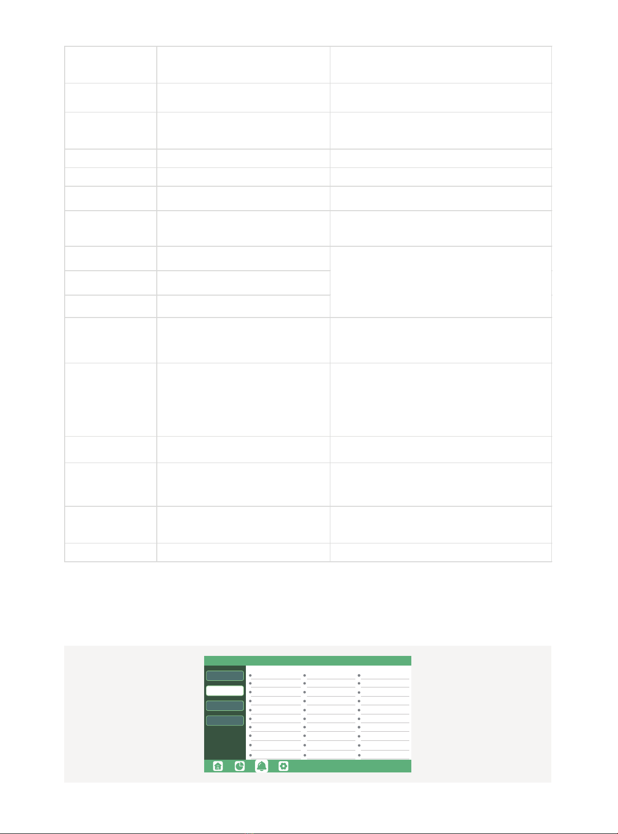
1.3.2 Faults Display on the M Smart Screen
LEDIndicaon Remarks Suggesons
On Normal
Flash Firmware is upgrading Wait for the upgrade to finish
YellowLEDOn Warning. The inverter is working Troubleshoong required
Red LEDOn Fault. The inverter stopped working Troubleshoong required
Green LED
Alarm record
Fault st a t us
Fault record
Alarm status
M3 Rx failure
Fault C
Para Comm error
Para Spec Diff
M8 Tx failure
Eps connect fault
Neutral fault
Bus sample fault
Eps power reversed
Para Sync loss
M8 Rx fault
Inconsistant
Model fault
Fault A Fault B
Fault D Fault E
Para rating Diff
Eps sho rt circuit
Bus short circuit
Relay fault
M3 Tx failure
Vbus over range
PV volt highHard o ver Curr
PV short circuit
Temperature fault
Para Gen unAccord
Para p rim ary loss
Para Phase set error
Fault Meaning Troubleshoong
M3 Rxfailure M3 microprocessor fails to receive data fromDSP
Model fault Incorrect model value
1. Check ifthe L1, L2 and N wires are connected correctly at
inverter BACKUP LOADoutput port;
2. Disconnect the LOADbreaker to see iffault remains. Iffault
persists, contact your supplier.
BACKUP power reversed Inverter detected power flowing into BACKUP port
Bus short circuit DC Bus is short circuited
Relay fault Relay abnormal
M8 Txfailure DSP fails to receive data fromM8 microprocessor
M3 Txfailure DSP fails to receive data fromM3 microprocessor
Restart inverter, ifthe error sll exists, contact your supplier.
BACKUP short circuit Inverter detected short-circuit on BACKUP output
terminals
Restart inverter, ifthe error sll exists, contact your supplier.
03 ©2023 MANGO POWER. All rights reserved. MANGO POWER, the MANGO POWER logo, MANGO POWER M, M Hybrid Inverter 12kW, M Baery 5kWh, M Smart Screen,
MANGO POWER mPanel Smart, MANGO POWER App, and other trademarks or service names are the trademarks of MANGO POWER, inc. Date subject to change.
If the dot on the le of a fault entry is yellow, it means this fault is current. If the dot is gray, it means this fault
doesn’t exist anymore.
1.3.3 Alarms Displayed on the M Smart Screen
Alarm r e cord
Fault status
Fault r e cord
Alarm s t atus
Offgrid d cv hig h
RSD Active
Para Pha se loss Para no BM set
PV short circuit
Bat volt hig h
Fw mismatch
AFCI hig h
Trip b y dci hig h
Offgrid o verload
Meter reversed
Bat fault
Trip b y iso low
GFCI module fault
Bat volt low
Bat Com failure
AFCI Com failure
Trip b y no AC
Trip by gfci high
Bat open
Offgrid o vervolt
Meter Com failure
Fan stuck
Trip by Vac abnormal
Auto test failure
Lcd Com failure
Breversedat
Para m ulti BM set
Trip by Fac abnormal
Alarm A
Vbus over range DC Bus voltage too high
Please check ifthe PVstring voltage is within the inverter
specificaon. Ifstring voltage is within range and this fault sll
appears, contact your supplier.
BACKUP connect fault BACKUP LOADport and grid port are connected
mixed up
Check ifthe wires on the BACKUP LOADport and grid port are
connected correctly. Ifthe error sll exists, contact your supplier.
PVvolt high PVvoltage is too high
Please check ifthe PVstring voltage is within the inverter
specificaon. Ifstring voltage is within range and this fault sll
appears, contact your supplier.
Hard over curr Hardware level over current protecon triggered Restart inverter. Ifthe error sll exists, contact your supplier.
Neutral fault Voltage between N and PE is greater than 30V Check ifthe neutral wire is connected correctly
PVshort circuit Short circuit detected on PVinputDisconnect all PVstrings fromthe inverter. Ifthe error persists,
contact your supplier.
Temperature fault Heat sink temperature too high
Install the inverter in a place with good venlaon and no direct
sunlight. Ifthe installaon site is okay, please check ifthe NTC
connector inside the inverter is loose.
Bus sample fault Inverter detected DC bus voltage lower than PVinput
voltage
Inconsistent Sampled grid voltage values ofDSP and M8
microprocessor are inconsistent
M8 Rxfault M8 microprocessor fails to receive data fromDSP
Para Comm error Parallel communicaon abnormal
1.Please check ifthe connecon ofthe parallel cable is loose and
connect it correctly 2.Please check and make sure the PIN status of
CAN communicaon cable fromthe first to the end inverter is
correct.
Para “master”loss No “master”in the Parallel system
1.Ifa “master”has been configured in the system, the fault will be
automacally removed aer the “master”works. Ifso, youcan ignore
it. 2.Ifa “master”has not been configured in the system, and there
are only “slaves”in the system, please set the “master”first. Note:
For single unit running systems, the role ofthe inverter should be set
as “1 phase master”
Para rang DiffRated power ofparallel inverters are inconsistent Please confirmthat the rated power ofall inverters are the same or
contact servicing to confirm.
Para Phase set error Incorrect seng ofphase in parallel
Please confirmthat the wiring ofthe parallel systemis correct first. In
this case, connect each inverter to the grid. The systemwill
automacally detect the phase sequence and the fault will be
automacally resolved.
Para Gen un Accord Inconsistent generator connect in parallel
Some inverters are connected to generators, some are not. please
confirmthat all inverters in parallel are connected to generators
together or none ofthemare connected to generators
Para syncloss Parallel inverter fault Restart inverters. Ifthe error sll exists, contact your supplier.
Restart inverter. Ifthe error sll exists, contact your supplier.

04
©2023 MANGO POWER. All rights reserved. MANGO POWER, the MANGO POWER logo, MANGO POWER M, M Hybrid Inverter 12kW, M Baery 5kWh, M Smart Screen,
MANGO POWER mPanel Smart, MANGO POWER App, and other trademarks or service names are the trademarks of MANGO POWER, inc. Date subject to change.
Meanings of faults and corresponding soluons are as follows:
Alarm MeaningTroubleshoong
Bat comfailure Inverter fails to communicate with baery
Check ifthe communicaon cable is correctly installed and if
youhave chosen the correct baery brand on the M Smart
Screen. Ifall is correct but this error persists, please contact
your supplier.
AFCI comfailure Inverter fails to communicate with AFCI module Restart inverter. Ifthe error persists, contact your supplier.
AFCI high PVarcfault is detected
Check each PVstring for correct open circuit voltage and
short circuit current. Ifthe PVstrings are in good condion,
please clear the fault on the M Smart Screen.
1. Check ifthe communicaon cable is connected correctly
and in good condion.
2. Restart inverter. Ifthe fault persists, contact your supplier
1. Check the baery communicaon cable for the correct
pinout on both the inverter and baery.
2. Check ifyouhave chosen an incorrect baery brand.
3. Check ifthere is a fault on the baery's indicator. Ifthere
is a fault, please contact your baery supplier.
Auto test failure Auto test failed Only applied to Italian model
LCD comfailure M Smart Screen fails to communicate with M3
microprocessor
Fwm mismatchFirmware version mismatch between the
microprocessors
Fan stuckCooling fan(s)are stuck
Tripby gfci high Inverter detected leakage current on ACside 1. Check ifthere is a ground fault on the grid and load side.
2. Restart inverter. Ifthe fault remains, contact your supplier.
Tripby dci high
Inverter detected high DC injecon current on grid
port
Restart inverter. Ifthe fault remains, contact your supplier.
1. Check ifeach PVstring is connected correctly.
2. Restart inverter. Ifthe fault remains, contact your supplier.
GFCI module fault GFCI module is abnormal Restart inverter. Iffault sll exists, contact your supplier
Bat volt high Baery voltage too high Check ifbaery voltage exceeds 59.9V, baery voltage
should be within inverter specificaons.
Bat volt lowBaery voltage too lowCheck ifthe baery voltage is under 40V, baery voltage
should be within inverter specificaons.
Bat open Baery is disconnected frominverter Check baery breaker or baery fuse.
Offgrid overload Overload on BACKUP LOADport Check ifload power on the inverter EPSport is within
inverter specificaons.
Offgrid overvoltage BACKUP voltage is too high Restart inverter. Iffault sll exists, contact your supplier
Meter reversed Meter is connected reversely Check ifthe meter communicaon cable is connected
correctly on the inverter and meter side.
Offgrid dcv high
High DC voltage component on EPSoutput when
running off-grid
Restart inverter. Iffault sll exists, contact your supplier.
RSD Acve Rapid shutdown acvated Check ifthe RSD switch is pressed.
PVshort circuit Inverter detected short circuited PVinput
Meter comfailure PVarcfault is detected
Bat Fault Inverter fails to communicate with the meter
Restart inverter. Iffault sll exists, contact your supplier.
Inspect inverters every 6 months for anomalies in operaon, heat, or noise parameters.
Inspect inverters every 6 months to ensure that the radiator of the inverters is not covered by anything. If it is,
stop the inverter and clean its radiator.

05 ©2023 MANGO POWER. All rights reserved. MANGO POWER, the MANGO POWER logo, MANGO POWER M, M Hybrid Inverter 12kW, M Baery 5kWh, M Smart Screen,
MANGO POWER mPanel Smart, MANGO POWER App, and other trademarks or service names are the trademarks of MANGO POWER, inc. Date subject to change.
We recommend checking and cleaning the fan every 6 months. If the fan is problemac, replace it as illustrated
below. Shut down all systems and wait 5 minutes before dismantling the inverter.
1.4 Replacement of Inverter Fan
a. Open wiring cover
b. Pull out the fan wires
c. Loosen and remove screws
d. Remove fasteners of the fan e. Loosen waterproof connector
f. Remove and replace the fan
g. With a new fan installed, follow
the steps above backwards
Para phase loss Phase loss in parallel system
Please confirmthat the wiring ofthe inverter is correct. If
the
primary
is set to 3 Phase
primary
, the number of
parallel inverters needs to be ≥3. (And the grid input ofeach
inverter should be connected with Grid L1, L2, L3 rightly). If
the
primary
is set to 2x208
primary
, the number of
parallel inverters needs to be ≥2. (And the grid input ofeach
inverter should be connected with Grid L1, L2, L3 rightly)
Para no BM set
primary
isn’t set in the parallel systemPlease set one ofthe inverters in the parallel systemas the
primary
.
Para mulBM set Mulple
primary
have been set in the parallel
system
There are at least two inverters set as
primary
in the
parallel system, please keepone
primary
and the other set
as secondary

Please scan this QR code for
more product informaon
Other manuals for M
1
Table of contents
Other MANGO POWER Batteries Pack manuals


