manuals.online logo
Brands
  1. Home
  2. •
  3. Brands
  4. •
  5. Manitowoc
  6. •
  7. Ice Maker
  8. •
  9. Manitowoc IB Series Quick start guide

Manitowoc IB Series Quick start guide

Other Manitowoc Ice Maker manuals

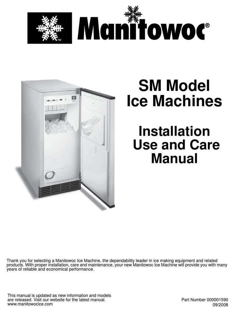
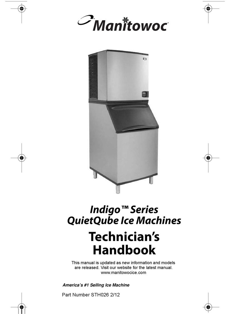
Manitowoc Indigo QuietQube ID0682C User manual

Manitowoc

Manitowoc Indigo QuietQube ID0682C User manual

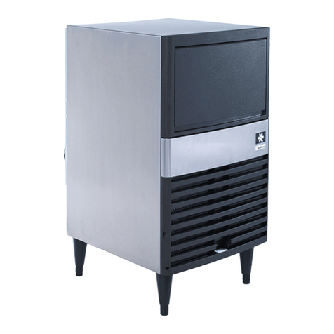
Manitowoc QuietQube Indigo Series User manual

Manitowoc

Manitowoc QuietQube Indigo Series User manual

Manitowoc GR1200A User manual

Manitowoc

Manitowoc GR1200A User manual

Manitowoc G200 Series User manual

Manitowoc

Manitowoc G200 Series User manual

Manitowoc QR0670C User manual

Manitowoc

Manitowoc QR0670C User manual

Manitowoc QuietQube Indigo Series User manual

Manitowoc

Manitowoc QuietQube Indigo Series User manual

Manitowoc PRO MIXER NOX101 User manual

Manitowoc

Manitowoc PRO MIXER NOX101 User manual

Manitowoc UG Series User manual

Manitowoc

Manitowoc UG Series User manual

Manitowoc QM45A User manual

Manitowoc

Manitowoc QM45A User manual

Manitowoc ECS018A User manual

Manitowoc

Manitowoc ECS018A User manual

Manitowoc QM20 Series Owner's manual

Manitowoc

Manitowoc QM20 Series Owner's manual

Manitowoc S series User manual

Manitowoc

Manitowoc S series User manual

Manitowoc RF0244 Instructions for use

Manitowoc

Manitowoc RF0244 Instructions for use

Manitowoc Welbilt Indigo NXT QuietQube User manual

Manitowoc

Manitowoc Welbilt Indigo NXT QuietQube User manual

Manitowoc Indigo Series User manual

Manitowoc

Manitowoc Indigo Series User manual

Manitowoc Indigo NXT User manual

Manitowoc

Manitowoc Indigo NXT User manual

Manitowoc Q130 series Manual

Manitowoc

Manitowoc Q130 series Manual

Manitowoc 30" Q-MODEL ICE MACHINES MYLAR STRIP 7600153 User manual

Manitowoc

Manitowoc 30" Q-MODEL ICE MACHINES MYLAR STRIP 7600153 User manual

Manitowoc RNS0244 User manual

Manitowoc

Manitowoc RNS0244 User manual

Manitowoc CSA-151 series Operating instructions

Manitowoc

Manitowoc CSA-151 series Operating instructions

Manitowoc UnderCounter QM45 Instructions for use

Manitowoc

Manitowoc UnderCounter QM45 Instructions for use

Manitowoc QM20 Series Owner's manual

Manitowoc

Manitowoc QM20 Series Owner's manual

Manitowoc CrystalCraft Premier User manual

Manitowoc

Manitowoc CrystalCraft Premier User manual

Manitowoc Indigo Series User manual

Manitowoc

Manitowoc Indigo Series User manual

Popular Ice Maker manuals by other brands

camry CR 8073 user manual

camry

camry CR 8073 user manual

Sub-Zero 315I Planning information

Sub-Zero

Sub-Zero 315I Planning information

Kenmore 2217402A Use & care guide

Kenmore

Kenmore 2217402A Use & care guide

Cornelius WM600 Installation & owner's manual

Cornelius

Cornelius WM600 Installation & owner's manual

GE XPIO43SCSS owner's manual

GE

GE XPIO43SCSS owner's manual

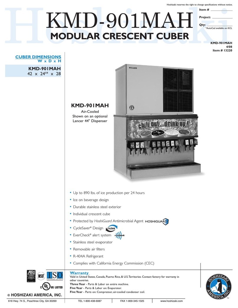
Hoshizaki KMD-901MAH Specifications

Hoshizaki

Hoshizaki KMD-901MAH Specifications

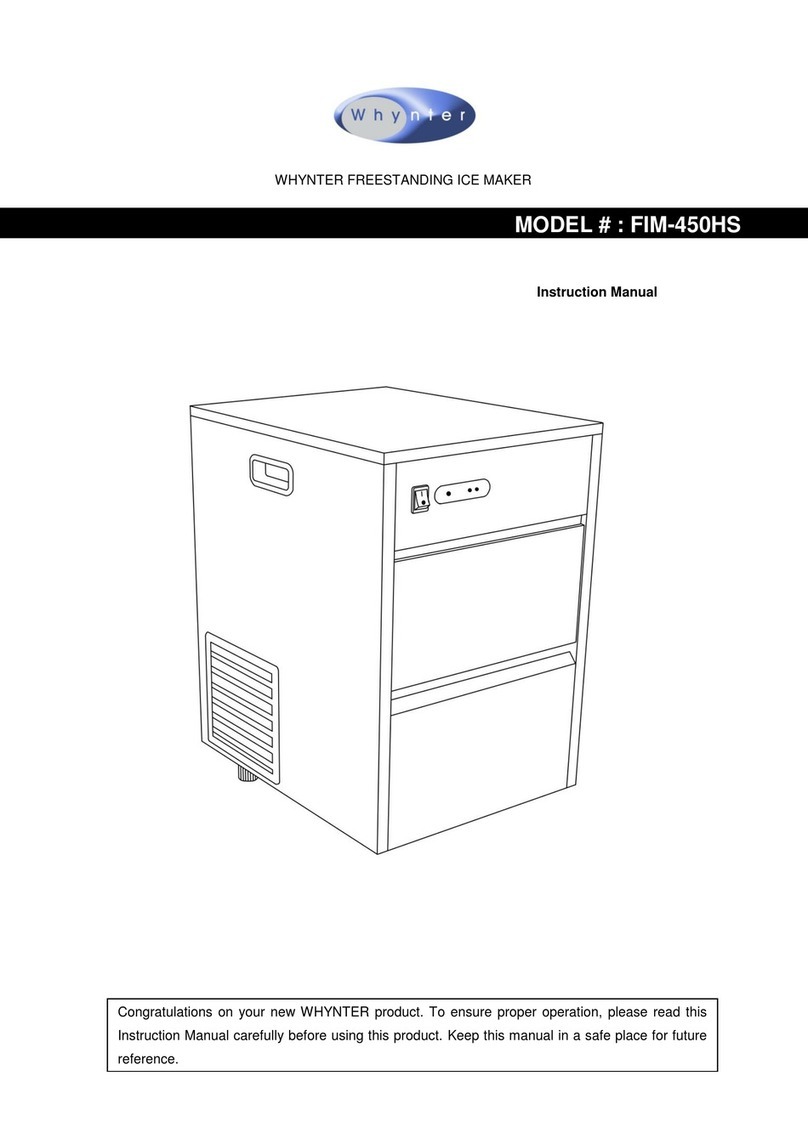
Whynter FIM-450HA instruction manual

Whynter

Whynter FIM-450HA instruction manual

Unold 48945 Instructions for use

Unold

Unold 48945 Instructions for use

Andrew James AJ000522 manual

Andrew James

Andrew James AJ000522 manual

Scotsman CME1356 user guide

Scotsman

Scotsman CME1356 user guide

Scotsman ACM 25 Service manual

Scotsman

Scotsman ACM 25 Service manual

Kärcher IP 120 manual

Kärcher

Kärcher IP 120 manual

U-Line SS1095 Quick referenc guide

U-Line

U-Line SS1095 Quick referenc guide

Maytag MIM1554WRS - Ice Maker User instructions

Maytag

Maytag MIM1554WRS - Ice Maker User instructions

Igloo ICE102-WHITE user manual

Igloo

Igloo ICE102-WHITE user manual

Hoshizaki KM-630MAH instruction manual

Hoshizaki

Hoshizaki KM-630MAH instruction manual

Princess Yonanas user manual

Princess

Princess Yonanas user manual

Unold 48946 Instructions for use

Unold

Unold 48946 Instructions for use

manuals.online logo
manuals.online logoBrands
  • About & Mission
  • Contact us
  • Privacy Policy
  • Terms and Conditions

Copyright 2025 Manuals.Online. All Rights Reserved.

MANITOWOC ICE, INC. Address - 2110 S. 26th St., P.O. Box 1720, Manitowoc, WI 54221-1720 USA
Telephone - 920-682-0161 • Service Fax - 920-683-7585 • Web Site - www.manitowocice.com
Parts & Service Communicator
Electronic Bin Thermostat Control
The electronic bin thermostat control is used with ice machines on dispensers or ice machines with pure water
(reverse osmosis or de-ionized). Current production Ice Beverage (IB Model) machines also have the electronic bin
thermostat control replacing the mechanical bin thermostat control.The thermostat is intended to reduce overfill
and condensation issues. If an ice machine has an electronic bin thermostat control, a bin thermostat will be
mounted in the bin.
Bin Thermostat
ELECTRONIC BIN THERMOSTAT CONTROL
The temperature control opens the bin switch (or toggle
switch) circuit when ice contacts the sensor. When ice no
longer contacts the sensor, the circuit closes and the ice
machine starts.
Specifications
Setpoint Range: -30 to 212°F (-34 - 100°C)
CONTROL SETTINGS
Verify control is set properly before proceeding.
Positioning the Touchpad Jumpers
P5 Jumper
The P5 jumper position determines if the touchpad is
locked or unlocked. The control is factory locked; to unlock
move the jumper from one pin to two pins.
Inside of Bin Thermostat Control
P4 Jumper
The P4 jumper labeled Jump 1 is used to set the control for
heating or cooling mode. Jump 2 is used to establish Set-
point at either cut-in or cutout. The Cubers use Diagram A
settings and Nugget/Flake/Chiplet use Diagram B
settings.
Cubers
Nugget/Flake/Chiplet
Display Function Preset Settings
SP Set Point 40
DIF Differential 1
ASD Anti-Short Cycle Delay 1
OFS Temperature Offset 0
SF Sensor Failure Mode 1 - Cubers
0 - Nugget/Flake/Chiplet
115V
240V COM NC NOC
P5
P5 P4
P4
Jump 1
Jump 2
REDLEAD
SENSOR
PROBE
BLACK
LEAD
SENSOR
PROBE
MATCH
WIRING
TO ICE
MACHINE
VOLTAGE
BIN SWITCH
or TOGGLE
SWITCH
WIRE
BIN SWITCH
or TOGGLE
SWITCH
WIRE
KEYPAD
JUMPER
LOCATION
P4
Jump 1
Jump 2
Cooling Mode
Cut-In at Setpoint
Jumper on
Left Pins
Only
Diagram
A
P4
Jump 1
Jump 2
Cooling Mode
Cut-Out at Setpoint
Jumper on
Both Pins
Jumper on
Left Pin Only
Diagram
B
PSC003-04
03/06
Setting Control Setpoint Value
To view and adjust setpoint, follow these steps:
1. Press MENU until the display flashes SP.
2. Press MENU again to display the existing setpoint
value.
3. Press Up or Down (arrows) to change the setpoint
value.
4. Press MENU again to save the new value. The
display returns to the sensed temperature.
NOTE: If no setup entry is made for 30 seconds, the
control reverts to the normal temperature display.
Differential, Anti-Short Cycle Delay, Temperature
Offset, or Sensor Failure Operation
To set or verify the Differential, Anti-Short Cycle Delay,
Temperature Offset or Sensor Failure Operation use
the following method.
Factory Preset Temperature Control Code Settings as
follows:
1. Press and hold MENU until the display changes to
flashing SP.
2. Press up and down (arrows) repeatedly until the
desired function is displayed.
3. Press MENU to display the function’s current
value.
4. Press up and down (arrows) until the desired value
is displayed.
5. Press MENU to save the new value. The display
returns to the sensor temperature.
NOTE: If no setup entry is made for 30 seconds, the
control reverts to the temperature display.
NOTE: Any saved control settings are non-volatile and
remain in the control’s memory during power
interruptions.
Check Procedure
If the control system does not function properly, verify
that the control is wired and set up properly. If the
problem persists use the following procedures to
determine the cause of the problem.
1. Check the proper voltage to the control.
A. Remove the cover, loosen the four cover
screws.
B. Use an AC voltmeter to check the voltage
between the common and 120V or 240V
terminals.
C. The voltage must be between102 and 132
volts for 120V applications, 177 and 264 volts
for 208/230V applications.
D. If the voltage reading is not within the required
range, check the power source and input
power wires for problems.
2. Fault Codes
If the LCD displays an alarm or fault code (SF or EE):
3. Check for proper operation.
NOTE: Perform Steps 1 and 2 before performing this
step.
A. Disconnect the load from the output relay
terminals.
B. Reconnect the sensor leads and supply power
to the control.
C. Replace the cover.
D. Check the control settings for proper values.
E. Press and hold MENU until SP appears.
F. Press up and down (arrows) to change the
setpoint temperature above and below the
sensor temperature until the relay energizes
and de-energizes.
G. If the output relay does not perform as
indicated replace the control.
H. If proper operation of the control is verified,
reconnect the load.
Important
If MENU is not pressed after changing the setpoint
value, the control reverts to the previously
programmed setpoint value.
!
Warning
Line voltage is present inside control. Contact with
line voltage can cause serious injury or death.
Important
Follow these troubleshooting procedures in the
order presented. Do not skip any of the steps in
the procedures.
Fault Code Definition Solution
SF flashing
alternately with OP Opentemperature
sensor or sensor
wiring
See Step 3. Cycle
power to reset control.
SF flashing
alternately with SH Shorted
temperature
sensor or sensor
wiring
See Step 3. Cycle
power to reset control.
EE Program failure Reset the control by
pressing MENU. If
problem persists,
replace the control.