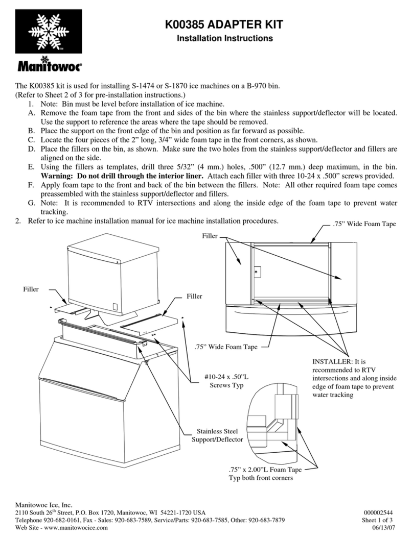
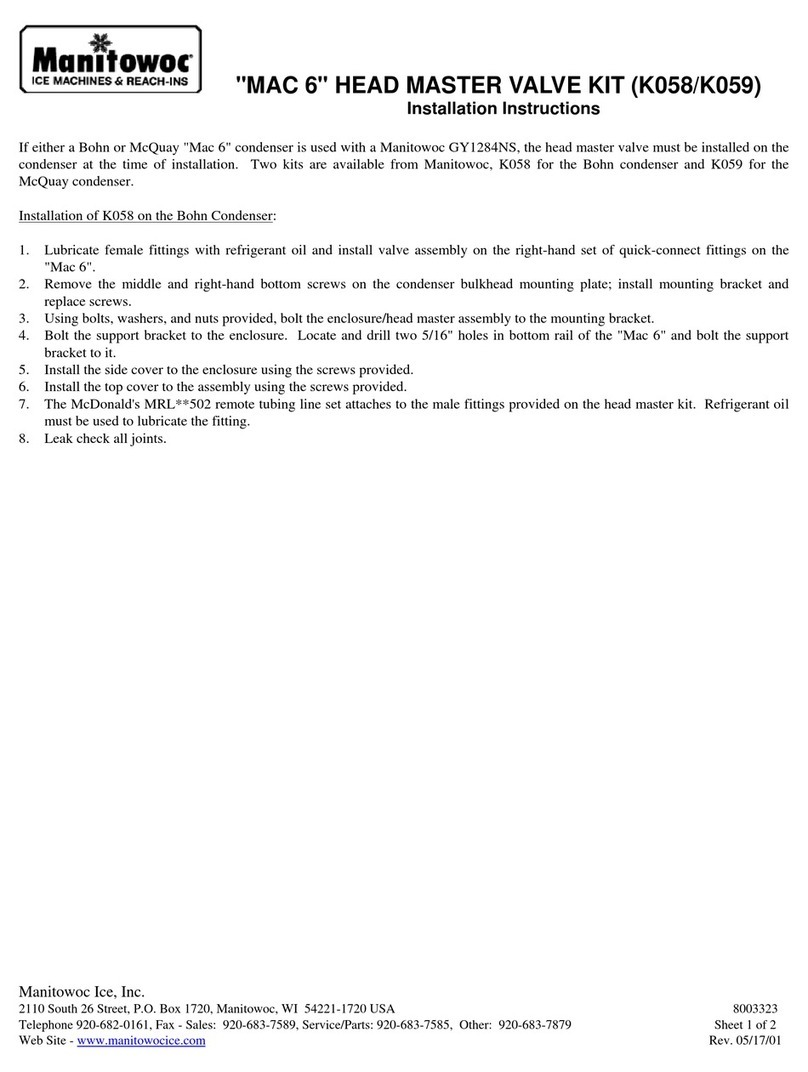
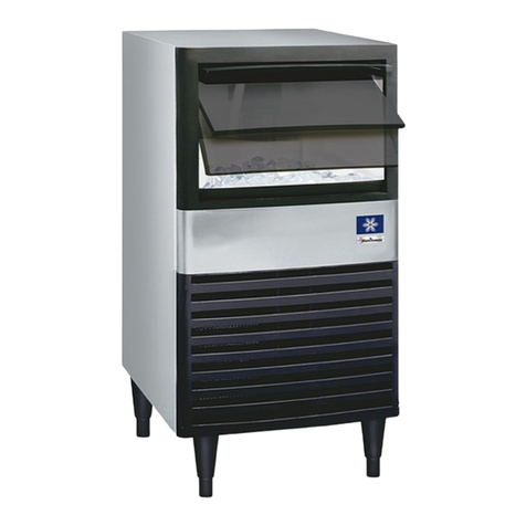
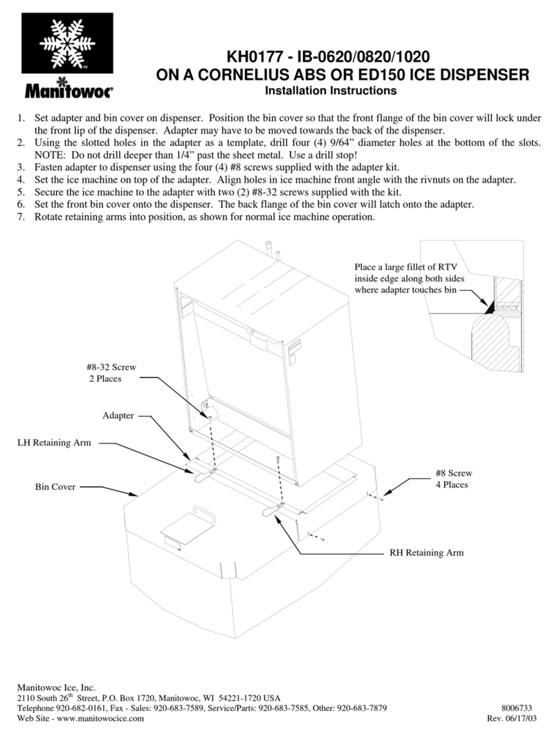
manuals.online logo
Brands
  1. Home
  2. •
  3. Brands
  4. •
  5. Manitowoc
  6. •
  7. Ice Maker
  8. •
  9. Manitowoc K00459 User manual

Manitowoc K00459 User manual

Instruction Sheet Subject: K00459 - S Model Bin Thermostat Kit
ICE MACHINE ON COKE FREESTYLE DISPENSER W/ADAPTER
KIT
®
1 of 4
Document Number: 000013527 Rev01 01/16
MANITOWOC FOODSERVICE  ICE MACHINE DIVISION
2110 SOUTH 26TH STREET, MANITOWOC, WI 54220
844724CARE
WWW.MANITOWOCICE.COM
Warning
Authorized Service Representatives are obligated to
follow industry standard safety procedures, including,
but not limited to, local/national regulations for
disconnection / lock out / tag out procedures for all
utilities including electric, gas, water and steam.
Warning
Disconnect electric power to the ice machine and
dispenser at the electric switch box before proceeding.
DANGER
Failure to disconnect the power at the main power supply
disconnect could result in serious injury or death. The
power switch DOES NOT disconnect all incoming power .
Two or more people are required to move this equipment
to prevent tipping..
Warning
Two or more people are required to move this
equipment to prevent tipping..
1. Move the ice machine and dispenser away from the
wall for easier access.
2. Bracket selection
A. Dual evaporator ice machines - Use bracket with
the shorter top flange.
B. Single evaporator ice machines - Use bracket with
the longer top flange.
3. Remove all panels and control box cover from the ice
machine.
4. If an ice machine is already installed on the dispenser:
• Remove the fasteners securing the ice machine to the
adapter (located on the rear of the dispenser).
• Raise and support the installation side of the ice
machine.
5. Hook the bracket assembly onto the respective back
spacer flange. Locate bracket assembly as illustrated.
NOTE: Dimension is from the edge of the adapter to the
edge of the bracket.
Single evaporator – 23.00” from right side of adapter.
Dual evaporator – 18.00”from right side of adapter
6. Lower/place ice machine on dispenser and secure ice
machine to adapter with fasteners. It is important to
confirm that the ice maker is slid rearward contacting
the bracket and back spacer flange before re-fastening
(close gap).
23”
Use long ange bracket
Conrm presence of back
spacer ange fastened to
adapter and ice maker
18”
Use short ange bracket
Conrm presence of back spacer
ange & vertical bracket fastened
to adapter and ice maker
2 of 4
Document Number: 000013527 Rev01 01/16
Subject: K00459 S Model Bin Thermostat
®
7. Route thermistor wire out towards the back of the
dispenser (lower the ice machine, if supported).
Remove unused 7/8”diameter knockout on the back
panel, snap fit the bushing over the exposed panel
hole, and route wire into the ice machine control board
compartment. Internally the cable must be routed as
to avoid contact with high voltage, high heat, or sharp
objects.
8. Normally the controller can be mounted on the
bulkhead flange. If not, a suitable area must be found
for your model. Use controller bracket to locate
mounting holes on the flange of the bulkhead. Drill
two 9/32” diameter holes. Do not mount the controller,
at this time.
9. Route the four wires from the temperature control to
the control box (insuring that the wires will not come
in contact with any refrigeration tubing).
Caution
The thermostat must be wired to match the voltage of
the ice machine. The thermostat is factory wired for 115
volts. Rewire thermostat, if your ice machine is 240 volts.
10. The control box line voltage wiring offers two options:
• Connect thermostat L1 (brown) and L2 (blue)
wires to contactor (incoming line voltage side)
L1 and L2.
OR
• Disconnect incoming power line wire nuts.
Remove quick-connect fittings from brown and
blue wires and strip 1/2”of insulation from the
wires. Connect incoming power L1, ice machine
L1, and thermostat L1 (brown) wires together
with wire nut. Connect incoming power L2, ice
machine L2, and thermostat L2 (blue) wires
together with wire nut..
11. Connect bin switch wires:
Manitowoc Models
A. Disconnect the red male/female connector bin
switch wire and connect the red male wire from
the controller to the red female bin switch wire.
B. Connect the white male bin switch wire to the
white female wire of the controller.
KoolAire Models
A. Cut the red bin switch wire 3 inches from molex
connector on bin switch.
B. Strip wires and install male and female crimp
connectors supplied in kit.
C. Connect male and female connectors from the bin
thermostat into the newly installed terminals.
12. Restore all power to the ice machine and dispenser at
the service-disconnect or fuse/breaker panel.
13. The factory setting on the thermostat will be correct for
most applications. Adjust only when necessary.
14. With two screws, secure the controller bracket
assembly to the flange of the bulkhead.
15. Reinstall the control box cover and all panels.
®
3 of 4
Document Number: 000013527 Rev01 01/16
Subject: K00459 S Model Bin Thermostat
CONTROLLER WIRING
CONTROL SETTINGS
The controller has a one-minute time delay anytime power
is interrupted and restored.
TOUCH PAD LOCK
P5 Jumper
The P5 jumper position determines if the touch pad is
locked or unlocked. The control is factory locked; to unlock,
move the jumper from one pin to two pins.
SETTING CONTROL SET POINT VALUE
To program the thermostat, plug the120V power cord into
an outlet and follow the steps below to program the Ice
Thermostat, plug the120V power cord into an outlet and
follow the steps below.
1. The thermostat set point is to be set at 38° Fahrenheit
with a 2° differential.
2. Setting the Set Point to 38°F
A. Press and hold the Menu button until the display
changes to flashing “SP”. This will take about 2
seconds.
B. Press the Menu button again. The current set point
is displayed.
C. Press the Up or Down button to adjust the set
point temperature.
D. Press the Menu button to save. The display then
returns to the sensor temperature.
3. Setting the Differential at 2°
A. Press and hold the Menu button until the display
changes to flashing “SP”. This will take about 2
seconds.
B. Press the Up or Down button until the“DIF”
function is displayed.
C. Press the Menu button to display the function’s
current value.
D. Press the Up or Down button until the desired
value is displayed.
E. Press the Menu button to save the new value. The
display then returns to the sensor temperature.
115V
240V COM NC NOC
P5 P4
Red Sensor Lead
Black Sensor Lead Text
Match Wiring
To Ice Machine
Voltage Bin Switch
Or
Toggle Switch
Connections
4 of 4
Document Number: 000013527 Rev01 01/16
Subject: K00459 S Model Bin Thermostat
®
CHECK PROCEDURE
If the control system does not function properly, verify that
the control is wired and set up properly. If the problem
persists, use the following procedures to determine the
cause of the problem.
Warning
Line voltage is present inside the control. Contact with
line voltage can cause injury or death
Follow these troubleshooting procedures in the order
presented. Do not skip any of the steps in the procedures.
1. Check for proper voltage to the control.
A. Remove the cover by loosening the four cover
screws.
B. Use an AC voltmeter to check the voltage between
the common and 120V or 240V terminals.
C. The voltage must be between 102 and 132 volts for
120V applications; 177 and 264 volts for 208/230V
applications.
D. If the voltage reading is not within the required
range, check the power source and input power
wires for problems.
2. Check for Fault Codes
If the LCD displays an alarm or fault code (SF or EE):
Fault Code Definition Solution
SF flashing
alternately with OP
Open temperature
sensor or sensor
wiring
See Step 3. Cycle
power to reset
control
SF flashing
alternately with SH
Shorted temperature
sensor or sensor
wiring
See Step 3. Cycle
power to reset
control
EE Program failure Reset the control
by pressing MENU.
If problem persists
replace the control,
3. Check for proper operation.
Important
Perform Steps 1 and 2 before performing these steps:
A. Disconnect the load from the output relay
terminals.
B. Reconnect the sensor leads and supply power to
the control.
C. Replace the cover.
D. Check the control settings for proper values.
E. Press and hold MENU until SP appears.
F. Press up and down (arrows) to change the set
point temperature above and below the sensor
temperature until the relay energizes and de-
energizes.
G. If the output relay does not perform as indicated,
replace the control.
H. If proper operation of the control is verified,
reconnect the load.

Other Manitowoc Ice Maker manuals

Manitowoc QM 20 User manual

Manitowoc

Manitowoc QM 20 User manual

Manitowoc S1000M User manual

Manitowoc

Manitowoc S1000M User manual

Manitowoc S model Instructions for use

Manitowoc

Manitowoc S model Instructions for use

Manitowoc Indigo Series User manual

Manitowoc

Manitowoc Indigo Series User manual

Manitowoc S model Instructions for use

Manitowoc

Manitowoc S model Instructions for use

Manitowoc CNF Series User manual

Manitowoc

Manitowoc CNF Series User manual

Manitowoc SF0406A Instructions for use

Manitowoc

Manitowoc SF0406A Instructions for use

Manitowoc Indigo I1200 User manual

Manitowoc

Manitowoc Indigo I1200 User manual

Manitowoc Q460 Instruction and safety manual

Manitowoc

Manitowoc Q460 Instruction and safety manual

Manitowoc LB User manual

Manitowoc

Manitowoc LB User manual

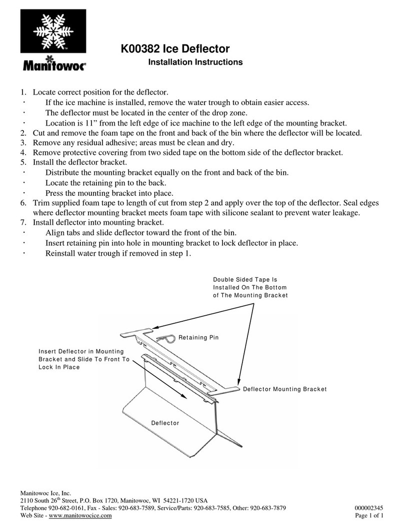
Manitowoc ICE DEFLECTOR K00382 User manual

Manitowoc

Manitowoc ICE DEFLECTOR K00382 User manual

Manitowoc 30" Q-MODEL ICE MACHINES MYLAR STRIP 7600153 User manual

Manitowoc

Manitowoc 30" Q-MODEL ICE MACHINES MYLAR STRIP 7600153 User manual

Manitowoc QuietQube Indigo Series User manual

Manitowoc

Manitowoc QuietQube Indigo Series User manual

Manitowoc RNS0244 User manual

Manitowoc

Manitowoc RNS0244 User manual

Manitowoc Q130 series Instructions for use

Manitowoc

Manitowoc Q130 series Instructions for use

Manitowoc Indigo NXT User manual

Manitowoc

Manitowoc Indigo NXT User manual

Manitowoc QM45 Series Guide

Manitowoc

Manitowoc QM45 Series Guide

Manitowoc QM30A Owner's manual

Manitowoc

Manitowoc QM30A Owner's manual

Manitowoc IT1900 User manual

Manitowoc

Manitowoc IT1900 User manual

Manitowoc S600M Instruction and safety manual

Manitowoc

Manitowoc S600M Instruction and safety manual

Manitowoc QM30 Series User manual

Manitowoc

Manitowoc QM30 Series User manual

Manitowoc UG Series User manual

Manitowoc

Manitowoc UG Series User manual

Manitowoc CSA-151 series Instruction Manual

Manitowoc

Manitowoc CSA-151 series Instruction Manual

Manitowoc MARINE MODEL S1800 User manual

Manitowoc

Manitowoc MARINE MODEL S1800 User manual

Popular Ice Maker manuals by other brands

Rosewill RHIM-15001 user manual

Rosewill

Rosewill RHIM-15001 user manual

Follett Horizon Chewblet 1810 Series installation instructions

Follett

Follett Horizon Chewblet 1810 Series installation instructions

Frigidaire EFIC108-C user manual

Frigidaire

Frigidaire EFIC108-C user manual

Black & Decker BIMH326S instruction manual

Black & Decker

Black & Decker BIMH326S instruction manual

Scotsman ID150 Service manual

Scotsman

Scotsman ID150 Service manual

Electrolux EI15IM55GS - 15 Inch Ice Maker Specifications

Electrolux

Electrolux EI15IM55GS - 15 Inch Ice Maker Specifications

Whirlpool ECKMF94 - Automatic Ice Maker installation guide

Whirlpool

Whirlpool ECKMF94 - Automatic Ice Maker installation guide

Hoshizaki KML-450MAF parts list

Hoshizaki

Hoshizaki KML-450MAF parts list

Hoshizaki F-1100MWA parts list

Hoshizaki

Hoshizaki F-1100MWA parts list

Barton 94024 Owner's manual and safety instructions

Barton

Barton 94024 Owner's manual and safety instructions

EdgeStar IP220SS owner's manual

EdgeStar

EdgeStar IP220SS owner's manual

CombiSteel 7453 Series Cleaning and sanitizing manual

CombiSteel

CombiSteel 7453 Series Cleaning and sanitizing manual

Danby Designer Ice'n Easy DIM1524W owner's manual

Danby

Danby Designer Ice'n Easy DIM1524W owner's manual

Follett U300 Series Operation manual

Follett

Follett U300 Series Operation manual

Vivax IM-122T user manual

Vivax

Vivax IM-122T user manual

Hoshizaki KM-2000SRE3 Final Parts List

Hoshizaki

Hoshizaki KM-2000SRE3 Final Parts List

Hoshizaki F-800MAF parts list

Hoshizaki

Hoshizaki F-800MAF parts list

Melchioni Ice Maker user manual

Melchioni

Melchioni Ice Maker user manual

manuals.online logo
manuals.online logoBrands
  • About & Mission
  • Contact us
  • Privacy Policy
  • Terms and Conditions

Copyright 2025 Manuals.Online. All Rights Reserved.