Manta 5 HYDROFOILER XE-1 User manual

1 | AS00009 REV 1 MANTA5 XE-1 INITIAL ASSEMBLY GUIDE
ENGLISH - ORIGINAL INSTRUCTIONS:
This manual was drafted in English language and may have been translated
into other languages (Translation of the original instructions) accompanying the original instructions.
AS00009 REV 2 MANTA5 XE-1 INITIAL ASSEMBLY GUIDE


WE ENCOURAGE YOU TO VISIT OUR WEB SITE WWW.MANTA5.COM FOR A DIGITAL VERSION OF THIS
MANUAL AND UPDATED TECHNICAL SUPPORT INFORMATION.
WARNING
USE OF THIS PRODUCT AND PARTICIPATION IN THE SPORT INVOLVES INHERENT RISKS OF INJURY OR DEATH.
TO REDUCE RISKS:
• Ride in water conditions that do not exceed the skills of the rider.
• Riders should remain within reasonable swimming distance to shore at all times.
• Attempting to ride in rough water, or in waves can increase the risk of injury or death.
• Do not use in shallow water or near swimmers or other watercraft.
• Always wear a suitable personal floatation device that is approved by your relevant local regulating body .
• Riders are highly recommended to wear suitable aquatic footwear and swimwear to protect from potential
injury.
• Understand and abide by your local maritime regulations.
• When losing control of the bike, push off pedals to fall away from the bike.
• Children shall be a minimum of 16 years of age to operate the bike.
• Never ride after consuming drugs or alcohol.
• Never ride without a suitable communication device or supervision from the land.
• Read the User Manual before use.

TABLE OF CONTENTS
PART 1. INTRODUCTION 5
1.1 IMPORTANT SAFETY SYMBOLS AND WARNINGS .................................................................................................................................................................. 5
PART 2. PACKAGING CONTENTS 5
2.1 INTRODUCTION ................................................................................................................................................................................................................................. 5
2.2 UNPACKING AND CHECKING COMPONENTS ........................................................................................................................................................................... 5
2.3 HYDROFOILER XE-1 PARTS MAP & LIST ................................................................................................................................................................................... 6
PART 3. HYDROFOILER XE-1 PRE-ASSEMBLY 9
3.3.1 OVERVIEW ............................................................................................................................................................................................................................ 9
3.3.2 STABILISING YOUR HDYROFOILER XE-1 FOR ASSEMBLY .................................................................................................................................... 9
3.3.3 ATTACH THE HANDLEBARS & SEAT POST .................................................................................................................................................................. 9
3.3.4 RE-STABILISING THE HYDROFOILER XE-1 FOR ASSEMBLY ................................................................................................................................. 9
3.3.5 ASSEMBLE THE FRONT TILLER SECTION .................................................................................................................................................................. 9
3.3.6 ATTACH THE FRONT TILLER SECTION ....................................................................................................................................................................... 10
3.3.7 ATTACH THE REAR FOIL ................................................................................................................................................................................................. 10
3.3.8 UPRIGHTING THE HYDROFOILER XE-1 CAREFULLY RESTING ON ITS FOILS ................................................................................................ 10
3.3.9 ATTACH THE FRONT BUOYANCY MODULES ............................................................................................................................................................ 10
3.3.10 INSTALL THE PEDALS ..................................................................................................................................................................................................... 11
PART 4. BATTERY CONFIGURATION AND PAIRING 12
4.1 CHARGING THE BATTERY ............................................................................................................................................................................................................. 12
4.1.1 BATTERY REMOVAL ......................................................................................................................................................................................................... 12
4.1.2 BATTERY CHARGING PROCEDURE ............................................................................................................................................................................. 12
4.2 PAIRING GARMIN® EBIKE REMOTE .......................................................................................................................................................................................... 13
4.2.1 DEVICE OVERVIEW .......................................................................................................................................................................................................... 13
4.2.2 PAIRING THE REMOTE WITH YOUR HYDROFOILER XE-1 ................................................................................................................................... 13
4.2.3 GARMIN® EBIKE REMOTE LED STATUS .................................................................................................................................................................... 13
PART 5. INSTALL THE PROPELLER 14
PART 6. DISSASSEMBLY FOR TRANSPORT 14
6.2.1 DISCONNECT & REMOVE THE BATTERY ................................................................................................................................................................... 14
6.2.2 REMOVE THE PROPELLER ............................................................................................................................................................................................ 14
6.2.3 REMOVE FRONT TILLER ................................................................................................................................................................................................. 14
6.2.4 REMOVE THE REAR FOIL ............................................................................................................................................................................................... 14
6.2.5 IN-CAR TRANSPORTATION ........................................................................................................................................................................................... 15
5
PART 1. INTRODUCTION
This document provides information on the initial assembly of the Hydrofoiler
XE-1 upon receival. Initial assembly is required in order to prepare for transport
to your ride location.
More complete product information is located within the Hydrofoiler XE-1
Owners Manual document.
The following is the basic layout of this document in order to complete the initial
assembly of your Hydrofoiler XE-1:
1. Packaging contents and Hydrofoiler XE-1 parts list
2. Pre-assembly guide
3. Configuration and pairing
4. Diassembly for transport
Please note that Manta5 operates a policy of continuous improvement, all
manual contents are subject to change and update without notice.
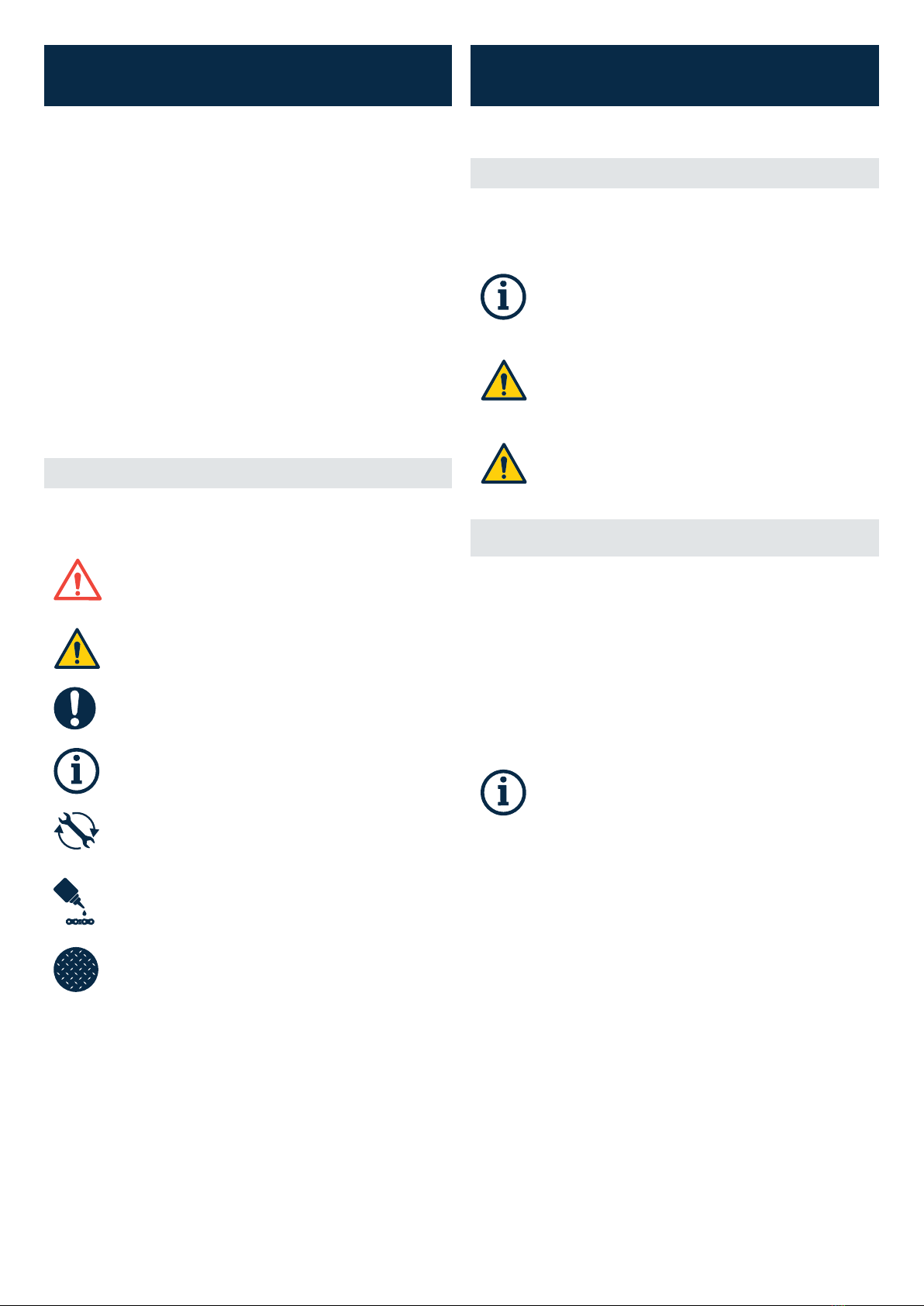
1.1 IMPORTANT SAFETY SYMBOLS AND WARNINGS
Your safety is important. When reading this manual you will find symbols and
warnings with information to help keep you safe.
WARNING! Warns of hazards which could result in personal
injury or threat to health, including potential danger zones in
which any exposed person (wholly or partially within) is subject
to a risk to their health or safety.
CAUTION: Indicates a potentially hazardous situation, which, if
not avoided, may result in risk to user health or safety or, is an
alert against unsafe practice.
NOTICE: Alert of information of particular importance which if
not adhered to could result in damage to your hydrofoiler or void
your warranty.
INFORMATION: Indicates information of particular importance,
or a tip noting key information to improve your experience with
your Hydrofoiler.
TORQUE: Indicates that a torque wrench or similar is
recommended to avoid fasteners either coming loose or being
overtightened.
LUBRICATE: Symbol indicates the specified lubricant should be
applied as instructed.
FRICTION PASTE: Symbol indicates friction paste should be
applied. Avoid lubricant here.
PART 2. PACKAGING CONTENTS
2 .1 INTRODUCTION
Your Hydrofoiler XE-1 arrives fitted with the motor, battery tray and battery as
well as the rear buoyancy modules.
INFORMATION: When assembling the Hydrofoiler XE-1,
Manta5 recommend using a friction paste for certain Hydrofoiler
components and a torque meter may also be required to ensure
the correct tightness of parts.
CAUTION: The Hydrofoiler is top-heavy when in the upside
down position so make sure the surface you are placing it on for
assembly (both initial and waterside) is flat and level.
CAUTION: Lifting the Hydrofoiler is easier with two people.
Never strain to lift, manoeuvre or handle the items or the
Hydrofoiler XE-1.
2.2 UNPACKING AND CHECKING COMPONENTS
Upon receiving your Hydrofoiler XE-1, check the outside of the packaging for
any damage. If any damage can be seen, it is best to stop at this point and
report the damage to both the shipping company and Manta5. If possible, take
a photograph of any damage for future reference.
The Hydrofoiler XE-1 is shipped in two boxes:
• The large box (bike box) contains the main bike frame and assembly
components.
• The small box (foil box) contains the foils (front and rear).
INFORMATION: When removing assembly parts from the bike
box, take care to remove the front tiller assembly from the
internal layer (situated underneath the propeller, pedals & seat).
Do NOT dispose without having opened and removing the front
tiller assembly.

6 | AS00009 REV 1 MANTA5 XE-1 INITIAL ASSEMBLY GUIDE
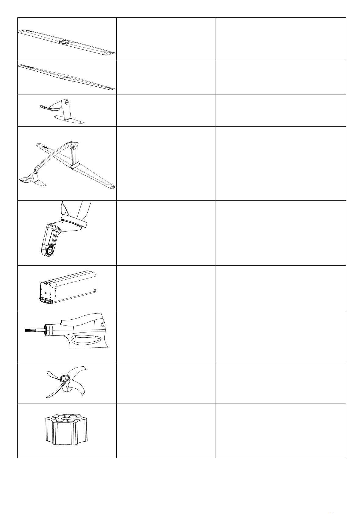
2.3 HYDROFOILER XE-1 PARTS MAP & LIST
Common Parts List:
IMAGE COMMON NAME PART NO
Front buoyancy modules BA00001 (RH)
BA00002 (LH)
Rear buoyancy modules BA00003 (RH)
BA00004 (LH)
Buoyancy clips - short BP00004 (Black)
Buoyancy clips - long BP00003
7
Rear foil WA00004
Front foil WA0003
Mini tiller WP00008, WP00009, WP00010, WP00011, WP00012
Front tiller assembly WA00005
Steering fork SA00001
Battery EA00001
Propeller drive shaft DA00005
Propeller DA00011
Hex block DP00030
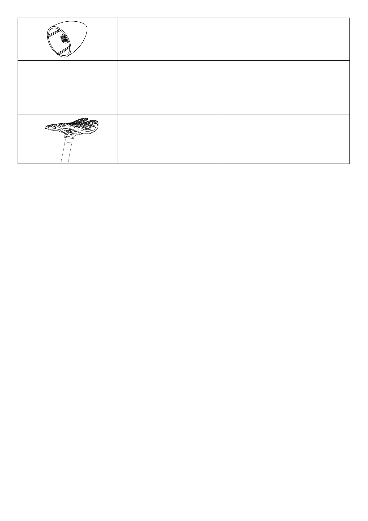
8 | AS00009 REV 1 MANTA5 XE-1 INITIAL ASSEMBLY GUIDE
Propeller nose cone DP00031
Grintech battery charger EA00049
Seat and seat post assembly HA00016

9
PART 3. HYDROFOILER XE-1 PRE-ASSEMBLY
3.3.1 OVERVIEW
CAUTION: The Hydrofoiler XE-1 contains some complex items
such as the battery, motor and gearboxes that shall not be
assembled/dismantled by the user. This initial assembly manual
is not intended as a fully comprehensive: use, assembly, service,
maintenance or repair guide. Where events uncover topics not
covered in the manuals then please contact Manta5.
CAUTION: Take care when lifting to avoid injury to yourself or
damage to the product.
3.3.2 STABILISING YOUR HDYROFOILER XE-1 FOR ASSEMBLY
a. Remove rear foil from foil box. Ensure that the rear foil is on a clear
and stable flat surface.
b. Lift the Hydrofoil bike out of the box and gently insert into the rear
foil shoe. This will provide the stability needed for handlebar and seat
post assembly.
3.3.3 ATTACH THE HANDLEBARS & SEAT POST
INFORMATION: Requires 4 mm hex key.
TORQUE: Manta5 recommends using a torque wrench to fasten
the stem to the steering tube. The specified torque is 3-4 Nm.
Take caution to not over-tighten the stem to the steering tube.
FRICTION PASTE (optional): Apply a light coating of friction
paste between the steering tube and the stem.
FRICTION PASTE (optional): Apply a light coating of friction
paste inside the frame where the seat tube inserts.
c. Slide the handlebars onto the steering tube and align so they are
square to the steering fork, tighten to 3 Nm. NOTE: You will be able
to adjust the angle of the handlebars more accurately later if needed.
d. Insert the seat post into the frame tube and secure with the seat-post
clamp. You can use a 5 mm hex wrench to adjust the pressure applied
by the clamp if necessary.
3.3.4 RE-STABILISING THE HYDROFOILER XE-1 FOR
ASSEMBLY
CAUTION: In the upside-down position, the Hydrofoiler XE-1 is
top-heavy. Make sure the floor you are placing it on is flat, level
and on a non-abbrasive surface to avoid any scratching to the
hydrofoil bike.
CAUTION: Lifting the Hydrofoiler is easier with two people.
Never strain to lift, manoeuvre or handle the items or the
Hydrofoiler XE-1.
NOTICE: Take care to place the Hydrofoiler XE-1 in a location
where it won’t be accidentally knocked over or blown over in
the wind.
e. Carefully lift the bike out of the box and place it upside-down resting
on the handlebars and seat, with the handlebars square to the frame
for best stability.
3.3.5 ASSEMBLE THE FRONT TILLER SECTION
1 Nylock nut, spacer, bolt
2 Front tiller arm
3 Front foil (located in foil box)
4 Mini tiller
1
2
3
4

10 | AS00009 REV 1 MANTA5 XE-1 INITIAL ASSEMBLY GUIDE
INFORMATION: Requires 4 mm & 5 mm hex key.
INFORMATION (optional): Apply Loctite to the screws prior
to installing them. This can be found at your local hardware
store.
f. Put the spacer through the hole in the mini tiller, align the mini tiller
section with the front of the tiller arm (the mini pivot junction). Put
the nylock nut into the hex side of the mini pivot junction and place
the mini tiller into the mini pivot junction (ensuring the spacer lines up
with the bolt hole and nut) before pushing the bolt through from the
other side. Use the 4 mm hex key to tighten the bolt into the nylock
nut.
g. Once complete, attach the front foil. Turn the front tiller arm upside
down, with the tiller arm and mini tiller facing forward. Remove the
two screws and washers from the front tiller shoe using the 4 mm
hex key. Next align the front foil to the front tiller shoe by having the
thicker end of the foil at the front and the thinner edge facing towards
yourself (logo facing downward).
h. Place a washer on each hole in the front foil, and place the screws
through the washers and holes, until they are lined up with the
threaded holes in the front tiller. Use the 4 mm hex key to tighten the
screws until they are firm. Once you have fully assembled the front
tiller section to check that the front foil has been correctly assembled,
stand behind the now upright tiller and ensure that the Manta5 logo
is facing you.
INFORMATION: The following process of attaching the
front tiller and rear foil to your Hydrofoiler XE-1 will provide
the stable platform you will need in order to attach the
front buoyancy modules and pedals, completing the initial
assembly. It is important to assembly your Hydrofoiler on a
flat, stable and non-abbrasive surface in order to complete
the next steps.
3.3.6 ATTACH THE FRONT TILLER SECTION
INFORMATION: Requires 5 mm hex key.
1. Assemble the front tiller to the steering fork assembly and fasten by
tightening the countersunk screw into the nylock nut.
3.3.7 ATTACH THE REAR FOIL
INFORMATION: Requires 6 mm hex key.
i. Holding the foil horizontal and upside-down, slide the bayonet shoe
onto the bayonet upright. NOTE: It will not fully assemble until the
captive screw is tightened using the 6 mm hex key.
j. Tighten the captive cap-screw, which secures the foil to the frame.
3.3.8 UPRIGHTING THE HYDROFOILER XE-1 CAREFULLY
RESTING ON ITS FOILS
NOTICE: The foil does not add much weight, but the
combination is now wider and more awkward to handle. When
turning over, be careful not to drop the foil on the ground and
watch for the front tiller dropping.
CAUTION: If in doubt, Manta5 recommend that the Hydrofoiler
XE-1 is lifted by two people.
a. Before turning over: ensure there is enough clear space to safely
rotate the bike onto.
b. Stepping from the front of the Hydrofoiler, hold both hand grips and
turn over, placing in the upright position resting on its foils. Ensure
the front foil is parallel to the ground with the mini-tiller hanging in
free-air.
c. Now that the rear foil is attached and the Hydrofoiler XE-1 is upright,
it is more stable and you can continue with the assembly.
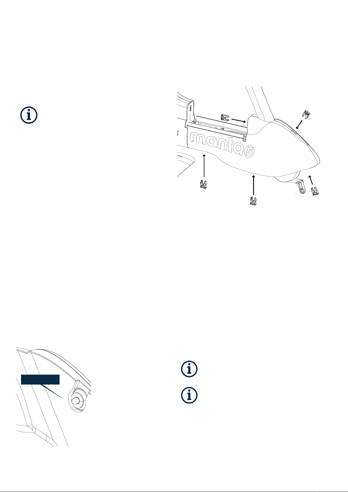
3.3.9 ATTACH THE FRONT BUOYANCY MODULES
11
INFORMATION: This step can be easier with two people. If
dropped onto a hard surface the buoyancy modules could be
damaged. It can be done with one person, but is much easier to
have a helping hand.
a. Slide the stirrup to the forward position.
b. Make sure you have x5 short buoyancy fastener clips (BP00004) to
hand.
c. Insert the RH Front buoyancy module first by seating the upper edge
under the lip of the battery tray. This is best done by pressing the rear
edge in first, and then the front edge.
d. Offer up the left hand front buoyancy module making sure to
engage the male bullet shape pin guide fasteners with their female
counterparts. This is easiest done by holding the lower edge outward
and again engaging the top edge of the buoyancy under the battery
tray lip. Push the buoyancy up while gently wiggling it until it locks
in place.
e. The two buoyancy modules will fit snugly around the shaped sections
of the frame.
f. While lifting the rearward side of the front buoyancy, reach through
the top of the battery tray and slide the stirrup backwards.
g. Place the x5 short buoyancy fastener clips (BP00004) into the slots to
lock both buoyancy modules in place.
h. If you are having difficulty with this, partially loosen the 4 cap screws
in the battery tray and re-insert the front buoyancy modules using
the same method, once the buoyancy clips have been installed then
re-tighten the battery tray screws.
3.3.10 INSTALL THE PEDALS
INFORMATION: Requires either a 6 mm hex key or a 15 mm
spanner.
INFORMATION: The pedals have ‘L’ and ‘R’ marked on them.
Ensure the L and R side pedals are assembled to the correct
side. The right-hand pedal has a right-hand thread (screw in
clockwise), and the left-hand pedal has a left-hand thread
(screw in anti-clockwise).
a. Screw in each pedal the correct direction of rotation while holding the
corresponding crank arm. You will need a tool that will provide at least
200 mm of leverage to tighten the pedals with sufficient torque (30
Nm.). A 15 mm spanner can be used across the flats of the pedal or
a 6 mm hex key can be passed through the hole in the crank arm and
used in the pedal hex recess.
b. After tightening, check that the pedals spin freely.
PING GUIDE FASTENER
(BP00002)
12 | AS00009 REV 1 MANTA5 XE-1 INITIAL ASSEMBLY GUIDE
CAUTION: Take care to ensure that the pedals are attached
tight enough to the cranks, Manta5 recommend a sufficient
torque of 30Nm. Failure to ensure this could result in the
pedals coming loose during your ride.
PART 4. BATTERY CONFIGURATION AND PAIRING
4 .1 CHARGING THE BATTERY
NOTICE: The battery should be re-charged once every 2 months
when it is not used. Negligence could lead to complete discharge
of the battery and would make the warranty on the battery void.
Manta5 will send your email reminders.
NOTICE: It is not recommended to have the battery pack
connected permanently to the charger.
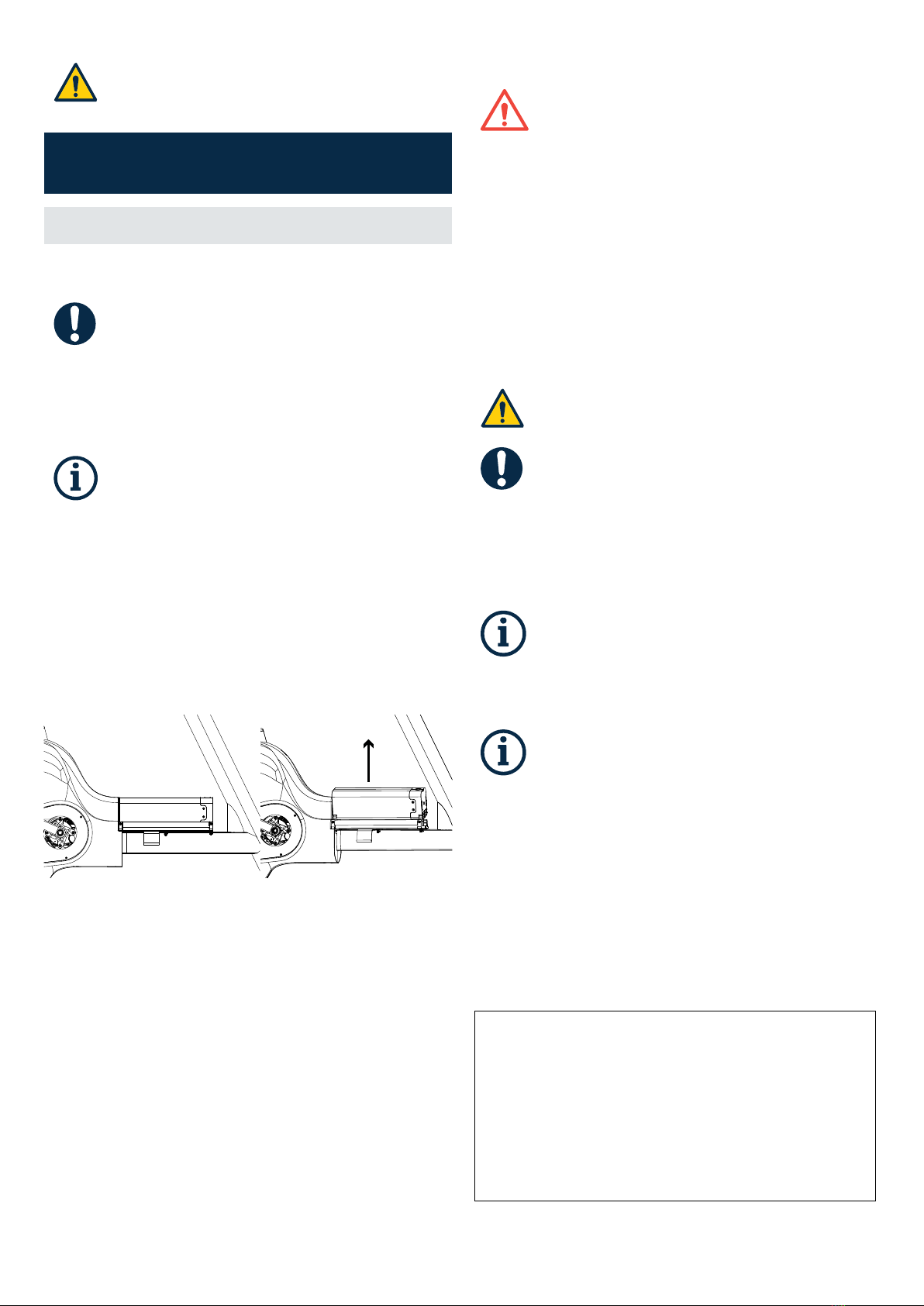
4.1.1 BATTERY REMOVAL
INFORMATION: Requires 4 mm hex key.
a. Make sure the battery is switched off by checking there is no
illuminated ring around the battery switch. Turn it on then off again
if you are unsure.
b. Remove the battery from your Hydrofoiler. First unfasten the battery
by unscrewing the two grub screws far enough not to impede the
removal of the battery but leaving the grub screws retained in the
battery tray.
c. Carefully remove the battery pack from the battery tray by tilting
the battery towards the two lugs on the left hand side of the tray to
disengage with the notches in the battery casing.
d. Should the battery be plugged in; disconnect the connector by twisting
the blue lock collar (anti-clockwise).
e. Fully remove the battery from the battery tray for charging.
4.1.2 BATTERY CHARGING PROCEDURE
WARNING! - RISK OF FIRE: Lithium-ion battery packs can be
dangerous if charged incorrectly. Use only the battery charger
supplied by Manta5 for charging the Hydrofoiler XE-1 lithium-
ion battery.
WARNING! - RISK OF FIRE: Do not use the Manta5 battery
charger with any other batteries.
WARNING! - RISK OF FIRE: Never connect the charger to an
unregulated generator.
WARNING! - RISK OF FIRE: Never let a battery be charged
unattended. The battery and charger can get hot while charging.
Do not charge near any sources of heat, humidity or flammable
materials and never cover the charger or battery with clothes
or other objects.
WARNING! - RISK OF FIRE: The battery will not charge if it is
0°C (32°F) or less and greater than 40°C (104°F).
CAUTION - RISK OF INJURY: Do not allow children to handle the
battery or charger.
NOTICE: Charge the battery in a cool, dry, well-ventilated
location on a non-flammable surface. Do not charge the battery
in wet, high-temperature or high-humidity environments. This
means out of direct sunlight, and away from bath/shower-
rooms and similar.
NOTICE: If the battery is to be stored, then the battery should
be charged to 50% before storage, and stored in a room with a
working smoke detector. Use the store charge profile on your
charger.
INFORMATION: When you first receive your Hydrofoiler, the
battery will be partially charged. To get the best life out of your
battery; ensure to charge to full capacity before using for the
first time. For charging the battery pack, read and observe
the operating instructions of the charger. The battery can be
charged to/from any level of charge. Interrupting the charging
process does not damage the battery pack.
INFORMATION: Always remove the battery from the bike when
charging. Make sure the battery is dry and has cooled down
after use.
CHARGING PROCEDURE
a. Make sure the battery is powered OFF (There should not be illuminated
ring around the switch).
b. Connect the battery charger input lead to an AC mains power socket
with the power switch off. Do not use an extension cable.
c. Connect the battery charger to the battery by pushing the blue
connector into the battery socket. Press the plug in firmly until you
hear and/or feel the blue lock collar click indicating that the plug is
fully engaged, it clicks into place and the red dot becomes obscured.
d. Check to ensure the red dot is not visible.
e. Switch ON the power at the AC mains power socket - or omit this step
if you socket does not have a switch.

13
f. Turn on the battery and charging will commence. The battery switch
LED will illuminate according to the state of charge with a flashing
pulse, indicating the battery is charging.
g. Standard charge takes 4 hours for the battery to be fully charged.
Charging is complete when the battery switch LED turns solid green.
h. To abort charging, hold down the top button until “Abort Charge” is
displayed on the screen, then release the button.
i. Switch the battery off.
j. Unplug the battery from the charger.
k. Switch the charger off at the wall.
CHANGING CHARGING PROFILES
To change the charge profile from the recommended default
setting given, the user must select the appropriate charge rate.
Please note, fast charging in warmer ambient temperatures can
cause the battery to overheat and stall the recharge process.
Select the charging profile and hold down the bottom button
until the “Hold to Start” text at the bottom of the display
changes to “Okay”, release the button.
1. Fast Charge - 3hrs
2. Standard Charge (Default) - 4hrs
3. Slow Charge -5.7 hrs
4. Store Charge (For storing over long periods) - 2hours
CHARGE MODE CHARGER DISPLAY
FAST CHARGE
STANDARD CHARGE
(DEFAULT)
SLOW CHARGE
STORE CHARGE
NOTICE: Refer to storage in Owners Manual PART 4
TRANSPORTATION AND HANDLING
Store the battery in a cool, dry environment as per the battery storage instructions.
4.2 PAIRING GARMIN® EBIKE REMOTE
4.2.1 DEVICE OVERVIEW
1 Select to increase the motor
assist level.
2 Select to decrease the assist
level.
Hold to turn off the motor assist.
3 Status LED.
4.2.2 PAIRING THE REMOTE WITH YOUR HYDROFOILER XE-1
The first time you connect the GARMIN® eBike remote to your compatible
eBike, you must pair the remote with your XE-1.
a. Bring the remote within 1 m (3 ft.) of the battery.
NOTE: You must stay 10 m (33 ft.) away from other ANT+’” sensors while
pairing.
b. Turn the battery on.
c. On the GARMIN® eBike remote, hold two keys simultaneously until
the status LED starts alternating green and red, and release the keys.
The remote searches for your Hydrofoiler XE-1. After the remote pairs
successfully, the status LED flashes green 6 times. After the remote is paired, it
connects to your XE-1 whenever it is in range and turned on. You may need to
wake the remote by selecting any key.
4.2.3 GARMIN® EBIKE REMOTE LED STATUS
The green LED flashes one time when you select a key.
LED ACTIVITY STATUS
Flashing green The remote is searching for a paired
eBike.
Alternating red and green The remote is attempting to pair with
an eBike.
6 rapid green flashes The remote success fully paired with
an eBike.
Solid red Pairing has failed or the connection
was lost.
1 red flash every 5 seconds The remote has a low battery.
2 red flash every 5 seconds The eBike has a low battery.
3 red flash every 5 seconds The eBike has an error message.
Congratulations you have now completed the inital assembly of your Hydrofoiler
XE-1. You can now dissassemble the bike into the transportation configuration
(approx. 3 mins to complete).
1
2
3
14 | AS00009 REV 1 MANTA5 XE-1 INITIAL ASSEMBLY GUIDE
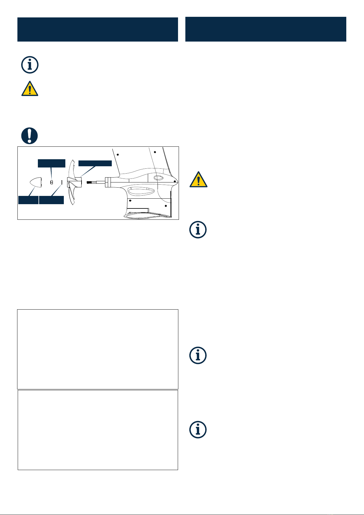
PART 5. INSTALL THE PROPELLER
INFORMATION: Requires 17 mm spanner.
CAUTION: Propellers by nature can contain sharp edges or
corners. Take care to avoid sharp parts when handling the
propeller. If in doubt, use a suitable glove.
CAUTION: Take care to avoid transporting the Hydrofoiler
XE-1 with the propeller fitted - unless the bike is at the riding
location and has been assembled ready for final transport to
the water.
NOTICE: If you are not ready to use the Hydrofoiler, then this
step could be addressed at a later date.
NOSE CONE
(DP00031)
NYLOC NUT
(HP00063 M10)
WASHER
(HP00050 M10)
PROPELLER (DP00032)
1. The propeller will have the ‘flanged bushings’ and hex block press-
fitted in. Please check to ensure that these parts are present before
attaching the propeller to the hydrofoil bike.
2. Checking the propeller orientation (hex recess at front), slide it onto
the propeller shaft.
3. Slide the hex block onto the shaft and ensure it locates both; inside the
hex recess of the propeller, and the hex on the propeller shaft.
4. Install the washer and nut onto the shaft. Take care to hold the
propeller of any sharp edges or corners, and use a 17mm spanner to
tighten the nut.
5. Gently screw the nose cone on hand tight - take care not to over-
tighten.
PART 6. DISSASSEMBLY FOR TRANSPORT
The Hydrofoiler XE-1 is modular to enable easy transportation. When
transporting the Hydrofoiler XE-1 there are items that will need to be removed
to enable safe and easy transportation. These items are detailed below:
6.2.1 DISCONNECT & REMOVE THE BATTERY
a. Using a 4 mm hex key undo the 2 grub screws that are securing the
battery in the battery tray.
b. Once loosened, lift the battery out of the tray and disconnect from the
Hydrofoiler connector cable.
c. Place battery down on a soft surface out of direct sunlight or store
away. For storage insctructions please REFER TO OWNERS MANUAL
SECTION 4.5.5 HYDROFOILER XE-1 BATTERY STORAGE.
6.2.2 REMOVE THE PROPELLER
CAUTION - RISK OF INJURY: It is essential that the propeller
is removed while the hydrofoil bike is in transit. This reduces
the risk of injury or damage to the product. Always handle the
propeller with care and stow it safely.
CAUTION - RISK OF INJURY: Propellers can contain sharp edges
and vertices. Take care handling the propeller not to touch sharp
features.
INFORMATION: Requires 17 mm spanner.
a. Unscrew by hand (turn anti-clockwise) the nose cone piece from the
front of the propeller.
b. Using a 17 mm spanner remove the nut and washer. Take care to hold
the propeller whilst avoiding any sharp edges or corners.
c. Slide propeller with the hex block off the propeller shaft. Take care not
to dislodge the flanged bushings.
d. Store all propeller assembly parts together to avoid losing any
components.
6.2.3 REMOVE FRONT TILLER
The front tiller assembly should always be removed for transport.
INFORMATION: Requires 5 mm hex key.
a. Remove the front tiller assembly by loosening the countersunk screw
from the nylock nut and removing the front tiller from the steering
fork assembly.
6.2.4 REMOVE THE REAR FOIL
INFORMATION: Requires 6 mm hex key.
a. Using a 6 mm hex key, loosen (turn anti-clockwise) the captive cap-
screw in the metal shoe which secures the rear foil to the frame.
b. The foil and shoe assembly will slide forward and can be removed as
the captive screw is loosened.
c. Place the foil down on a grass surface or surface free of debris that
could scratch or damage your foil.

6.2.5 IN-CAR TRANSPORTATION
For in-car transportation please go to HYDROFOILER XE-1 OWNERS MANUAL
SECTION 2.6 TRANSPORTATION AND HANDLING.

WWW.MANTA5.COM
Other manuals for HYDROFOILER XE-1
8
Table of contents


