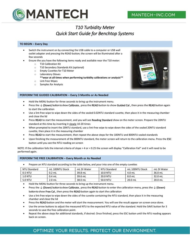
Mantech T10 User manual


In no event will the manufacturer be liable for direct, indirect, special, incidental or consequential damages
resulting from any defect or omission in this manual.
The manufacturer reserves the right to make changes in this manual and the products it describes at any time,
without notice or obligation.
The manufacturer is not responsible for any damages due to misapplication or misuse of this product including,
without limitation, direct, incidental and consequential damages, and disclaims such damages to the full extent
permitted under applicable law. The user is solely responsible to identify critical application risks and install
appropriate mechanisms to protect processes during a possible equipment malfunction.
Please read this entire manual before unpacking, setting up or operating this equipment. Pay attention to all
danger and caution statements.
Failure to do so could result in serious injury to the operator or damage to the equipment.
Make sure that the protection provided by this equipment is not impaired. Do not use or install this equipment
in any manner other than specified in this manual.

1. Technical Specifications.......................................................................................................................................................................4
2. Installation...........................................................................................................................................................................................5
2.1 Benchtop Setup...................................................................................................................................................................................5
2.2 Portable Setup.....................................................................................................................................................................................5
3. User Interface and Navigation.............................................................................................................................................................6
3.1 Interface Description...........................................................................................................................................................................6
3.2 Menu Navigation.................................................................................................................................................................................6
4. Calibration ...........................................................................................................................................................................................9
4.1 Guided Calibration...............................................................................................................................................................................9
4.2 Free Calibration.................................................................................................................................................................................13
5. Operation ..........................................................................................................................................................................................16
5.1 Power On/OFF...................................................................................................................................................................................16
5.2 Operation with Benchtop or Portable setup .....................................................................................................................................16
5.3 Operation with Automated Setup.....................................................................................................................................................18
6. Configuration.....................................................................................................................................................................................19
6.1 Time/Date .........................................................................................................................................................................................19
6.2 Display...............................................................................................................................................................................................19
6.2.1 Contrast.....................................................................................................................................................................................19
6.2.2 Backlight Time...........................................................................................................................................................................19
6.2.3 Backlight Level...........................................................................................................................................................................19
6.2.4 Partial Results............................................................................................................................................................................20
6.2.5 Big Number ...............................................................................................................................................................................20
6.3 Instrument.........................................................................................................................................................................................20
6.3.1 Auto-Off ....................................................................................................................................................................................20
6.3.2 Auto-Reading ............................................................................................................................................................................20
6.3.3 Color Compensation..................................................................................................................................................................21
6.3.4 Test Curves................................................................................................................................................................................21
6.3.5 Measuring Mode.......................................................................................................................................................................21
6.3.6 Sample ......................................................................................................................................................................................22
6.3.7 ID...............................................................................................................................................................................................22
6.3.8 Schedule Calibration .................................................................................................................................................................23
6.3.9 Calibration Check ......................................................................................................................................................................23
6.3.10 Customize................................................................................................................................................................................23
6.3.11 Tag Number.............................................................................................................................................................................23
6.3.12 Language.................................................................................................................................................................................23
6.4 Communication.................................................................................................................................................................................24
6.4.1 Eco Result..................................................................................................................................................................................24
6.4.2 Log Transmit..............................................................................................................................................................................24
6.4.3 Serial Baud ................................................................................................................................................................................24
6.4.4 Header.......................................................................................................................................................................................25
6.4.5 CSV Separator ...........................................................................................................................................................................25
6.4.6 Serial Communication...............................................................................................................................................................25
6.5 User Test ...........................................................................................................................................................................................25
6.6 Security..............................................................................................................................................................................................26
7. Replacement Parts, Accessories and Consumables...........................................................................................................................26
Appendix 1 –Warranty..........................................................................................................................................................................27
Warranty .................................................................................................................................................................................................27
Change to Specifications .........................................................................................................................................................................28
Liability....................................................................................................................................................................................................28

Measurement method
Ratio determination using a primary nephelometric light scatter signal (90°)
to the transmitted light scatter signal.
Reading units
NTU/ EBC
Lamp Source
Tungsten Lamp (White Light); LED Lamp (IR Light)
Method Conformity
EPA 180.1, ASTM D1889, SM 2130B (White Light);
ISO 7027 and EN27027 (IR Light)
Detector
Silicon Photocell
Measuring Range
0 to 1000 NTU / 0 to 250 EBC
Resolution
0.01 on lowest range
Accuracy
± 2% of reading: 0 to 1000 NTU
Repeatability
± 1% of reading or 0.01 NTU
Automatic Reading
With user-defined intervals 0 to 250 seconds
Maximum uncertainty
± 2% of full scale
Display
LCD 2 lines / 16 characters
Response Time
Programmable 6 to 41 sec
Data Logger
Up to 1000 data
Auto ShutOff
Programmable from 1 to 60 min
Fast Cal function
Quick Calibration for single point
Software Functions
Signal averaging, "Fast Settling", results freezing, analyst and sample
identification, calibration status, verification and calibration reminder,
calibration history, password
Sample Required
15 ml vial with lid
Sample vials
Round borosilicate glass vial with screw and caps (Φ = 24,5 mm)
Power Supply
4 AA batteries or USB power supply cable
Indicator
Low battery indicator / battery exchange
Serial Output
USB
Storage Conditions
0 to 40°C (instrument only)
Dimensions
114 x 198 x 83 mm

1. Set the meter on a flat, clean surface.
2. Plug the meter into a wall outlet using the provided USB
cable and a USB power adapter. Depending on country, a USB
power adapter may be provided as well.
3. Alternatively, plug the meter into a computer USB outlet.
1. With a Philips-head screw driver, remove the battery cover on the rear of the meter.
2. Install x4 AA batteries in the compartment, matching the orientation of the batteries to the diagram
below.
3. Replace the battery cover, ensuring the screws are tight.
4. Place the meter face-up in the provided carry case.

To access the instrument menu, hold the MENU key for 3 seconds. The T10 instrument menu is divided into 4
main functions with sub-menus:
•ID –Access the user ID functions
•Calibrate –Access the calibration functions
•Config –Access the configuration functions
•Service –Access the service functions (only for certified technicians)
When in the instrument menu, use the ↑ and ↓ keys to select the desired function, then press READ to enter it.
You can move back up a level in the menu structure using the ESC key, or by navigating to the ‘BACK’ option
displayed in many of the menu levels and pressing READ.
When typing out letters or numbers, use the ↑ and ↓ keys to scroll through letters/numbers, the MENU key to
move the cursor to the right, and the READ key to move the cursor to the left. Press ESC to erase an entered
number or letter.
To save any settings, options, or entered numbers/letters, hold the SAVE key for 3 seconds.
1. DISPLAY: Displays readings, diagnostics, and
operational data
2. ↑: Scrolls through menus, enters numbers
and letters
3. MENU: Selects options to configure the
instrument, selects analysis and moves the cursor
to the right
4. SAVE: Store selections and data, saves the
result to be USB transferred and selects the
parameters
5. ↓: Scrolls through menus, enters numbers
and letters
6. READ/ON: Switches the instrument on,
confirms options, sample reading, moves the
cursor to the left
7. ESC/OFF: Powers the instrument off (3 sec
hold), aborts operations, returns to the previous
screen

The full menu structure is listed below, with descriptions:
•ID –Access the user ID functions
oSample
oUser
•Calibrate –Access the calibration functions
oGuided Cal
oFree Cal
•Config –Access the configuration functions
oTime/Date –Update the date and time
▪Time
▪Date
oDisplay –Change the display settings
▪Contrast
▪Backlight Time
▪Backlight Level
oInstrument –Access the instrument configuration options
▪Auto Off
▪Auto Reading
▪Color Compensation
▪Hab. Tests
▪Fast Settling
▪Sample
▪ID
•User ID
•Sample ID
▪Schedule Cal
•F Scale
▪Instrument ID
▪Part Number
▪Language
•US
•ES
•BR
oCommunication –Communication configuration options
▪Eco Result
•New Mark
•All Mark
•New
•All
▪Log Transmit
•New Mark
•All Mark
•New
•All

Continued from previous page…
•Config –Access the configuration functions
oUser Test –Not applicable
▪User Test 1
▪User Test 2
oSecurity –Set the security levels for each menu option
▪ID
•Security Level
•Password
▪Calibration
•Security Level
•Password
▪Config
•Security Level
•Password
▪Service
•Security Level
•Password
•Service –Access the service functions (only for certified technicians)
oDatalog
▪Visualize
▪Log Transmit
oDiagnostic
▪Signal
▪Sensor
▪Battery
▪Duty
▪Current (mA)
▪Light
▪Temperature
▪Blank
▪NL Blank
▪F Scale
▪NL F Scale
▪Readings
oReset Calibration
oDefault
▪Activate Default
▪Save Default
oLight Calibration
oSet Time
oRecover Password

The T10 Turbidimeter is programmed with two internal calibration options:
•Guided Calibration
•Free Calibration
A full guided calibration of the T10 is recommended once every 3 months at a minimum, to compensate for
changes in light bulb intensity. This calibration is not to be confused with the ‘software calibration’ performed
through PC-Titrate when using the Automated Turbidity setup. This calibration is accessed by navigating
through the T10 meter menus and is only applied internally to the meter.
The Free Calibration can be used to fine tune the measurements by adjusting the internal calibration curve to
match a single point. You also have the option to perform a Free Calibration on multiple points, but this is only
recommended when using the T10 in the Benchtop or Portable setup. When using the Automated setup, the
Free Calibration is only recommended for ‘Zeroing’ the instrument.
The Guided Calibration option is to be performed with cuvette inserts provided with the meter, or in a separate
kit. It is imperative that the proper cuvettes are used for the calibration, and that the proper standards are
used. The standards for the guided calibration are listed below:
1. 0.02 NTU
2. 20 NTU
3. 100 NTU
4. 800 NTU
To perform the Guided Calibration, follow the procedure below:
1. Ensure the T10 turbidity meter is turned on. If calibrating on an Automated T10 system, empty the
turbidity line of storage water, and remove the flow cell. Refer to Technical Bulletin 2020-008 for
instructions on removing the flow cell from an Automated T10 Turbidity meter.

2. Wear Gloves *IMPORTANT* and retrieve the T10 Sealed Standard Calibration Kit.
3. Hold the MENU button for 3 seconds, until you see ‘Menu’ appear on screen.
4. Press the DOWN button to show ‘Calibrate’ on screen, then press READ. You will see ‘Guided Cal.’ on
screen, press READ again to start the calibration.

5. Using a lint-free wipe, wipe down the sides of the sealed 0.02 NTU standard cuvette, then place it in
the measuring chamber with the alignment mark facing toward the user and close the lid. Press READ
to start the measurement.
6. You will see ‘Reading Standard’ appear on screen as the meter takes the 0.02 NTU reading. At this time,
gently invert the 20 NTU standard 10 times, and also wipe the sides of the cuvette down with the lint-
free wipe.

7. When the screen prompts you to insert the 20 NTU standard, remove the 0.02 NTU standard cuvette
and place it back in the carry case, then insert the 20 NTU standard into the measuring chamber and
close the lid. Press READ to start the measurement.
8. Repeat steps 6 and 7 for the 100 NTU and 800 NTU standards. NOTE a passing calibration will not show
any notification after reading the 800 NTU standard and will simply return to the calibration menu. If
the calibration is determined to be out of spec (slope between expected NTU and recorded NTU is
<0.25 or >4.0), a message will appear saying ‘Calibration Fail – Check the Blank and Standards’.
9. Press the ESC button until the NTU reading appears back on screen.
NOTE 1: At any point, the user can hold the ESC key for 3 seconds to abort the guided calibration.
NOTE 2: Do NOT store standards in high temperature, or in direct sunlight.
NOTE 3: If two standard readings are too similar, it will display Same Standard? and wait for re-read.

The T10 turbidity meter Free Calibration is a quick, 1-point adjustment to the T10 meter’s internal calibration
curve. For end-users operating a Manual T10 Turbidity meter, the Free Calibration is performed with one of the
screw-cap cuvettes, filled with the desired standard for free calibration. MANTECH recommends performing the
free calibration with an NTU standard around the mid-point for expected sample results. Multiple free
calibrations can also be performed, in succession.
The Free Calibration is to be used mainly for ‘Zeroing’ the instrument with the MANTECH flow-cell, when using
the Automated Turbidity setup.
To perform the Free Calibration, follow the procedure below:
1. Ensure the Turbidity Meter is turned on.
2. Wear Gloves *IMPORTANT* and retrieve a T10 Turbidity screw cap cuvette.
3. Prepare a Turbidity standard that is around the mid-point of expected sample results. Use the dilution
chart below for preparing 40mL of various NTU standards from 100NTU stock solution:
NTU Standard
mL 100NTU Stock
mL DI Water
NTU Standard
mL 100NTU Stock
mL DI Water
0.5 NTU
0.2 mL
39.8 mL
10.0 NTU
4.0 mL
36.0 mL
1.0 NTU
0.4 mL
39.6 mL
20.0 NTU
8.0 mL
32.0 mL
5.0 NTU
2.0 mL
38.0 mL
50.0 NTU
20.0 mL
20.0 mL

4. Hold the MENU button for 3 seconds, until you see ‘Menu’ appear on screen.
5. Press the DOWN button to show ‘Calibrate’ on screen, then press READ. You will see ‘Guided Cal.’ on
screen. Press the down arrow to show ‘Free Cal.’ on screen instead. Press READ again to start the free
calibration.
6. Using a lint-free wipe and DI water, clean and thoroughly wipe down the screw cap cuvette. Hold it up
to a light to ensure there are no smudges or residues on the glass before proceeding.
7. Without shaking the solution, ensure the prepared standard is well-mixed, then pour the standard into
the glass cuvette, filling to the point where the glass starts narrowing. Screw the cap tightly onto the
cuvette.
8. Once more ensure there are no smudges or residue on the cuvette, then insert into the T10 meter with
the alignment mark on the cuvette facing towards the keypad. Close the measuring chamber lid.

9. Press the READ button and the meter will start the measurement of the standard. You will see the
measurement result appear on-screen once done.
10. Use the arrow buttons to adjust the measured NTU to the expected NTU value of the standard. Hold
the SAVE button for 3 seconds to save the free calibration point.
11. Repeat steps 6-10 for additional standards, if desired. Once finished, press the ESC button until the
NTU reading appears back on screen.
12. Perform readbacks of standards to confirm legitimacy of the adjustment.
NOTE 1: If you find readbacks of low-end standards are inconsistent for Automated Turbidity, you may need to
perform a cleaning procedure on the flow cell. There is typically an automated rinsing schedule in place for
Automated Turbidity.
NOTE 2: If the above is not successful in cleaning the cell, the next step would be to remove the cell from the
unit and clean manually with IPA, DI Water, and Lint-free wipes. Refer to the ‘Turbidity Operation Manual’ for
more specific information on cell cleaning.

Push the READ key to power on the unit. The
display will show the instrument version, data
log, and date/time. If the meter does not turn
on, ensure that the USB cable is properly
connected to the port, and either a computer
or electrical outlet adapter. If using the
Portable version, check that the batteries are
oriented the correct way.
If the meter loses power at any point, it MUST
be powered on again manually via the READ
key. It will not turn back on automatically.
To power off the meter, hold the ESC key for 3 seconds until you see OFF appear on the screen. Note that the
Auto-Shutoff feature can be used to turn off the meter after a period of inactivity.
Sample analysis with the Benchtop or Portable T10 is performed using cuvette inserts in a similar manner to the
Guided Calibration. The T10 meter is able to store up to 1000 data points internally, each with an associated
Sample ID and User. To perform sample analysis, follow these steps:
1. Ensure the meter has a valid calibration by performing readbacks of the sealed calibration standards. If
the standards read back outside the acceptable range, it is recommended to recalibrate using the
Guided Calibration procedure before attempting sample analysis.
2. Prepare your samples for transfer to the glass cuvette vessels. It is important to use a transfer vessel
that is easy to pour out of, to avoid spilling sample on the outside of the glassware.
3. Put on laboratory powder-free gloves.
4. Ensure your cuvette glass vessels are as clean as possible before proceeding. If there is dirt, residue, or
smudges present, use a lint-free wipe to remove them from the cuvette.
5. Use your sample transfer vessel to pour sample into the glass cuvette, filling to the point just below the
cuvette neck where the diameter of the cuvette gets smaller. Screw the cuvette cap on to seal.
6. Wipe down the outside of the cuvette with a lint-free wipe once more.
7. Insert the cuvette into the measurement chamber, then press the READ key. The meter will turn the
lamp on and begin measuring. The measurement will display on the meter screen after a few seconds.
8. To save the measurement, hold the SAVE key for 3 seconds.
9. See pictures of this operation on the next page.
NOTE: The meter can be configured to prompt for a Sample ID to be entered with each sample, with every
saved result, or not at all. See Section 6 for information on configuring Sample ID entry.


Automated Turbidity operation with the Flow-Through Cell
requires valid module and software calibrations performed
within the last 90, and 30 days respectively. Refer to Sections
3.3 and 3.4 for instructions on performing these calibrations.
With valid calibrations performed, pour the samples into
sequential cups/tubes on the Autosampler tray, then use
one of the Autorun buttons on the bottom of the PC-Titrate
home screen to bring up a pre-made Timetable template, or
navigate through the drop-down menu Titrator>Run
Titration… to create a custom Timetable (see below).
When creating a custom timetable, there are 4
fields that must be filled out for each sample. The
“Schedule” field should have a schedule with
Turbidity operation selected. This may include
schedules with multiple parameters including
Turbidity. To select a schedule, double click on the
Timetable grid box under the “Schedule” header
and select a schedule from the pop-up window.
The “Order Number” field contains an
alphanumeric code used to link together all
samples in one run. If “Auto-Generate Order Number” is used, the following date code will be generated:
YYYYMMDD-N with “N” containing a number referencing the sequential runs through each day. The “Sample
Name” field contains a user-entered Sample ID unique to each sample. Names for multiple sequential samples
can be auto-numbered by right-clicking and dragging the sample name from the first sample’s grid box down to
the last sample’s grid box. The “Vial” field contains the numbered location of each sample on the Autosampler
tray. These numbers can be
auto-generated sequentially
by dragging from the first
sample’s grid box to the last
sample’s grid box. The
“Weight” and “Volume”
fields are not used for
turbidity operation. The
sample run can be set to start
at a later date/time by
entering values in the “Start
Date” and “Start Time” fields
for the first sample. Click the
START button to begin the
sample run.

This configuration is used to change the time and date set within the T10 meter and tagged with each saved
sample result. To change the time/date, follow the instructions below.
1. Hold the MENU key for 3 seconds, then navigate to Menu>Config>Time/Date.
2. Use the ↑↓ keys to specify the Time or Date to change, then press the READ key.
a. Time format is 24 hour, HH:MM:SS
b. Date format is MM/DD/YY
3. Use the ↑↓ keys to adjust the time/date numbers, and the MENU/READ to move the cursor right/left.
4. Hold the SAVE key for 3 seconds to set the new time/date or press the ESC key to return to the
previous menu.
Within this configuration you can set and change the Contrast, Backlight Time/Brightness, and adjust how the
sample result is displayed on the meter screen. Follow the instructions below to change these settings.
1. Hold the MENU key for 3 seconds, then navigate to Menu>Config>Display>Contrast.
2. Use the ↑↓ keys to adjust the screen contrast between 0-30.
3. Hold the SAVE key for 3 seconds to set the new contrast or press the ESC key to return to the
previous menu.
1. Hold the MENU key for 3 seconds, then navigate to Menu>Config>Display>Backlig.Time.
2. Use the ↑↓ keys to adjust the screen contrast between 0-60 minutes. Setting to 0 minutes will
cause the screen backlight to be always on.
3. Hold the SAVE key for 3 seconds to set the new backlight time or press the ESC key to return to the
previous menu.
1. Hold the MENU key for 3 seconds, then navigate to Menu>Config>Display>Backl. Level.
2. Use the ↑↓ keys to adjust the screen contrast between 0-100. Setting to 0turns off the backlight.
3. Hold the SAVE key for 3 seconds to set the new backlight level or press the ESC key to return to the
previous menu.

1. Hold the MENU key for 3 seconds, then navigate to Menu>Config>Display>Partial Res.0.
2. Use the ↑↓ keys to select between Yes and No. Setting to Yes will show the updating readings as
it is taking the average to get the result. Setting to No will show the previous result as it is
averaging to get the new result.
3. Hold the SAVE key for 3 seconds to confirm the setting change or press the ESC key to return to the
previous menu.
1. Hold the MENU key for 3 seconds, then navigate to Menu>Config>Display>Big Number.
2. Use the ↑↓ keys to select between Yes and No. Setting to Yes will show the result in a large, two-
line format when sitting between readings. Setting to No will show the result in a standard, one-
line format at all times.
3. Hold the SAVE key for 3 seconds to confirm the setting change or press the ESC key to return to the
previous menu.
This set of configurations is used to adjust the settings controlling the meter functionality. This includes settings
for Automatic Shutoff, Automatic Readings, Color Compensation, User-Calibrated Curves, Fast-Settling, Sample
Averaging, Sample/User IDs, Calibration Interval/Check, Instrument Name/Tag Number, and Language. Use the
instructions below to adjust these settings.
1. Hold the MENU key for 3 seconds, then navigate to Menu>Config>Instrument>Auto Off.
2. Use the ↑↓ keys to adjust the screen contrast between 0-60 minutes. Setting to 0 minutes will
turn off the auto-off feature.
3. Hold the SAVE key for 3 seconds to set the new auto-off time or press the ESC key to return to the
previous menu.
1. Hold the MENU key for 3 seconds, then navigate to Menu>Config>Instrument>Auto Reading.
2. Use the ↑↓ keys to adjust the screen contrast between 0-250 seconds. This setting will cause the
meter to perform automated readings on a set timed interval, until the meter is turned off. Setting
to 0 seconds turns off the auto-reading feature.
3. Hold the SAVE key for 3 seconds to set the new auto-reading time or press the ESC key to return to
the previous menu.
Other manuals for T10
1
Other Mantech Measuring Instrument manuals
Popular Measuring Instrument manuals by other brands
Botron
Botron B8572 operating instructions
Hanna Instruments
Hanna Instruments HI 933300 instruction manual
Extech Instruments
Extech Instruments RH355 user guide
PCE Instruments
PCE Instruments PCE-PB N Series user manual
nal von minden
nal von minden Reactif Touch manual
MR
MR MESSKO MMK operating instructions
