OHAUS D52 User manual

D52 Indicator
RS232/RS485/USB Option
Instruction Manual
Interfaz RS232/RS485/USB
Manual de instrucciones
Interface RS232/RS485/USB
Manuel d’instruction
RS232/RS485/USB Schnittstelle
Bedienungsanleitung
Interfaccia USB/RS232/RS485
Manuale di Istruzioni
USB/RS232/RS485 折
折ↅ
∎䞷広㢝


EN-1
INTRODUCTION
This RS232/RS485/USB interface kit is for use with the Defender®5000 TD52 indicators
and D52 scales.
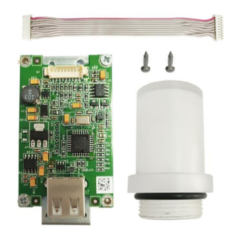
KIT CONTENT
INTERFACE INSTALLATION
Install the RS232 / RS485 / USB Device Interface on the underside of the indicator as
shown.
For TD52P:
1. Separate the terminal from the base by loosening load cell cable male connector.
Remove the interface option cover.
Load cell cable male connector
Interface option cover

EN-2
2. Break off the rib of the interface option cover as shown.
3. Connect the cable to the main board connector as shown. Place the ferrite in the
groove of the rear housing.
4. Install the RS232/RS485/USB Device board. Secure it with the 2 screws.
Connect the cable to the accessory board 12 pin connector.
Rib
Ferrite
Main board
connector 2
Cable
12 Pin Connector
Screw

EN-3
5. Set the function switch to according to the desired function.
Connect the corresponding RS232, RS485 or USB device cable to the applicable
connector.
Refer to Table 1 in the Setup section for the function switch settings.
Refer to Table 2 in the Setup section for RS232RS485 connection for external
serial devices.
6. Fix the output cable with the nylon cable tie.
7. Put the interface option cover back on the terminal.
Function switch
USB Device Socket
RS232/RS485 Connector
Nylon cable tie
Output cable

EN-4
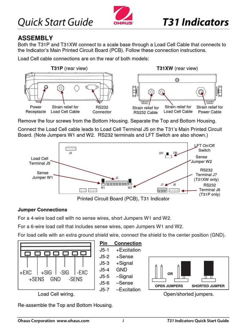
For TD52XW:
1. Separate the terminal from the base by loosening load cell cable female
connector. Remove the interface option cover.
2. Take the rear housing down from the front housing as shown.
screws
Load cell cable male
connector
M25 hole plug

EN-5
3. Connect the cable to the main board connector. Place the ferrite in the slot of the
internal cover as shown.
4. Install the RS232 / RS 485 / USB device board. Secure it with 2 screws
(Note: boss post is 5 and 7). Connect the cable to RS232 / 485 / USB device
board 12 pin connectors.
Cable
Ferrite
Main board connector 2
Boss Post 5, 7

EN-6
5. Pass the RS232 / RS485 / USB device output cable through the cap nut; then
spread the rubber seal and place it over the cable. Now pass the cable through
the body of the cable gland.
12Pin Connector
Function switch
RS232/RS485
connector
screw
RS232 / RS485
Output
M25 Cable Gland
Cap nut
USB Device
Output Cable
M25 Cable Gland
Cap nut

EN-7
6. Toggle the Function switch according to different function. Put the corresponding
RS232 cable, RS485 cable or USB Device cable through the M25 hole. Connect
it to the applicable connectors.
7. Put the rear housing back on the front housing. Re-install the 6 screws.
8. Fasten the M25 gland to the rear housing.
RS232 cable / RS485 cable
USB Device cable
Current loop cable
M25 gland

EN-8
9. Push the rubber seal into the M25 cable gland.
10. Fasten the cap nut of the M25 gland.
For TD52XW with reversed rear cover:
1. Separate the terminal from the base by loosening load cell cable female
connector. Remove the interface option cover.
Rubber seal
Cap nut of M25 gland
Screw
M25 hole plug
Load cell cable male connector

EN-9
2. Take the rear housing down from the front housing as shown.
3. Connect the wire harness 2 to the main board connector 2.
Cable
Main board connector 2

EN-10
4. Install the RS232 / RS485 / USB Device board. Secure it with 2 screws. (Note:
the boss post is 6, 8). Connect the cable to the relay board 12 pin connector.
(Note: the ferrite needs to be positioned nearby the 12 pin connector).
5. Pass the RS232 / RS485 / USB device output cable through the cap nut; then
spread the rubber seal and place it over the cable. Now pass the cable through
the body of the cable gland.
Boss post 6,8
RS232 / RS485
Output
M25 Cable Gland
Cap nut
Screw
12 Pin connector
Ferrite

EN-11
6. Toggle the Function switch according to different function. Put the corresponding
RS232 cable, RS485 cable or USB Device cable through the M25 hole. Connect
it to the 7 Pin connectors.
7. Put the rear housing back on the front housing. Re-install the 6 screws.
USB Device
Output Cable
M25 Cable Gland
Cap nut
Function switch
RS232 cable / 485 cable
Function switch
USB Device cable

EN-12
8. Fasten the M25 gland to the rear housing.
9. Push the rubber seal into the M25 cable gland.
10. Fasten the cap nut of the M25 cable gland.
M25 gland
Rubber Seal
Cap nut of M25 gland

EN-13
SETUP
A two-position switch block is located on the main PCB. These switches function as shown
below.
Table 1
Switch
SW-1
SW-2
Function
Position
0
0
RS232
0
1
RS485
1
0
USB Device
1
1
RS485 Active Terminator
Note: Only one function mode can be available at a given time.
RS232/RS485/USB Device Function
A) The OHAUS Interface is preset to communicate using the following settings: 9600
baud, 8 bits, no parity, no handshake. Determine the RS232/RS485/USB Device
parameters required for the printer or computer that is to be connected. See the
computer or printer documentation if assistance is required. If the parameters do not
match, it will be necessary to change either the indicator's settings, or the computer /
printer settings.
B) Upon installation of the interface, the indicator will recognize the RS232/RS485/USB
Device Interface and add relevant items to the menu. Configure the indicator to the
Switch
USB
Device
COM 1

EN-14
desired RS232/485/USB Device and printing parameters; refer to the indicator's User
Manual for assistance in using the menus.
RS485
RS232
USB Device
Connection
The COM1 port provides an RS-232/RS-485 Device connection for external serial devices.
Table 2 indicates which indicator carries which signal on the COM1 port. Make the
connections as necessary.
COM1
Table 2
Indicator
Signal
232TxD
Transmit RS-232
232RxD
Receive RS-232
232GND
GND
485A
Data +
485B
Data -
485GND
GND

EN-15
2ND RS232 CONFIGURATION
Communication
Options(bold is default)
RS232/
2nd RS232
Configuration
Baud Rate
300, 600, 1200, 2400, 4800, 9600, 19200,
38400, 57600
Parity
7 Even, 7 Odd, 7 None, 8 None
Stop Bit
1 bit, 2 bit
Handshake
None, Xon/Xoff, Hardware
Alt Print CMD
'a' ~ 'z', 'A' ~ 'Z', P
Alt Tare CMD
'a' ~ 'z', 'A' ~ 'Z', T
Alt Zero CMD
'a' ~ 'z', 'A' ~ 'Z', Z
Reset
No/Yes
Print Setup
Assignment
Demand
Stable Only
Off, On(LFT Force On)
Auto On Stable
Mode
Load, Load and Zero
Auto On Accept
Interval
Time
1~50000
MT-Continuous
OH-Continuous
SICS
Reference Balance
Select
Template
Simple, Custom 1, Custom 2, Custom 3,
Custom 4, Custom 5
Edit Template
Field 1~ field 100
Edit String
String 1~ String 10
Reset
No / Yes
Note: Please refer to Indicator Instruction Manual for commands and printouts.
RS485 CONFIGURATION
The address of RS485 can be set from 1 to 99. If Off is selected, there is no address
definition for RS485.
Note: RS485 has the same configuration and print setup as RS232.

EN-16
Modbus
The D5000 indicator supports Modbus RTU, and the address map table is as follow:
Address
bit
description
R/W
40001
32bits displayed weight R
40002
40003
32bits
tare weight
R
40004
40005
bit0~bit8
reserved
R
bit09
net mode
bit10
center of zero
bit11
stable
bit12
Err8.1
bit13
Err8.2
bit14
Err8.3
bit15
Err8.4
40006
32bits scale capacity R
40007
40008
bit0~bit12
reserved
W
bit13
Zero
bit14
Tare
bit15
Clear Zero
AUTO-PRINT OPERATION
Once Auto-Print is activated in the menu, the indicator will send data as required. To
temporarily stop Auto-Printing, press the PRINT key. If there is data in the print buffer the
printer will finish printing this data. A second press will resume Auto-Printing.

EN-17
COMPLIANCE
Mark
Standard
This product complies with the applicable harmonized standards of EU
Directives 2011/65/EU (RoHS), 2014/30/EU (EMC). The EU Declaration of
Conformity is available online at www.OHAUS.com/ce.
FCC Note
This equipment has been tested and found to comply with the limits for a Class A digital
device, pursuant to Part 15 of the FCC Rules. These limits are designed to provide
reasonable protection against harmful interference when the equipment is operated in a
commercial environment. This equipment generates, uses, and can radiate radio frequency
energy and, if not installed and used in accordance with the instruction manual, may cause
harmful interference to radio communications. Operation of this equipment in a residential
area is likely to cause harmful interference in which case the user will be required to correct
the interference at his own expense.
Industry Canada Note
This Class A digital apparatus complies with Canadian ICES-003.
Disposal
In conformance with the European Directive 2012/19/EU on Waste Electrical
and Electronic Equipment (WEEE) this device may not be disposed of in
domestic waste. This also applies to countries outside the EU, per their
spec
ific requirements.
Please dispose of this product in accordance with local regulations at the
collecting point specified for electrical and electronic equipment. If you have
any questions, please contact the responsible authority or the distributor
from wh
ich you purchased this device.
Should this device be passed on to other parties (for private or professional
use), the content of this regulation must also be related.
For disposal instructions in Europe, refer to www.
OHAUS.com/weee.
Thank you for your contribution to environmental protection.

Table of contents
Languages:
Other OHAUS Measuring Instrument manuals

OHAUS
OHAUS TD52 User manual

OHAUS
OHAUS TD52 User manual

OHAUS
OHAUS MB90 User manual

OHAUS
OHAUS MB25 User manual

OHAUS
OHAUS MB95 User manual

OHAUS
OHAUS ST20D User manual

OHAUS
OHAUS STARTER 5000 User manual

OHAUS
OHAUS STARTER 2100 User manual

OHAUS
OHAUS MB90 User manual

OHAUS
OHAUS Defender i-DT61PW User manual

OHAUS
OHAUS Defender 2000 Series User manual

OHAUS
OHAUS T51XW User manual

OHAUS
OHAUS TD52 User manual

OHAUS
OHAUS Ranger 3000 Series User manual
OHAUS
OHAUS a-AB23EC User manual

OHAUS
OHAUS STARTER 3100C User manual

OHAUS
OHAUS MB120 User manual

OHAUS
OHAUS ST Series User manual

OHAUS
OHAUS STARTER 3100C User manual

OHAUS
OHAUS MC2000 User manual