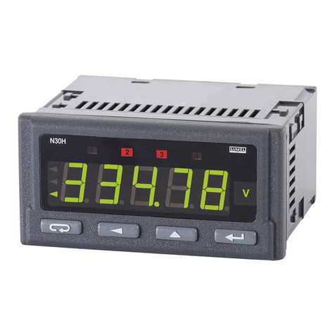
Lumel N20PLUS User manual

1
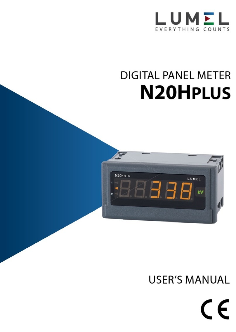
DIGITAL PANEL METER
N20PLUS
USER’S MANUAL

2

3
Contents
1. APPLICATION AND METER DESIGN ........................................ 5
2. METER SET................................................................................. 6
3. BASIC REQUIREMENTS, OPERATIONAL SAFETY................. 6
4. INSTALLATION ........................................................................... 8
5. SERVICE.................................................................................... 10
6. MODBUS REGISTER MAP....................................................... 18
7. ERROR CODES ........................................................................ 22
8. TECHNICAL DATA .................................................................... 23
9. EXECUTION CODES ................................................................ 26

4

5
1. APPLICATION AND METER DESIGN
The N20PLUS meter is a digital programmable panel instrument
destined for measurements of d.c. voltages or d.c. currents: unipolar or
bipolar, temperature through thermocouples (J, K) and Pt100 resistance
thermometers.
The N20PLUS meter has a built-in RS-485 interface and the MODBUS
RTU protocol provided on it, by means of which it is possible to congure
the meter or read measured values from it. The free eCon software
(available at www.lumel.com.pl) is destined for the conguration of the
N20PLUS meter. The meter should be connected to a PC computer via
the RS485 to USB converter, e.g. PD10.
Following parameters can be reprogrammed:
– display colour, individually in three intervals,
– thresholds of displayed overows
– display precision of the result (decimal point),
– highlight of the unit,
– automatic or manual compensation: temperature of ends in
measurements with thermocouples, or wire resistance in Pt100
measurements,
– averaging time of the measurement,
– recalculation of indications (individual characteristic),
– working modes for two outputs of OC type, to choose from 6 work modes;
– RS-485 transmission parameters;
– MODBUS bus settings.
The meter is equipped with two OC type outputs. The output
switching on is signaled by the highlight of the triangular alarm index
situated at the left display side, for the suitable alarm digit. The highlight
colour is always different from the colour of the displayed (measured)
value.
The meter has a galvanic separation between the supply, measuring
inputs and RS485 interface.

6
2. METER SET
The set is composed of:
- N20PLUS meter ........................................ 1 pc
- user’s manual............................................ 1 pc
- clamps to x in the panel......................... 4 pcs
3. BASIC REQUIREMENTS
AND OPERATIONAL SAFETY
Symbols located in this service manual mean:
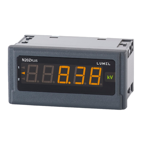
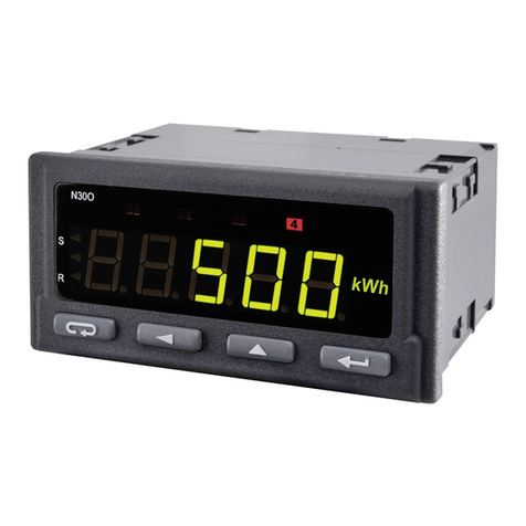
Fig. 1. view of the N20PLUS meter
The protection grade of the meter from the front side is IP65. Dimensions
96 x 48 x 64 mm (including terminals). The meter housing is made of
self-extinguishing plastic.
WARNING!
Warning of potential, hazardous situations. Especially
important, one must acquaint with this before connecting
the meter. The non-observance of notices marked by these
symbols can occasion severe injuries of the personnel and
the damage of the meter.
CAUTION!
Designates a general useful note. If you observe it, handling
of the meter is made easier. One must take note of this,
when the meter is working inconsistently to the expectations.
Possible consequences if disregarded!

7
In the safety service scope, the N20PLUS meter meets the
requirements of the EN 61010-1 standard.
Observations concerning the operational safety:
▪ All operations concerning transport, installation, and commissioning
as well as maintenance, must be carried out by qualied, skilled
personnel, and national regulations for the prevention of accidents
must be observed.
▪ Before switching the meter on, one must check the correctness of
connection to the network.
▪ The removal of the meter housing during the guarantee contract
period may cause its cancellation.
▪ The meter is destined to be installed and used in industrial
electromagnetic environment conditions.
▪ One must remember that in the building installation, a switch or a
circuit-breaker should be installed. This switch should be located
near the device, easy accessible by the operator, and suitably
marked.

8
4. INSTALLATION
The meter has separable strips with screw terminals which enable the con-
nection of external wires of 2.5 mm2. In the version for current measure-
ment, the plug enables permanent xing to the socket by means of screws.
One must prepare a hole of 92+0.6 45+0.6 mm in the panel which the
thickness should not exceed 6 mm. The meter must be introduced from
the panel front with disconnected supply voltage. Before the insertion into
the panel, one must check the correct placement of the seal. After the
meter insertion into the hole, x the meter by means of the clamps ( g. 2.).
Fig. 2. Meter xing.
Fig. 3. Meter overall dimensions

9
4.1. Connection Diagrams
Resistance thermometer RTD
in a two-wire system with manual
compensation
Resistance thermometer RTD
in a three-wire system with automatic
compensation
Thermocouple J, K
Current input
Voltage input
The supply must be connected by a two-wire cable, of a suitable wire
diameter, ensuring its protection by means of an installation cut-out.
Fig. 4. Electrical connections of the N20PLUS meter
Fig. 5. Connections of measurement inputs
N20PLUS Instrukcja obsługi 5
Rys. 3. Gabaryty miernika
4.1. Schematy podłączeń
Rys. 4. Połączenia elektryczne miernika N20PLUS
Rys. 5. Połączenia wejść pomiarowych
Zasilanie należy podłączyć przewodem dwużyłowym, o odpowiedniej średnicy przewodów
zapewniającej jego zabezpieczenie za pomocą bezpiecznika instalacyjnego.
1 2 3
Rezystor termometryczny w
układzie dwuprzewodowym z
kompensacją ręczną
1 2 3
Rezystor termometryczny w
układzie trójprzewodowym z
kompensacją automatyczną
1 2 3 1 2 3
Termoelement J, K
Wejście prądowe,
wejście napięciowe
+ - + -
1 2 3 4 5 6 7 8 9 10 11 12 13 14 15 16
24V GND24V GNDAAL2 AL1 GNDRS485 B A zasilanie
Sygnały pomiarowe
~
supply
measuring signals
N20PLUS Instrukcja obsługi 5
Rys. 3. Gabaryty miernika
4.1. Schematy podłączeń
Rys. 4. Połączenia elektryczne miernika N20PLUS
Rys. 5. Połączenia wejść pomiarowych
Zasilanie należy podłączyć przewodem dwużyłowym, o odpowiedniej średnicy przewodów
zapewniającej jego zabezpieczenie za pomocą bezpiecznika instalacyjnego.
1 2 3
Rezystor termometryczny w
układzie dwuprzewodowym z
kompensacją ręczną
1 2 3
Rezystor termometryczny w
układzie trójprzewodowym z
kompensacją automatyczną
1 2 3 1 2 3
Termoelement J, K
Wejście prądowe,
wejście napięciowe
+ - + -
1 2 3 4 5 6 7 8 9 10 11 12 13 14 15 16
24V GND24V GNDAAL2 AL1 GNDRS485 B A zasilanie
Sygnały pomiarowe
~
N20PLUS Instrukcja obsługi 5
Rys. 3. Gabaryty miernika
4.1. Schematy podłączeń
Rys. 4. Połączenia elektryczne miernika N20PLUS
Rys. 5. Połączenia wejść pomiarowych
Zasilanie należy podłączyć przewodem dwużyłowym, o odpowiedniej średnicy przewodów
zapewniającej jego zabezpieczenie za pomocą bezpiecznika instalacyjnego.
1 2 3
Rezystor termometryczny w
układzie dwuprzewodowym z
kompensacją ręczną
1 2 3
Rezystor termometryczny w
układzie trójprzewodowym z
kompensacją automatyczną
1 2 3
1 2 3
Termoelement J, K
Wejście prądowe,
wejście napięciowe
+ -
+ -
1 2 3 4 5 6 7 8 9 10 11 12 13 14 15 16
24V GND24V GNDAAL2 AL1 GNDRS485 B A zasilanie
Sygnały pomiarowe
~
N20PLUS Instrukcja obsługi 5
Rys. 3. Gabaryty miernika
4.1. Schematy podłączeń
Rys. 4. Połączenia elektryczne miernika N20PLUS
Rys. 5. Połączenia wejść pomiarowych
Zasilanie należy podłączyć przewodem dwużyłowym, o odpowiedniej średnicy przewodów
zapewniającej jego zabezpieczenie za pomocą bezpiecznika instalacyjnego.
1 2 3
Rezystor termometryczny w
układzie dwuprzewodowym z
kompensacją ręczną
1 2 3
Rezystor termometryczny w
układzie trójprzewodowym z
kompensacją automatyczną
1 2 3
1 2 3
Termoelement J, K
Wejście prądowe,
wejście napięciowe
+ - + -
1 2 3 4 5 6 7 8 9 10 11 12 13 14 15 16
24V GND24V GNDAAL2 AL1 GNDRS485 B A zasilanie
Sygnały pomiarowe
~

10
5. SERVICE
5.1. Display Description
5.2. Messages after the Supply Connection
After connecting the supply, the meter displays the X, where
Xthe letter marking the execution of the meter: U– voltage measure-
ment, I– current measurement, r– measurement of Pt100 temperature,
t– measurement of the temperature by thermocouples, s– custom-made
execution. Next, the program version is displayed in the shape r x.xx –
where x.xx is the number of the actual program version or the number of
the custom-made execution.
Till the time to obtain the required number of correct measurements (acc.
to the table 1), the actual value from the measurement 1 is displayed,
signaled by the highlighted index of the actual value.
In case of an error occurrence or an over ow of the range value, a mes-
sage described in the section 7 will be displayed on the display.
Over ows of the measuring range are additionally signaled by the actual
value signal index.
Alarm
indexes
Highlighted
unit
Measured
value
Indexes of actual value
displaying
Fig. 6. Frontal panel

11
5.3. Meter Configuration
The free eCon software (available at www.lumel.com.pl) is destined for
the N20PLUS meter conguration. The meter should be connected to a
PC computer via the RS485 to USB converter, e.g. PD10, and then in the
E-Con program, select the transmission parameters according to those
set in the meter.
CAUTION! One must carry out the programming of meter parameters
when measuring circuits are switched off!
5.4. Parameters description
5.4.1. Display settings
After choosing the group: - Display settings, following elements are
possible to be congured:
a) display colours of the measured value. The displayed range is divided
into three zones separated by KpL and KpH values (suitably the lower
threshold KpL and the upper threshold KpH of display colour change
– g.9). The colour of displayed numbers for each zone is selected
from three accessible colours: green, orange and red. KpL and KpH
values are set by the user and concern the displayed value (i.e. taking
also into consideration the individual characteristic). The manufacturer
value KpL is equal 100% of the rated value, however KpH is equal
105% of the rated value, e.g. for a 10 V meter execution they are
respectively: for KpL – 10 V and for KpH – 10.5 V.
Caution! After setting the individual characteristic, KpL and KpH
values are not automatically updated.
N20PLUS Instrukcja obsługi 7
Rys. 7. konfiguracja kolorów wyświetlania
b) punkt dziesiętny - precyzja pomiaru. Do wyboru jest 5 możliwych konfiguracji wyświetlania,
przy czym przy wyborze należy się kierować dokładnością pomiaru, np: dla zakresu 10 V –
błąd pomiaru wynosi 0,02 V, więc wybór precyzji z trzema miejscami po przecinku nie daje
dokładniejszych pomiarów. Fabrycznie dla wykonania z pomiarem napięcia i prądu ustawiona
jest precyzja 000,00; dla wykonania z pomiarem temperatury przez Pt100 – 0000,0; dla
wykonania z pomiarem temperatury przez termopary – 00000.
c) podświetlenie jednostki. Podświetlenie jednostki może być włączone lub wyłączone.
Fabrycznie jest włączone.
5.4.2. Parametry pomiaru
Pomiar możemy skonfigurować poprzez zmianę następujących elementów:
a) automatyczna kompensacja (temperatury zacisków w wykonaniu z pomiarem
termoelementem lub rezystancji przewodów dla wykonania z pomiarem Pt100). Wyłączenie
umożliwia podanie wartości temperatury zacisków lub rezystancji przewodów wykorzystywanej
w obliczeniach. Jako rezystancję podaje się sumę obu przewodów. Fabrycznie jest włączona.
b) czas uśredniania: do czasu uzyskania wymaganej liczby poprawnych pomiarów (zgodnie z
tablicą 1) wyświetlana jest wartość chwilowa z 1 pomiaru. Po zmierzeniu określonej liczby
pomiarów, wyświetlana jest średnia arytmetyczna ze zmierzonych pomiarów. Kolejne pomiary
dodawane są na zasadzie „okna kroczącego” tzn. najwcześniejszy pomiar jest odrzucany a na
jego miejsce wstawiany jest ostatnio zmierzony. Zmierzenie wartości spoza zakresu
pomiarowego powoduje wyświetlenie przekroczenia i rozpoczęcie liczenia pomiarów
poprawnych od nowa. Fabrycznie czas ustawiony jest na 1s
Tablica 1
Czas
uśredniania
Ilość pomiarów
uśrednianych
Uaktualnianie wartości wyświetlanej
(czas trwania 1 pomiaru)
0,5 s 2 co 0,5 s
1 s 7 co 0,5 s
3 s 20 co 0,5 s
5 s 33 co 0,5 s
10 s 67 co 0,5 s
15 s 100 co 0,5 s
20 s 133 co 0,5 s
c) progi wyświetlanych przekroczeń: można zawężać granice poza którymi wyświetlane będą
przekroczenia z uwzględnieniem charakterystyki indywidualnej. Gdy wartość mierzona jest
poza zakresem pomiarowym 0...110% wartości znamionowej (np. dla wykonania 10 V jest to
zakres -1...11 V) wyświetlane jest przekroczenie, fabrycznie ustawiony jest zakres
-19999...99999.
d) włączenie charakterystyki indywidualnej. Fabrycznie charakterystyka jest wyłączona.
Konfiguracja charakterystyki indywidualnej polega na zdefiniowaniu punktów charakterystyki
liniowej, służącej do przeliczenia wartości mierzonej na wartość wyświetlaną (Rys. 8).
KpL
KpH
wartość wyświetlana
displayed value
Fig. 7. Display color conguration

12
5.4.1. Measurement settings
We can congure the measurement by changing the following elements:
a) Compensation (of terminal temperatures in the version with thermo-
couple measurement or resistance of wires for the version with Pt100
measurements). The switching of the automatic compensation off,
enables to give terminal temperature values or the wire resistance
used in calculations. As the resistance, one must give the sum of
both wires. At the beginning, the compensation is switched by the
manufacturer on.
b) Averaging time: till the time to obtain the required number of correct
measurements (according to the table 1), the actual value from 1 mea-
surement is displayed. After measuring a denite number of measure-
ments, the arithmetic mean of measured measurements is displayed.
Subsequent measurements are added on the principle of “rolling win-
dow”, i.e. the earliest measurement is discarded and the most recently
measured one is put in its place. The measurement of a value beyond
the measuring range causes the display of overow and the start to
count correct measurements from the beginning. The time is set on 1
s by the manufacturer.
b) decimal point – measurement precision. We have 5 possible display
congurations at choice.
When choosing, one must follow the measurement precision, e.g.:
for the 10 V range – the measurement error is 0.02 V, so the choice
of precision with three places after the decimal point does not give
more precise measurements. When manufacturing, for executions
with voltage and current measurements, the precision 000.00 is set;
for executions with Pt100 temperature measurement – 0000.0; for
execution with the temperature measurement through thermocouples
– 00000.
c) unit highlight. The unit highlight can be enabled or disabled. When
manufacturing it is enabled.

13
Table 1
0.5 s 2 every 0.5 s
1 s 7 every 0.5 s
3 s 20 every 0.5 s
5 s 33 every 0.5 s
10 s 67 every 0.5 s
15 s 100 every 0.5 s
20 s 133 every 0.5 s
Averaging
time
Number of
averaging time Updating of displayed values
c) thresholds of displayed overows: one can narrow limits beyond which
overows will be displayed, taking into consideration the individual
characteristic.When the measured value is beyond 0…110% of the
rated value (e.g. for the 10 V execution, it is the range -1…11 V),
the overow is displayed. In manufacturing conditions, the range
–19999…99999 is set.
d) switching the individual characteristic on. In manufacturing conditions
the characteristic is switched off.
The conguration of the individual characteristic consists in dening
the points of the linear characteristic used to convert the measured
value into the displayed value (Figure 8).
N20PLUS Instrukcja obsługi 8
Rys. 8. Charakterystyka indywidualna
Przykładowo, aby uzyskać wyświetlanie wartości w kV, należy ustawić punkty X1, X2, Y1, Y2
następująco:
X1 = 0, Y1 = 0, X2 = 10, Y2 = 1
Zapis ten oznacza, że dla każdej wartości mierzonej z zakresu 0...10, będzie wyliczona
wartość wyświetlona z zakresu 0...1.
Mając punkty X1, Y1, X2, Y2, należy wyznaczyć współczynniki A i B prostej o równaniu
y
=
A
⋅
x
+
B
zgodnie z zasadą:
A
=
Y
1
−
Y
2
X
1
−
X
2
B
=
Y
1
−
Y
1
−
Y
2
X
1
−
X
2
⋅
X
1
Współczynniki A i B są parametrami charakterystyki indywidualnej.
5.4.3. Parametry alarmów
W mierniku N20PLUS dostępne są dwa alarmy. Oba pracują niezależnie i każdy z nich ma 6
trybów pracy: n-on, n-off, on, off, hon i hoff, które zostały przedstawione na rys. 9. Progi alarmowe
Aoff i Aon ustawiane są w wartościach wielkości mierzonej z uwzględnieniem charakterystyki
indywidualnej. Fabrycznie oba alarmy są ustawione w trybie n-on.
Dodatkowo, dla każdego alarmu można ustawić parametr opóźnienia przełączenia stanu.
1
0
wyjście
włączone
wyjście
wyłączone
AonAoff wielkość mierzona
Wyjście
alarmu
1
0
wyjście
włączone
wyjście
wyłączone
AonAoff wielkość mierzona
Wyjście
alarmu
a) n-on b) n-off
1
0
wyjście
włączone
wyjście
wyłączone
AonAoff wielkość mierzona
Wyjście
alarmu
wyjście
wyłączone
1
0
wyjście
włączone
wyjście
wyłączone
AonAoff wielkość mierzona
Wyjście
alarmu
wyjście
włączone
c) on d) off
Rys 9. Typy alarmów: a) n-on, b) n-off c) on d) off.
Pozostałe typy alarmu: hon – zawsze załączony; hoff – zawsze wyłączony.
X1 X2 wartość mierzona
Y2
Y1
wartość
wyświetlana
measured value
displayed
value
Fig. 8. Individual characteristic

14
5.4.3. Setting of Alarm Parameters
Two alarms are available in the N20PLUS meter. Both alarms
are working independently and each of them has 6 working modes:
n-on, n-off, on, off, hon and hoff, which are presented on the g. 9. Alarm
thresholds Aoff and Aon are set in values of the measured quantity taking
into consideration the individual characteristic. In manufacturing conditions
both alarms are set on the n-on mode.
Additionally, for each alarm, you can set the parameter for the
delay of switching the state.
a) n-on
b) n-off
For example, to get values in kV, set points X1, X2, Y1, Y2 as follows:
X1 = 0, Y1 = 0, X2 = 10, Y2 = 1
This record means that for each measured value in the range
0 ... 10, the displayed value in the range 0 ... 1 will be calculated.
Having the points X1, Y1, X2, Y2, the coefcients A and B of the straight
line with the equation should be determined
N20PLUS Instrukcja obsługi 8
Rys. 8. Charakterystyka indywidualna
Przykładowo, aby uzyskać wyświetlanie wartości w kV, należy ustawić punkty X1, X2, Y1, Y2
następująco:
X1 = 0, Y1 = 0, X2 = 10, Y2 = 1
Zapis ten oznacza, że dla każdej wartości mierzonej z zakresu 0...10, będzie wyliczona
wartość wyświetlona z zakresu 0...1.
Mając punkty X1, Y1, X2, Y2, należy wyznaczyć współczynniki A i B prostej o równaniu
y
=
A
⋅
x
+
B
zgodnie z zasadą:
A
=
Y
1
−
Y
2
X
1
−
X
2
B
=
Y
1
−
Y
1
−
Y
2
X
1
−
X
2
⋅
X
1
Współczynniki A i B są parametrami charakterystyki indywidualnej.
5.4.3. Parametry alarmów
W mierniku N20PLUS dostępne są dwa alarmy. Oba pracują niezależnie i każdy z nich ma 6
trybów pracy: n-on, n-off, on, off, hon i hoff, które zostały przedstawione na rys. 9. Progi alarmowe
Aoff i Aon ustawiane są w wartościach wielkości mierzonej z uwzględnieniem charakterystyki
indywidualnej. Fabrycznie oba alarmy są ustawione w trybie n-on.
Dodatkowo, dla każdego alarmu można ustawić parametr opóźnienia przełączenia stanu.
1
0
wyjście
włączone
wyjście
wyłączone
AonAoff wielkość mierzona
Wyjście
alarmu
1
0
wyjście
włączone
wyjście
wyłączone
AonAoff wielkość mierzona
Wyjście
alarmu
a) n-on b) n-off
1
0
wyjście
włączone
wyjście
wyłączone
AonAoff wielkość mierzona
Wyjście
alarmu
wyjście
wyłączone
1
0
wyjście
włączone
wyjście
wyłączone
AonAoff wielkość mierzona
Wyjście
alarmu
wyjście
włączone
c) on d) off
Rys 9. Typy alarmów: a) n-on, b) n-off c) on d) off.
Pozostałe typy alarmu: hon – zawsze załączony; hoff – zawsze wyłączony.
X1 X2 wartość mierzona
Y2
Y1
wartość
wyświetlana
according to the rule:
Coefcients A and B are individual characteristic parameters.

15
c) on
d) off
Remaining types of the alarm: h-on – always switched on;
h-off – always switched off.
Fig. 9. Alarm types: a) n-on, b) n-off, c) on, d) off
5.4.4. Communication Parameters
The N20PLUS meter is equipped with an isolated
RS-485 interface and communication takes place via the Modbus RTU
protocol. The following parameters are available to congure the correct
communication:
- address on the Modbus, can take values from the range 1 ... 247
- baud rate, are available: 4800, 9600, 19200, 38400, 57600,
115200 bps
- transmission mode, available for selection: 8N2, 8E1, 8O1, 8N1

16
5.4. Manufacturer Parameters
Table 2
Parameter description Range/value Manufacturer value
Display colour of the measured
upper value red, green, orange red
Display colour of the measured
middle value red, green, orange orange
Display colour of the measured
lower value red, green, orange green
Upper threshold - KpH -19999…99999 105% of rated value Un,
In or 200°C
Lower threshold - KpL -19999…99999 100% of rated value Un,
In, or 100°C
Decimal point 00000, 0000.0, 000.00,
00.000, 0.0000,
000.00 for U,I, 00000 for
thermocouples J and K
0000.0 for Pt100
Highlight of the measured unit switched off, switched on switched on
Automatic compensation of
the terminal temperature/wire
resistance
switched off, switched on
switched on (for Pt100,
thermocouples J and K),
switched off for other
executions
Manual compensation value:
terminal temperature
wire resistance
in other cases
-20…60°C
0…20 Ω
0
40°C
0 Ω
0
Averaging time 0.5 s, 1 s, 3 s; 5 s, 10 s,
15 s, 20 s, 1 s
Upper overow of the
measurement -19999…99999 99999
Lower overow of the
measurement -19999…99999 -19999
Individual characteristic switched off, switched on switched off
Parameter aof the individual
characteristic -19999…99999 1
Parameter bof the individual
characteristic -19999…99999 0

17
Action mode of the alarm output 1 n-on, n-off, on, off, h-on,
h-off n-on
Upper value of the alarm 1
switching - Aon -19999…99999 105% of rated value Un,
In, or 200°C
Lower value of the alarm 1
switching - Aoff -19999…99999 100% of rated value Un,
In, or 100°C
Delay of the alarm 1 switching
time 0…120 0 second
Action mode of the alarm output 2 n-on, n-off, on, off, h-on,
h-off n-on
Upper value of the alarm 2
switching - Aon -19999…99999 105% of rated value Un,
In, or 200°C
Lower value of the alarm 2
switching - Aoff -19999…99999 100% of rated value Un,
In, or 100°C
Delay of the alarm 2 switching
time 0…120 0 second
Modbus device address 1...247 1
Baud rate 4800, 9600, 19200,
38400, 57600, 115200 9600
Transmission mode 8N2, 8E1, 8O1, 8N1 8N2

18
6. MAP OF MODBUS REGISTERS
In the N20PLUS meter, the data is placed in 16 and 32 bit registers.
Parameters and measured values of the meter are placed in the address
space in a way depending on the variable value type. In 16-bit registers,
bits are numbered from the youngest to the oldest (b0-b15). 32-bit regis-
ters contain oat numbers. The list of available registers is presented in
Table 3. The ranges of changes in the value of registers are presented
in tables 4 and 5.
Table 3
Address range Value type Description
4000 - 4023 Integer (16 bits) Configuration of meter operation
parameters (fixed-point parameters).
Value placed in one 16-bit register.
7600 - 7609 Float (32 bits) Configuration of meter operation
parameters (oating point parameters).
Value placed in one 32-bit register.
7610 - 7611 Float (32 bits) Measured values (oating point). Value
placed in one 32-bit register.
Table 4
Address Register
type Description Changes range
4000 RW Decimal point of the display
(display precision)
0 - 00000
1 - 0000.0
2 - 000.00
3 - 00.000
4 - 0.0000
4001 RW Unit backlight 0 – off
1 – on
4002 RW Display color for values below
the KpL threshold (Fig. 7) set
in register 7603
0 - orange
1 - red
2 - green

19
4003 RW Display color for values
between KpL and KpH
thresholds (Fig. 7) set in
registers 7602 and 7603
0 - orange
1 - red
2 - green
4004 RW Display color for values above
the KpH threshold (Fig. 7) set
in register 7602
0 - orange
1 - red
2 - green
4005 RW Alarm type 1 (section 5.4.3) 0 – n-on
1 – n-off
2 – on
3 – off
4 – hon
5 – hoff
4006 RW Alarm 1 delay time 0...120
4007 RW Alarm type 2 (section 5.4.3) 0 – n-on
1 – n-off
2 – on
3 – off
4 – hon
5 – hoff
4008 RW Alarm 2 delay time 0...120
4009 RW Switching on of individual
characteristics.Characteristics
parameters placed in registers
7600 and 7601
0 – individual char. off
1 – individual char. on
4010 RW Averaging time (section 5.4.2 b) 0 – 0.5 s
1 – 1 s
2 – 3 s
3 – 5 s
4 – 10 s
5 – 15 s
6 – 20 s
4011 RW Temperature compensation
mode of terminal / wire
resistance
0 - manual, value in
reg. 7610
1 - automatic

20
4012 R Restoring factory parameters
of the meter
0 - do not do anything
1 - restore parameters
4013 R The meter status, read only
value, represents the current
operating status.
4014 RW reserved Not applicable
4015 R reserved Not applicable
4016 R reserved Not applicable
4017 R reserved Not applicable
4018 R Meter’s serial number (older
16 bits of 32-bit value)
Not applicable
4019 R Meter’s serial number
(younger 16 bits of 32-bit
value)
Not applicable
4021 RW Baud rate (change requires
acceptance by writing to
registry 4023)
0 – 4800
1 – 9600
2 – 19200
3 – 38400
4 – 57600
5 – 115200
4022 RW Transmission mode (change
requires acceptance by writing
to registry 4023)
0 – 8N2
1 – 8E1
2 – 8O1
3 - 8N1
4023 RW Application of transmission
parameters.
0 - do not do anything
1 - apply changes
Table of contents
Other Lumel Measuring Instrument manuals
Popular Measuring Instrument manuals by other brands

Elma Instruments
Elma Instruments Elma 9200BT manual

Hioki
Hioki CT9691 installation manual

Exotek Instruments
Exotek Instruments MC-60CPA user manual

PCE Americas
PCE Americas PCE-WM 1 manual

Dwyer Instruments
Dwyer Instruments RVM Specifications-installation and operating instructions

ELMETRON
ELMETRON CX-461 user manual

Airmar
Airmar WeatherStation 200WXRS Owner's guide & installation instructions

Qu-Bit Electronix
Qu-Bit Electronix EON manual

Velleman
Velleman DVM8080 user manual

KROHNE
KROHNE OPTIMASS 1000 Series Guidelines for use

Simpson
Simpson S664 Operation manual

Cleveland Controls
Cleveland Controls 6650 instruction manual