V. Warnings - Don'ts
Don’t use tiller with one hand.
Keep
both hands on handles with
fingers and
thumbs encircling the handles, while tines
are moving, and engine is running.
Don’t overreach. Keep a good footing at
all times.
Don’t run with the machine, walk.
Don’t work on excessively steep slopes.
Don’t attempt to clear tines while they
are moving. Never try to remove jammed
material before switching the engine off
and making sure the tines have stopped
completely.
Don’t allow children or incapable
people to operate this tiller.
Don’t operate while under
the influence of alcohol or drugs.
Don’t attempt to repair this tiller. Have
repairs made by a qualified dealer or
repairman. See that only original MANTIS
parts are used.
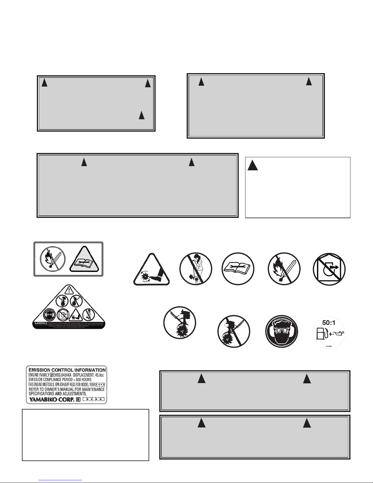
WARNING • DANGER
HANDLE FUEL WITH CARE, IT IS HIGHLY FLAMMABLE. FUELING A H T ENGINE R NEAR AN IGNITI N S URCE CAN
CAUSE A FIRE AND RESULT IN SERI US PERS NAL INJURY AND/ R PR PERTY DAMAGE.
Always use fresh gasoline in the fuel
mixture. Stale gasoline can cause damage.
Always store fuel in containers
specifically designed for this purpose.
Always pull starter cord slowly until
resistance is felt. Then pull cord rapidly to
avoid kickback and prevent arm or hand
injury.
Always operate engine with spark
arrestor installed and operating properly.
The use of spark arrestor mufflers is
required by law in the state of California
(Section 4442 of the California Public
Resources Code), as well as in other states
or municipalities. Federal laws apply on
federal lands.
Stop the engine whenever you leave the
machine.
Allow the engine to cool before storing
in any enclosure.
If the fuel tank needs to be drained, this
should be done outdoors.
Don’t
fuel, refuel or check fuel while
smoking, or near an open flame or other
ignition source. Stop engine and be sure it is
cool before refueling.
Don’t
leave the engine running while the
tiller is unattended. Stop engine before
putting the tiller down or while transporting
from one place to another.
Don’t
refuel, start or run this tiller
indoors or in an improperly ventilated area.
Don’t
run engine when electrical system
causes spark outside the cylinder. During
periodical checks of the spark plug, keep
plug a safe distance from cylinder to avoid
burning of evaporated fuel from cylinder.
Don’t
check for spark with spark plug or
plug wire removed. Use an approved tester.
Don’t
crank engine with spark plug
removed unless spark plug wire is
disconnected. Sparks can ignite fumes.
Don’t
run engine when the odor of gas oline
is present or other explosive conditions exist.
Don’t
operate the unit if gasoline is
spilled. Clean up spill completely before
starting engine.
Don’t
operate your tiller if there is an
accumulation of debris around the muffler,
and cooling fins.
Don’t
touch hot mufflers, cylinders
or cooling fins as contact may cause
serious burns.
Don’t change the engine governor
setting or over speed the engine.
VI. Engin /Fu l Warnings - Do’s
VII. Engin /Fu l Warnings - Don’ts
IV. Warnings - Do’s
R ad and und rstand th own r’s
manual. Pay particular att ntion to all
s ctions r garding saf ty.
1. Always keep a firm grip on both
handles while the tines are moving and/or
the engine is running. BE AWARE!! The
tines may coast after throttle trigger is
released. Make sure tines have come to a
complete stop and engine is off before
letting go of the tiller.
2. Always maintain a firm footing and
good balance. Do not overreach while
operating the tiller. Before you start to use
the tiller check the work area for obstacles
that might cause you to lose your footing,
balance or control of the machine.
3. Thoroughly inspect the area where
equipment is to be used and remove all
objects, which can be thrown by the
machine.
4. Always keep area clear of children,
pets, and bystanders.
5. Always stay alert. Watch what you
are doing and use common sense. Do not
operate unit when fatigued.
6. Always dress properly. Do not wear
loose clothing or jewelry, they might get
caught in moving parts. Use sturdy gloves.
Gloves reduce the transmission of vibration
to your hands. Prolonged exposure to
vibration can cause numbness and other
ailments.
7. Whil working, always wear
substantial footwear and long trousers. Do
not operate the equipment when barefoot
or wearing open sandals.
8. Always wear ear and eye protection.
Eye protection must meet ANSI Z 87.1. To
avoid hearing damage, we recommend
hearing protection be worn whenever using
the equipment.
9. To r duc fir hazard, keep the
engine, and petrol/gas storage area free of
vegetative material and excessive grease.
10. Start the engine carefully, according
to the manufacturer’s instructions and with
feet well away from tool(s).
11. K p all nuts, bolts and screws tight
to be sure the equipment is in safe working
condition.
12. Us xtr m caution when reversing
or pulling the machine towards you.
13. Work only in daylight or good
artificial light.
14. Always be sure of your footing on
slopes.
15. Ex rcis extreme caution when
changing direction on slopes.
16. Always keep a safe distance
between two or more people when
working together.
17. Always inspect your unit before
each use and ensure that all handles,
guards and fasteners are secure, operating,
and in place.
18. Always maintain and examine your
Tiller with care. Follow mainten ance
instructions given in manual.
19. Always store tiller in a sheltered
area (a dry place), not accessible to
children. The tiller as well as fuel should
not be stored in a house.
4
!
!