Mantracourt DCell User manual

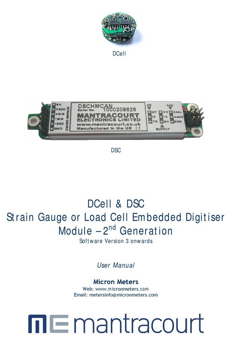
DCell
DSC
DCell & DSC
Strain Gauge or Load Cell Embedded Digitiser
Module MantraCAN – 2
nd
Generation
Software Version 3 onwards
User Manual
MICRON METERS
www.micronmeters.com

Mantracourt Electronics Limited DCell & DSC MantraCAN User Manual
1
Contents
Chapter 1 Introduction ................................................................................................................. 4
Overview 4
Key Features 4
Special Facilities 5
Version 3 Additions and Enhancements 5
The Product Range 6
Which Device To Use 6
Additional DCell & DSC Variants Available 6
Some Application Examples 7
Chapter 2 Getting Started with the Evaluation Kit............................................................................... 8
The Evaluation Kit 8
Contents 8
Checking the Device Type 9
Connecting Up The Evaluation Kit 9
Initial Checks 9
Instrument Explorer 9
What Can Instrument Explorer Do? 9
Installing Instrument Explorer 9
Running the Instrument Explorer Software 10
Instrument Explorer Icon 10
Instrument Settings 11
Viewing Device Data 12
Instrument Explorer Parameter List 12
Connecting a Load Cell 13
DSJ1 Evaluation Board Sensor Connections 14
Performing A System Calibration 15
Chapter 3 Explanation o Category Items .........................................................................................20
Communications 20
ID, NODEIDL, NODEIDH 20
Example 20
CAN Bit Rate, BPS 21
Identifier Size, IDSIZE 21
CAN Bus, CANTXERR, CANRXERR, CANSTATUS 21
CANTXERR 21
CANRXERR 22
CANSTATUS 22
Streaming 22
Configuring Output Message Streams 22
Message Streams 22
Streaming Types, STRMTYPE 22
Starting and stopping Streaming, STRMON, STRMOFF 22
Message Configuration 23
Custom Start / Stop 24
Start Streaming 24
Stop Streaming 25
Data Types 26
Sub Formats 26
Message Output Examples 27
Streaming Start / Stop Examples 27
Information 27
Software Version, VER 27
Serial Number, SERL and SERH 27
Strain Gauge 28
mV/V output, MVV 28
Nominal mV/V level, NMVV 28
mV/V Output In Percentage Terms, ELEC 28

Mantracourt Electronics Limited DCell & DSC MantraCAN User Manual
2
Temperature Value, TEMP 28
Output Rate Control, RATE 28
Dynamic Filtering, FFST and FFLV 28
Cell 30
Temperature Compensation In Brief 30
Cell Scaling, CGAI, COFS 30
Two Point Calibration Calculations and Examples 30
Calibration Methods 31
Cell Limits, CMIN, CMAX 31
Linearisation In Brief 32
System 32
System Scaling, SGAI, SOFS 32
Example of calculations for SGAI and SOFS 32
System Limits, SMIN, SMAX 33
System Zero, SZ 33
System Outputs, SYS, SOUT 33
Reading Snapshot, SNAP, SYSN 33
Control 34
Shunt Calibration Commands, SCON and SCOF 34
Digital Output, OPON and OPOF 34
Flags 34
Diagnostics Flags, FLAG and STAT 34
Latched Warning Flags (FLAG) 34
Meaning and Operation of Flags 35
Dynamic Status Flags (STAT) 36
Meaning and Operation of Flags 36
Output Update Tracking 36
User Storage 36
USR1…USR9 36
Reset 37
The Reset command, RST 37
WARNING: Finite Non-Volatile Memory Life 37
Chapter 4 The Readings Process ....................................................................................................38
Flow diagram 38
Cell & System Scaling 39
Calibration Parameters Summary and Defaults 40
Chapter 5 Temperature Compensation ............................................................................................41
Purpose and Method of Temperature Compensation 41
Temperature Module Connections and Mounting (DTEMP) 41
Control Parameters 42
Internal Calculation 42
The Temperature Measurement 43
How to Set Up a Temperature Compensation 43
Parameter Calculations 44
Chapter 6 Linearity Compensation .................................................................................................45
Purpose and Method of Linearisation 45
Control Parameters 45
Internal Calculation 45
How to Set Up Linearity Compensation 46
Parameter Calculations and Example 46
Chapter 7 Sel -Diagnostics............................................................................................................48
Diagnostics Flags 48
Diagnostics LED 48
Chapter 8 MantraCAN Communication Protocol .................................................................................49
Basic Command Structure 49
Read 49
Example of Read 50
Write 50

Mantracourt Electronics Limited DCell & DSC MantraCAN User Manual
3
Example of Write 51
Execute A Command 51
Example Of Execute A Command 51
Data Type Conversions and Rounding 52
Chapter 9 So tware Command Re erence .........................................................................................53
Commands in Access Order 53
Chapter 10 Installation ................................................................................................................57
Before Installation 57
Physical Mounting 57
Electrical Protection 57
Moisture Protection 57
Soldering Methods 59
Power Supply Requirements 59
Cable Requirements 59
Strain Gauge input (DSC) 59
Power and Communication 59
Temperature Sensor 60
Identifying Strain Gauge Connections 60
DCell Input Connections 60
DSC Input Connections 60
Identifying Bus-End Connections 61
DCell Bus Connections 61
DSC CAN Versions-Bus Connections 61
Strain Gauge Cabling and Grounding Requirements 62
DCell Strain Gauge Wiring 62
DCell Strain Gauge Wiring Arrangement 62
Key Requirements 62
Key Requirements 62
Communications Cabling and Grounding Requirements 63
DCell Power and Communications Wiring 63
DCell Bus-End Arrangement 63
DSC4 Versions- Power and Communications Wiring 63
DSC4 Versions-Bus-End Arrangement 63
Key Requirements 63
Suitable Cable Types 64
DCell/DSC CAN Bus Cable 64
Indication Of Maximum Bus Length 64
CAN Bus Connections for Multiple DCells 65
CAN Bus Connections for Multiple DSC Versions 65
Key Requirements 66
Bus Layout and Termination 66
Loading 66
Strain Gauge Sensitivity Adjustment (DSC ONLY) 66
Identifying the DSC ‘Rg’ Resistor 66
Chapter 11 Troubleshooting .........................................................................................................68
LED Indicator 68
No Communications 68
Bad Readings 68
Unexpected Warning Flags 69
Problems with Bus Baud Rate 69
Recovering a ”lost” DCell/DSC 69
Resetting to default ID 69
First Command 69
Second Command 69
Chapter 12 Speci ications.............................................................................................................70
Technical Specifications DSC/DCELL High Stability 70
Technical Specifications DSC/DCELL Industrial Stability 71
Mechanical Specification for DSC 72

Mantracourt Electronics Limited DCell & DSC MantraCAN User Manual
4
Mechanical Specification for DCell 72
CE Approvals 72
Chapter 1 Introduction
This chapter provides an introduction to DCell/DSC products, describing the product range, main features and
application possibilities
Overview
The DCell and DSC products are miniature, high-precision Strain Gauge Converters; converting a strain gauge sensor
input to a CAN output They allow multiple high precision measurements to be made over a low-cost 2-wire link
Outputs can be accessed directly by PLCs or computers, or connected via various types of network, all without
compromising accuracy
The device is configurable via a proprietary MantraCAN protocol but is able to stream data in a customisable manner
to suit most CAN networks i.e. CANopen® or J1 3 .
This streamed data does not support any interaction, parameter writing or action commands. However all this can be
achieved using the MantraCAN protocol.
Customisable start and stop messages allow the instrument streaming to be controlled via the host CAN network.
Key Features
Ultra-miniature
The DCell ‘puck’ format can be fitted inside most load cell pockets, and similar restricted spaces The DSC cards
are similarly very small, optimised for mounting as a component onto custom PCBs
High-precision Industrial Version.
25ppm basic accuracy (equates to 16 bit resolution)
High-precision High Stability
5ppm basic accuracy (equates to 18 bit resolution) with comparable stability – far exceeds standard instrument
performance
Low-power
Low-voltage DC supply (5 6V min), typically 40mA for RS485 and 52mA for RS232 (including 350R strain gauge)
Adjustable sensitivity
Configured for standard 2 5mV/V full-scale strain gauges as supplied
A single additional resistor configures the input between 0 5 and 100 mV/V full-scale
Temperature sensing and compensation (optional)
An optional temperature sensor module is available and advanced 5-point temperature-compensation of
measurement
Linearity compensation
Advanced 7-point linearity compensation
CAN Output
Lower-cost cabling, improved noise immunity, and longer cable runs with no accuracy penalty
Device addressing allows up to 127 devices on a single bus, drastically reducing cabling cost and complexity
Two-way communications allow in-situ re-calibration, multiple outputs and diagnostics
No separate measuring instruments needed
Digital calibration
Completely drift-free, adjustable in-system and/or in-situ via standard communications link
Two independent calibration stages for load cell-and-system-specific adjustments
Programmable compensation for non-linearity and temperature corrections
Calibration data is also transferable between devices for in-service replacement

Mantracourt Electronics Limited DCell & DSC MantraCAN User Manual
5
Sel -diagnostics
Continuous monitoring for faults such as strain overload, over/under-temperature, broken sensors or unexpected
power failure
All fault warnings are retained on power-fail
Special Facilities
Output Capture Synchronisation
A single command instructs all devices on a bus to sample their inputs simultaneously, for synchronised data
capture
Output Tare Value
An internal control allows removal of an arbitrary output offset, enabling independent readings of net and gross
measurement values
Dynamic Filtering
Gives higher accuracy on stable inputs, without increased settling time
Programmable Output Modes
Output rate control enables speed/accuracy trade-off
ASCII output version provides decimal format control and continuous output mode for ‘dumb terminal’ output
Unique Serial Number
Every unit carries a unique serial-number tag, readable over the communications link
Communications Error Detection
CAN transmit and receive error counts along with CAN bus status can be read from the device
External Temperature Sensing (optional)
An external temperature module for improved accuracy (especially tracking changing temperature conditions)
So tware Reset
A special communications command forces a device reboot, as a failsafe to ensure correct operation
Version 3 dditions and Enhancements
The following are an outline only more detail will be found further on in this manual
DCell
•Easy mounting via a 2mm screw
•Connection via solder holes to either side of PCB
•Lower profile, dual PCB construction
DSC
•Additional I/O
•Easier shielding connection at load cell connector end
DCell & DSC
•Bit rates to 1 Mbps
•Higher sampling rate Sampling to 200Hz can now be achieved Also more sampling rates are available as
follows 1, 2, 5, 10, 20, 50, 60, 100 & 200Hz
•Lower cost With new technology and further use of miniaturisation the cost is now lower
•Real mV/V calibration Instead of % full scale the base measurement is in mV/V and is factory calibrated to
within 0 1% the % of FS output “ELEC” is still available
•Extreme Noise Immunity, 5 x heavy industrial level
•Diagnostics LED An LED is used to indicate that the device is powered and working correctly The LED is also
used to indicate which protocol the device is
•Remote shunt cal A 100K 1% 50ppm/Deg C resistor can be switched across the bridge to allow load cell
integrity to be established
•Peak & Trough Measurements Added to allow the faster rates to hold a peak or trough readings These are
stored in volatile memory & are therefore reset on power up
•Programmable dynamic filtering The filtering is the same as used on Version 2 but with the advantage of
being able to set the characteristics using the communications

Mantracourt Electronics Limited DCell & DSC MantraCAN User Manual
6
• Wide Operating Voltage The operating voltage is now 5 5 to 18V allowing the device to be powered from a
wider range of available system supplies
• DC Excitation DC excitation has now been employed allowing longer cable lengths for the load cells which is
particularly useful for DSC This is a 4-wire measurement
• Scaling implementation has been changed for both “CELL” and “SYS” The gain is applied before the offset
thus following the more standard approach This allows for an offset change to be made easily as the offset
is not a component of gain
The Product Range
Devices are available in two physical formats:
Which Device To Use
It is important to select the correct product for your application
First choose DCell or DSC based on your physical installation needs
Common Features
Both physical formats offer identical control and near-identical measurement performance
Di erences
Only the DSC (card) is available with digital Input & output
Special Aspects To Consider
The DCell fits neatly into a strain gauge pocket
The DSC lends itself to PCB mounting
dditional DCell & DSC Variants vailable
A separate variant is available with RS232 or RS485 output Refer to DCell & DSC CAN - 2
nd
Generation - Manual
(These variants are sufficiently different to require their own manuals)
The following order codes are supported by an earlier version manual ‘DCell & DSC Version 2’
DLCPKASC, DLCPKMAN, DLCPKMOD, DSC2AS, DSC2MA, DSC2MB, DSC4AS, DSC4MA, DSC4MB
The DCell (puck) products consist of a Digital Strain Gauge Signal
Conditioner with CAN bus output in double sided component
population format
This is suitable for installation in very small spaces, including load
cell pockets
External connections are made by wiring to through hole pads
Mounting is via a 2mm mounting hole to accept M2 screw or American
equivalent #0-80 Important Note: DO NOT USE #2 screw size
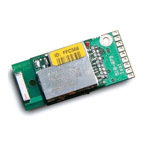
The DSC (card) products are very similar to the DCell but in a
different physical form for mounting stand-alone or on a board
External connections are via header pins which can plug into
connectors, or be soldered to wires or into a host PCB DSC has an
open collector output and volt free digital input

Mantracourt Electronics Limited DCell & DSC MantraCAN User Manual
7
Some pplication Examples
Simple Distributed Measurement
Pressure loads are taken at a number of keys points in a manufacturing process, distributed over a large area
Each pressure sensor contains a DCell unit, and all the sensors are connected by a single cable carrying power and
CAN communications A central PC allows continuous display, monitoring and logging of all values from a central
control room This displays a control-panel and current display window, and logs information to an Excel
spreadsheet for future analysis
Further monitoring checks and displayed information can easily be added when required to the system where up to
127 ‘nodes’ can be installed
Low Cost Dedicated Weighing Station
A basic load cell weighing-pad device has a cable leading to a wall mounted weight display
Digital Load Cell
Load cell products are offered with a high-precision digital communications option
A DCell is fitted into the gauge pocket of each load cell in manufacture During product testing, each unit undergoes
a combined load test and temperature cycle Each unit is then programmed with individually calculated gain, offset,
linearity and temperature compensation tables All units perform to a very tight specification without the use of any
trimming components
High Reliability Load sensing
A road bridge has a dedicated load monitoring and active control computer system System calibration adjustments
are only established during construction, so sensors must be replaceable without recalibration
Each load monitoring point has a digital load cell fitted, with calibration values set during construction Self-
diagnostics aid detection of failures
When a failed load cell is replaced it will produce identical force measurements The old load cell set-up data
values are programmed into the separate user-level calibration store in the unit, to produce an identically
performing replacement
Load Balance Monitor
A lorry loading weighpoint monitors left/right load balance and sounds a warning if loading is too uneven for safety
A drive-on weighing platform is provided with load cells at each of four corners Each cell is wired to a DSC unit, and
these are cabled to a 3
rd
party LCD display and control unit, producing a complete turnkey system A digital I/O card
is wired to the same bus to control the warning alarm Application software running on the control unit provides a %
left/right balance readout with a graphical tipping display, and a total weight indication
The balance indication is calculated by comparing the different corner readings If it exceeds a programmed limit, a
command to the I/O card turns the relay on
Total weight is calculated by summing the individual results mathematically
Automatic re-zeroing occurs when the total is near zero for more than a few seconds
A control button enables a set-up mode for recalibration (protected by operator password), which displays individual
readings and total Corner compensation can be checked by observing the changing total as a weight is moved
around Simple button presses control two point recalibration for any cell

Mantracourt Electronics Limited DCell & DSC MantraCAN User Manual
8
Chapter 2 Getting Started with the Evaluation Kit
This chapter explains how to connect up a DCell/DSC for the first time and how to get it working For simplicity,
this chapter is based on the standard DCell/DSC Evaluation Kit, which contains everything needed to communicate
with a puck or card from your PC
It is advised that first time users wishing to familiarise themselves with the product use the Mantracourt Evaluation
Kit This provides a low cost, easy way to get started
If you do not have an Evaluation Kit, the instructions in this chapter mostly still apply, but you will need to wire up
the device (and possible bus-converter) and have some means of communicating with it
The Evaluation Kit
Contents
• An Evaluation PCB (DSJ1) which comprises of
• A 8 way screw connector for the strain gauge & Temperature sensor
• A 5 way screw connector for power & CAN comms
• A 9 way ‘D’Type for direct CAN (limited to 500Kbps)
• Link headers for CAN, RS232 or RS485 comms selection
• Terminating resistor for CAN & RS485
• LED for power indication
• LED for digital output (DSC only)
• Push Switch for digital input (DSC only)
• An Evaluation DCell or DSC of your choice
• A CD ROM containing Instrument Explorer software
• A 9 way ‘D’Type extension lead
• A USB-CAN converter
• DTEMP temperature sensor for temperature compensation evaluation
Other Things you will need
• A regulated power supply, capable of providing 5 6 –18V at 100mA
• A PC running Windows 98 or above, with a spare USB port and 45Mb free disk space
and, ideally
• A strain gauge, load cell or simulator, 350-5000 ohms impedance

Mantracourt Electronics Limited DCell & DSC MantraCAN User Manual
9
Checking the Device Type
For a DCell, the Product Code is one o the ollowing 2 types
DLCSMCAN
DLCHMCAN
Industrial Stability MantraCAN output
High Stability MantraCAN output
For a DSC card, the Product Code is one o the ollowing 2 types
DSCSMCAN
DSCHMCAN
Industrial Stability MantraCAN output
High Stability MantraCAN output
The CAN bus Identi ier ID o a New DCell/DSC device is actory set to 1
This can be changed if required but for ease of evaluating it is suggested that you use this default value
Connecting Up The Evaluation Kit
Power is supplied to the DSJ1 via the 5 way connector (J1) This is connected to a supply set between 5 6v and 18v
DC The red wire being positive and the black negative The CAN is connected using the 9 way D-type extension lead
to J3 and to the USB-CAN converter
Ensure LK1 & LK5 are set to “CAN/RS485” Fit LK2 which terminates the CAN bus
Switch on, the Green Power LED of the DSJ1 should be on
Initial Checks
With no load cell connected The LED of the DCell or DSC should flash OFF for 100ms every 0 5s
Note: If a Load cell is connected and there are no errors then the LED will Flash ON for 100mS then Off for the
above period This being the normal healthy state
Another check that the device is working okay is by noting the current drawn from the supply, this should be about
40mA
Instrument Explorer
Instrument Explorer is Mantracourts own communication interface for our range of standard products It provides
communications drivers for the DCell/DSC products A complimentary copy is provided on CD-ROM with the
DCell/DSC Evaluation Kit Instrument Explorer can also be downloaded from Mantracourts website
http://www mantracourt co uk/software/Instrument_Explorer
Instrument Explorer is a software application that enables communication with Mantracourt Electronics
instrumentation for configuration, calibration, acquisition and testing purposes
The clean, contemporary interface allows full customisation to enable your Instrument Explorer to be moulded to
your individual requirements
What Can Instrument Explorer Do?
•Save and restore customisable user workspace
•Read and Write individual instrument parameters
•Save and restore parameter configurations
•Log data to a window or file
•Perform calibration and compensation
•
Installing Instrument Explorer
Install the Instrument Explorer software by inserting the CD in the CD ROM drive This should start the ‘AutoRun’
process, unless this is disabled on your computer
(If the install program does not start of its own accord, run SETUP EXE on the CD by selecting ‘Run’ from the ‘Start
Menu’ and then entering D:\SETUP, where D is the drive letter of your CD-ROM drive)
The install program provides step-by-step instructions The software will install into a folder called
InstrumentExplorer inside the Program F les folder You may change this destination if required

Mantracourt Electronics Limited DCell & DSC MantraCAN User Manual 10
Shortcut icons can be created on your desktop and shortcut bar After installation you may be asked to restart the
computer This should be done before proceeding with communications
When given the option to install IXXAT CAN drivers ensure these are selected, which is the default
Running the Instrument Explorer Software
Having installed Instrument Explorer you can now run the application, which the rest of this chapter is based
around
From the Windows ‘Start’ button, select Programs, then Instrument Explorer or click on the shortcut on your
desktop
Instrument Explorer Icon
The application should open and look like the following screen shot Instrument Explorer Window
The layout of Instrument Explorers Window and child windows allows the user full customisation to their
requirements If the application show a different arrangement of child windows than the above screen shot then
using then load one of the default workspaces as follows:

Mantracourt Electronics Limited DCell & DSC MantraCAN User Manual
11
Click File on the menu and select Open Workspace From the file dialogue window select Layout – Standard.iew
This will ensure your application layout matches this document
A list of available instruments is displayed in the Select Instrument pane of Instrument Explorer Select the relevant
device by clicking on the required device icon under the MantraCAN heading
Instrument Settings
MantraCAN
•Select the ID The factory default is 1
•Select the baud rate to which the device is set The factory default is 500KB
•Select the ID type Default is 11Bit (standard)
•Now click the ‘OK’ button…
The above assumes factory defaults If your device is known to have different settings use these instead of the ones
stated above

Mantracourt Electronics Limited DCell & DSC MantraCAN User Manual
12
Viewing Device Data
The following main parameter list should now appear in the central pane
Instrument Explorer Parameter List
When an instrument has been selected from the Select Instrument Window this Parameter List window will become
populated
The parameters and commands which are available for the selected device will appear in this list in a structured
hierarchic manner enabling the user to expand or contract categories by clicking the and buttons on the left of
the list
There are four types of parameters and commands:
Read/write Numeric – These parameter values are displayed in the right
hand column and can be edited by clicking the value
The value can then be changed and pressing the Enter key or moving away
from the edited value will cause the new value to be written to the
device There are no checks on the data entered and it is up to the user
to enter the correct data
Read-Only – These parameter values are displayed ‘greyed out’ and
cannot be changed

Mantracourt Electronics Limited DCell & DSC MantraCAN User Manual
13
Read/write Enumerated – These parameters can only be changed by
selecting the new value from a drop down list
Clicking in the right hand column will display a down arrow button which
when clicked will display the parameter value options in a list
Note that all enumerated data (apart from on/off) will be displayed with
a numeric value, hyphen then the description of the value
The numeric value is the value of the parameter and the description is
just there to help
Commands – These commands have ‘Click to execute…’ displayed in the
right hand column Clicking here will display a button Click this to
issue the command to the device
As parameters are changed the communications traffic is displayed in the Traffic Pane
If any errors occur these will be shown in red in the Error Pane Once an error occurs it will need to be reset before
any more communications can take place Reset errors by either right-clicking the Error Pane and selecting Reset
Errors from the pop-up menu or select the Communications menu and click the Reset Errors item
To manually refresh the parameter list click the
button on the toolbar or select Sync Now from the Parameters
menu
Now you have successfully established communications with your evaluation device the next step is to perform a
simple calibration
Connecting a Load Cell
You can now connect a strain gauge bridge, load cell or simulator to the DCell/DSC
A suitable strain gauge should have an impedance of 350-5000ohms and (at least for now) a nominal output of
around 2 5mV/V

Mantracourt Electronics Limited DCell & DSC MantraCAN User Manual
14
DSJ1 Evaluation Board Sensor Connections
Next Instrument Explorer will set to automatically update dynamic parameters from the device so that
we can see values as SYS changing on the screen To do this either click the
button on the toolbar or
click on the Parameters menu and select the Auto Sync item Note that these options toggle so be sure
to leave your selection in the active state
From the Parameter List click the next to the System heading to expand this level The Parameter List should look
as follows:
This now exposes more levels that can be expanded as
required by clicking the next to the heading name
Dynamic values (such as SYS and SRAW) will now be updating in real-time from the device

Mantracourt Electronics Limited DCell & DSC MantraCAN User Manual
15
Once you have connected the load cell, you should see ‘believable’ output values, in the “SYS” parameter displayed
in the parameter list pane These values should correspond to mV/V assuming the device is in it’s factory default
state
For diagnostics the device has two sets of flags One being latched and held within the devices non volatile memory
(FLAG parameter), the other being dynamic and volatile (STAT parameter)
Instrument Explorer provides a simple method of displaying and resetting of individual flags although these are held
within the device in FLAG and STAT parameters
To quickly clear all the flags simply write zero to the FLAG parameter Now if no problems exist all flags should in
their off state
If any flags remain on then refer to Chapter 3 for flag definitions
Performing System Calibration
The values obtained so far are in mV/V units, these are factory calibrated and fixed to within about 0 1% accuracy
The device also contains two separate user-adjustable calibration parameter groups, these are termed Cell and
System Cell being used to convert from mV/V to a force and System to convert this force to required engineering
units We shall being using System for the following exercise where we rescale the output value to read in units of
your choice, and to calibrate precisely to your load cell / system hardware
Instrument Explorer provide ‘Wizards’ to allow quick and simple calibration operations to be undertaken without the
use of a calculator Wizards can be activated by simply selecting the required item from the Wizard menu
Since we are now calibrating at system level we have a choice of two calibration methods:
Sys Calibration Table – This technique is used when a manufacturers calibration document is available for the
connected strain gauge This normally gives mV/V to engineering unit values
Sys Calibration Auto – This technique is used when the input can be stimulated with real input values For example
you have access to test weight / forces
We will now describe each of these techniques with an example

Mantracourt Electronics Limited DCell & DSC MantraCAN User Manual
16
Sys Calibration Table
A 10 tonne load cell manufacturer gives the following data:
mV/V output Force
2 19053 10 tonne
-0 01573 0 tonne
Start the wizard by selecting Sys Calibration Table from the Wizard menu
Click the Next button and enter the low values as shown below

Mantracourt Electronics Limited DCell & DSC MantraCAN User Manual
17
Click the Next button and enter the high values as shown below
Click Next the following window will be displayed showing the calibrated SYS value which is dependent on the
current input values
The device is now calibrated However you may find SYS has been ‘clamped’ if the resultant SYS is greater than
SMAX or less than SMIN If this is the case then change these values to suitable limits In this example we may set
SMIN to –0 5 (tonne) and SMAX to 12 0 (tonne) This would then provide clamping of SYS to these values and also a
flags being set in FLAG and STAT
Sys Calibration Auto
Assume we require to calibrate for Kg output and we have available a known accurate 10 Kg and 100 Kg test
weights
Start the wizard by selecting Sys Calibration Auto from the Wizard menu

Mantracourt Electronics Limited DCell & DSC MantraCAN User Manual
18
Click Next
Apply the low known test weight and enter the required SYS value for this weight In this case it will be 10 as we
want the units of SYS to be Kg Click Next to continue
Apply the high known test weight and enter the required SYS value for this weight In this case it will be 100 Click
Next to continue

Mantracourt Electronics Limited DCell & DSC MantraCAN User Manual
19
The device is now calibrated However you may find SYS has been ‘clamped’ if the resultant SYS is greater than
SMAX or less than SMIN If this is the case then change these values to suitable limits In this example we may set
SMIN to –0 5 (Kg) and SMAX to 110 0 (Kg) This would then provide clamping of SYS to these values and also a flags
being set in FLAG and STAT
For detailed information about calibration calculations please refer to chapter 3
This manual suits for next models
1
Table of contents
Other Mantracourt Control Unit manuals
