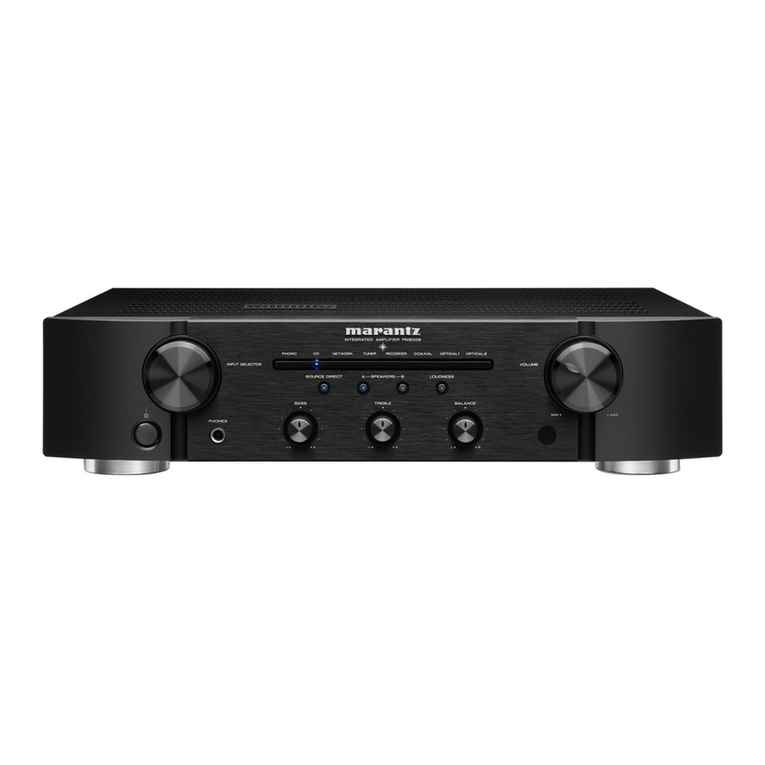
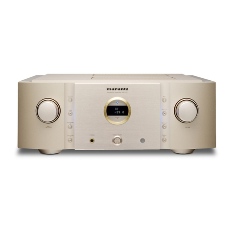
Marantz AV8003 User manual

AV Pre Tuner
AV8003
ENGLISHFRANÇAIS
AV8003UEng.indb3AV8003UEng.indb3 08.4.2810:40:02AM08.4.2810:40:02AM

CAUTION
RISK OF ELECTRIC SHOCK
DO NOT OPEN
CAUTION:TO REDUCETHE RISK OF ELECTRIC SHOCK,
DO NOT REMOVE COVER (OR BACK) NO USER-SERVICEABLE
PARTS INSIDE REFER SERVICINGTO QUALIFIED
SERVICE PERSONNEL
The lightning flash with arrowhead symbol within an equilateral triangle is
intended to alert the user to the presence of uninsulated “dangerous voltage”
within the product’s enclosure that may be of sufficient magnitude to constitute
a risk of electric shock to persons.
The exclamation point within an equilateral triangle is intended to alert the
user to the presence of important operating and maintenance (servicing)
instructions in the literature accompanying the product.
WARNING
TO REDUCE THE RISK OF FIRE OR ELECTRIC SHOCK,
DO NOT EXPOSE THIS APPLIANCE TO RAIN OR MOISTURE.
CAUTION: TO PREVENT ELECTRIC SHOCK, MATCH WIDE BLADE OF PLUG
TO WIDE SLOT, FULLY INSERT.
ATTENTION: POUR EVITER LES CHOCS ELECTRIQUES, INTRODUIRE
LA LAME LA PLUS LARGE DE LA FICHE DANS LA BORNE CORRESPON-
DANTE DE LA PRISE ET POUSSER JUSQU’AU FOND.
NOTETO CATV SYSTEM INSTALLER:
This reminder is provided to call the CATV (Cable-TV) system installer’s attention to Section 820-40 of the
NEC which provides guidelines for proper grounding and, in particular, specifies that the cable ground shall
be connected to the grounding system of the building, as close to the point of cable entry as practical.
NOTE:
This equipment has been tested and found to comply
with the limits for a Class B digital device, pursuant
to Part 15 of the FCC Rules. These limits are
designed to provide reasonable protection against
harmful interference in a residential installation.This
equipment generates, uses and can radiate radio
frequency energy and, if not installed and used in
accordance with the instructions, may cause harmful
interference to radio communications. However,
there is no guarantee that interference will not occur
in a particular installation. If this equipment does
cause harmful interference to radio or television
reception, which can be determined by turning the
equipment off and on, the user is encouraged to
try to correct the interference by one or more of the
following measures:
- Reorient or relocate the receiving antenna.
- Increase the separation between the equipment
and receiver.
- Connect the equipment into an outlet on a
circuit different from that to which the receiver is
connected.
- Consult the dealer or an experienced radio/TV
technician for help.
NOTE:
Changes or modifications may cause this unit to fail
to comply with Part 15 of the FCC Rules and may
void the user's authority to operate the equipment.
DECLARATION OF CONFORMITY
U.S. Responsible Party: Marantz America, Inc.
100 Corporate Drive,
Mahwah, NJ, 07430, U.S.A.
TEL: 201-762-6500
Type of Product:
Model:
AV Pre Tuner
AV8003
This device complies with Part 15 of the FCC rules. Operation is subject to the
following conditions: (1) This device may not cause harmful interference, and (2) this
device must accept any interference received, including interference that may cause
undesired operation.
This Class B digital apparatus complies with
Canadian ICES-003. Cet appareil numerique de la Classe B est conforme
a la norme NMB-003 du Canada.
AV8003UEng.indb4AV8003UEng.indb4 08.4.2810:40:02AM08.4.2810:40:02AM

Additional Safety Information!
• This product should not be placed in a built-in installation such as a bookcase or rack unless proper
ventilation is provided or the manufacturer’s instructions have been adhered to.
• Apparatus shall not be exposed to dripping or splashing and that no objects filled with liquids, such as
vases, shall be placed on the apparatus.
• When the switch is in the OFF position, the apparatus isn’t completely switched-off from the MAINS.
• The equipment shall be installed near the power supply so that the power supply is easily accessible.
• Do not touch hot spots during and immediately after use.
• During and immediately after use, this product is hot in areas other than the controls and rear panel
connection jacks.Do not touch hot spots and especially the top panel. Contact with hot areas can cause
burns.
• Do not be exposed to excessive heat such as sunshine, fire or the like.
IMPORTANT SAFETY
INSTRUCTIONS
READ BEFORE OPERATING EQUIPMENT
This product was designed and manufactured to meet strict quality and safety standards.
There are, however, some installation and operation precautions which you should be particularly aware of.
1. Read these instructions.
2. Keep these instructions.
3. Heed all warnings.
4. Follow all instructions.
5. Do not use this apparatus near water.
6. Clean only with dry cloth.
7. Do not block any ventilation openings.Install in accordance with the manufacture's instructions.
8. Do not install near any heat sources such as radiators, heat registers, stoves, or other apparatus
(including amplifiers) that produce heat.
9. Do not defeat the safety purpose of the polarized or grounding-type plug.A polarized plug has two
blades with one wider than the other. A grounding type plug has two blades and a third grounding
prong.The wide blade or the third prong are provided for your safety.If the provided plug does not fit
into your outlet, consult an electrician for replacement of the obsolete outlet.
10. Protect the power cord from being walked on or pinched particularly at plugs, convenience
receptacles, and the point where they exit from the apparatus.
11. Only use attachments/accessories specified by the manufacturer.
12. Use only with the cart, stand, tripod, bracket, or table specified by the manufacturer, or sold with the
apparatus.When a cart is used, use caution when moving the cart/apparatus combination to avoid
injury from tip-over.
13. Unplug this apparatus during lightning storms or when unused for long periods of time.
14. Refer all servicing to qualified service personnel. Servicing is required when the apparatus has been
damaged in any way, such as power-supply cord or plug is damaged, liquid has been spilled or
objects have fallen into the apparatus, the apparatus has been exposed to rain or moisture, does not
operate normally, or has been dropped.
AV_071203U2
AV8003U00cover.indd5AV8003U00cover.indd5 08.4.3010:57:49AM08.4.3010:57:49AM

ENGLISH
1
INTRODUCTION
Thank you for purchasing the Marantz AV8003 AV Pre tuner.
This remarkable component has been engineered to provide you with many years of home theater enjoyment.Please take a few minutes to read this manual thoroughly
before you connect and operate the AV8003.
As there are a number of connection and configuration options, you are encouraged to discuss your own particular home theater setup with your Marantz A/V specialist
dealer.
ACCESSORIES CHECK
Before use, check the below accessories were included in the package.
Remote Controller RC2001
AAA-size Alkaline batteries × 4
Remote Controller RC101 for Zone
AAA-size Dry batteries × 2
Microphone
AM Loop Antenna
FM Feeder Antenna
FM Antenna converter
USB cable for RC2001
AC power cable
AV8003 User Guide
AV8003 NETWORK User Guide
Wizz.it3 User Guide
Warranty Card
USA ×1
Canada ×1
AV8003U01ENG14.indd1AV8003U01ENG14.indd1 08.4.3010:58:25AM08.4.3010:58:25AM

CONNECTIONS SETUP BASIC
OPERATION
ADVANCED
OPERATION
REMOTE
CONTROLLER
TROUBLESHOOTING
OTHERS
NAMES AND
FUNCTION
ENGLISH
2
TABLE OF CONTENTS
BASIC OPERATION ............................39
SELECTING AN INPUT SOURCE...................................39
SELECTING THE SURROUND MODE...........................39
DIALOGUE NORMALIZATION MESSAGE.....................39
NIGHT MODE...................................................................39
ADJUSTING THE MAIN VOLUME ..................................40
ADJUSTING THE TONE (BASS & TREBLE) CONTROL..
40
TEMPORARILY TURNING OFF THE SOUND .................40
USING THE SLEEP TIMER .............................................40
M-DAX (Marantz Dynamic Audio eXpander) ...................40
VIDEO CONVERT............................................................40
CONPONENT I/P .............................................................41
HDMI RESOLUTION........................................................41
SURROUND MODE .............................41
ADVANCED OPERATION....................45
DISPLAY MODE ...............................................................45
RECORDING AN ANALOG SOURCE.............................45
SELECTING ANALOG AUDIO INPUT OR DIGITAL AUDIO
INPUT ..............................................................................45
LISTENING THROUGH HEADPHONES
.........................45
DOLBY HEADPHONE MODE .........................................46
ATTENUATION TO ANALOG INPUT SIGNAL ................46
7.1 CH INPUT...................................................................46
AUX INPUT.......................................................................47
VIDEO ON/OFF................................................................47
TV AUTO ON/OFF FUNCTION........................................47
LIP.SYNC ..........................................................................47
DUAL BACKUP MEMORY...............................................47
TUNER OPERATION ...........................48
TO SELECTING THE TUNER .........................................48
LISTENING TO THE TUNER...........................................48
PRESET MEMORY ..........................................................49
FOR LISTENING TO HD Radio STATIONS ...................52
RBDS OPERATION..........................................................54
XM RADIO OVERVIEW ...................................................55
LISTENING TO XM SATELLITE RADIO..........................56
SEARCH MODE...............................................................57
PRESET MEMORY ..........................................................58
INTRODUCTION ....................................1
ACCESSORIES CHECK....................................................1
TABLE OF CONTENTS .........................2
FEATURES.............................................2
BEFORE USE.........................................3
OPERATION OF REMOTE CONTROLLER......................4
NAMES AND FUNCTION ......................5
FRONT PANEL...................................................................5
FL DISPLAY AND INDICATER...........................................6
REAR PANEL .....................................................................7
REMOTE CONTROLLER RC2001....................................8
RC2001 LCD INDICATORS...............................................8
REMOTE CONTROLLER RC101......................................9
CONNECTIONS ...................................10
SPEAKER PLACEMENT .................................................10
CONNECTION TO AN MM8003 (BALANCED)...............11
CONNECTION TO AN MM8003 (UNBALANCED)..........11
CONNECTING AUDIO COMPONENTS..........................12
CONNECTING VIDEO COMPONENTS..........................13
CONNECTING HDMI COMPONENTS............................14
CONNECTING MULTI CHANNEL AUDIO COMPONENTS
..15
CONNECTING THE REMOTE CONTROL JACKS.........15
CONNECTING THE ANTENNA TERMINALS .................16
CONNECTING THE SATELLITE RADIO ........................17
CONNECTING FOR THE ZONE .....................................18
CONNECTING FOR SPEAKER C USE (BI-AMP CONNECTION)
..19
CONNECTIONS WITH NETWORK DEVICES................20
CONNECTING OTHER EQUIPMENT.............................20
SETUP ..................................................21
ONSCREEN DISPLAY MENU SYSTEM .........................21
1 INPUT SETUP .............................................................23
2 SPKR (SPEAKER) SETUP ..........................................26
ERROR MESSAGES .......................................................29
3 SURROUND SETUP ...................................................32
4 VIDEO SETUP .............................................................34
5 PREFERENCE ............................................................35
6 ACOUSTIC EQ ............................................................37
7 NETWORK SETUP ......................................................38
SIRIUS RADIO OVERVIEW.............................................60
LISTENING TO SIRIUS SATELLITE RADIO...................60
SEARCH MODE...............................................................62
PRESET MEMORY ..........................................................63
PARENTAL LOCK.............................................................64
ZONE SYSTEM....................................66
ZONE PLAYBACK USING THE ZONE OUT TERMINALS
...66
ZONE PLAYBACK USING THE SURROUND BACK
PREOUT TERMINALS.....................................................66
CONTROLLING THE ZONE FUNCTION FROM
ANOTHER ZONE.............................................................67
REMOTE CONTROLLER OPERATION
..69
GENERAL INFORMATION OF RC2001 TO THE UNIT..69
CONTROLLING MARANTZ COMPONENTS .................72
CONTROLLING ZONES USING THE RC2001 ..............80
BASIC OPERATION.........................................................82
MAIN MENU .....................................................................82
GENERAL INFORMATION OF RC101 TO THE UNIT....89
CONTROLLING MARANTZ COMPONENTS .................89
BASIC OPERATION.........................................................92
OTHER OPERATIONS.....................................................94
SETUP CODES (RC101) .................................................95
TROUBLESHOOTING .........................97
HDMI.................................................................................98
XM SATELLITE RADIO....................................................98
SIRIUS SATELLITE RADIO .............................................98
HD Radio RECEPTION....................................................98
OTHERS .............................................100
TECHNICAL SPECIFICATIONS ....................................100
DESCRIPTION ...............................................................101
FEATURES
This unit incorporates the latest generation of digital
surround sound decoding technology such as Dolby
Digital EX, Dolby Digital, DTS ES (Discrete 6.1 and
Matrix 6.1), DTS Neo:6 (Cinema, Music), Dolby Pro-
Logic II (Movie, Music and Game), Dolby Pro-Logic
IIx (Movie, Music and Game), Circle Surround II
(Cinema, Music and Mono).
Additionally, the unit is compatible with DolbyTrueHD
and DTS-HD (as used for Blu-ray and HD DVD discs)
as well as Dolby Digital Plus, an expanded and
improved version of Dolby Digital positioned as the
next-generation delivery format.These audio formats
can be sent with video signals via an HDMI cable to
HDMI 1.3a-compatible equipment.
In addition, Marantz has focused on the future. By
utilizing pre-out jacks, 7.1 direct inputs and a RS-232C
communication port, the unit is tomorrow’s technology,
today!
•THX ultra 2 certified
This unit incorporates the most advanced Digital
SignalProcessingcircuitry,alongwitha192kHz/24bit
D/A converter in each of the 7 channels.Independent
power supply circuits are incorporated for the FL
display, audio and video sections for maximum
separation, clarity and dynamic range.Together with
hand-selected customized components, all elements
work in harmony to recreate the emotion, exactly as
the artist had intended.
This unit is designed and engineered with extensive
feedback from custom installation experts, dealers
and consumers. It features zone/multisource,
assignable DC trigger, a RS-232C communication
port, Flasher input and an extensive array of both
analog and digital inputs / outputs.With 6 assignable
digital inputs, 4 component inputs, Super Audio CD
Multi Channel (7.1 channel) direct inputs, video
convert system and OSD output versatility is taken
to a stunning new level. Furthermore, the unit can
output the OSD information through the Y/C (S-
video) and composite video outputs.
An easy-to-use programmable, learning remote
controller allows full access to all of the operating
functions and can be used for system operation as
well.
The new generation of Marantz Receivers is stylish and
completely symmetrical. On the front panel of the unit,
buttons are kept to a minimum. Source selectors and
volume controls are intuitively placed.
This unit is here to perform in your unrivaled home
entertainment setup.
AV8003UEng.indb2AV8003UEng.indb2 08.4.2810:40:03AM08.4.2810:40:03AM
ENGLISH
3
• HDMI
HDMI (High-Definition Multimedia Interface) is an
enhancement to the DVI (Digital Visual Interface)
standard. It adds capabilities for digitally transmitting
audio signals in addition to video signals. Where
multiple cables were previously needed for audio/
video, HDMI enables audio/video connection via a
single cable.
The HDMI input jacks of this unit support HDMI Ver.
1.3a. and the HDMI output jacks of this transmitter
support HDMI Ver. 1.3a.
Copyright Protection
This unit supports HDCP (High-bandwidth Digital
Content Protection). HDCP is copyright protection
technology that consists of data encoding and other
device authentication.Its purpose is to protect digital
video content. Both this unit and the connected
component (such as a video player or monitor) must
support HDCP. Before connecting a component to
this unit, refer to its instruction manual.
• x.v.Color
• Deep Color 36bit
• THX / THX Surround EX
• Dolby True HD, Dolby Digital Plus, dts HD
• Dolby Digital EX, Dolby Digital, DTS ES
(Discrete 6.1, Matrix 6.1, Neo:6)
• Dolby Headphone
• Dolby Pro Logic II (Movie, Music, Game)
• Dolby Pro Logic IIx (Movie, Music, Game)
• Circle Surround II (Cinema, Music, Mono)
• HDCD
• Balanced Preout Terminal
• Balanced CD/CDR input terminal
• Bi-amp Pre out
• Source/Pure Direct mode
• 9 bands x 7 ch GEQ
• DSD to PCM converter
• Audyssey MultEQ
• M-DAX (Marantz Dynamic Audio eXpander)
• XM Satellite Radio Ready
• XM®HD Surround Powered by Neural Audio
• SIRIUS Satellite Radio Ready
• HD Radio
• Improved Station Name Input Method, 60 Presets
• AutoAdjustFunctionforSpeakerDistanceSettings
(Delay Time)
• Assignable DC Trigger Output
• Assignable Video Input
• Auto Lipsync (Audio Delay)
• Massive Energy Power Supply
• Troidal Core Transformer
• Function Rename
• 192 kHz/24 bit DAC for all 8 Channels
• 32 bit Digital Surround Processing Chipsets
• Auto Input Signal Detection
• Zone B output
• Up-scaling to full HD HDMI out from analog video
(480i/480p/576i/576p)
• Video Off Mode
•
Set Up Menu via allVideo Output
(Composite, S-Video, Component video and
HDMI)
• Video convert system
HDMI ←Component Video ↔
S-Video ↔Composit Video
• Two component monitor outputs
• Video I/P Converter
• Selectable Zone Component Video output
• RS-232C Terminal for Future Upgrade or System
Control
• Emitter Output
• Programmable, learning remote controller
• Customize RC2001 by using Wizz.it3 software
• Flasher Input
• IR Recever Input
• Allows playback of music, photos, and movies
stored on a network device.
BEFORE USE
This section must be read before any connection is
made to the mains supply.
EQUIPMENT MAINS WORKING SETTING
Your Marantz product has been prepared to comply
with the household power and safety requirements
that exist in your area.
AV8003 can be powered by 120V AC only.
COPYRIGHT
Recording and playback of any material may
require consent. For further information refer to the
following:
— Copyright Act 1956
— Dramatic and Musical Performers Act 1958
— Performers Protection Acts 1963 and 1972
—
Any subsequent statutory enactments and orders
DO NOT LOCATE IN THE FOLLOWING PLACES
To ensure long-lasting use, do not locate the unit where:
• Exposed to direct sunlight.
• Near to sources of heat such as heaters.
• Highly humid or poorly ventilated.
• Dusty.
• Subjected to mechanical vibrations.
•
On wobbly, inclined or otherwise unstable surfaces
• Radiated heat is blocked such as in cramped
audio racks.
• Make a space of about 8 inchs (0.2 m) around the
unit.
To ensure proper heat radiation, ensure the below
clearance from walls and other equipment.
TOP
TOP
ZONE
ZONE
SPEAKER
SPEAKER
DISPLAY
DISPLAY
INPUT
INPUT
7.1CH
7.1CH
DIRECT
DIRECT
PURE
PURE
PHONES
PHONES
THX
THX
M-DAX
M-DAX
MODE
MODE
SURROUND
SURROUND
CLEAR
CLEAR
MEMORY
MEMORY
T-MODE
T-MODE
BAND
BAND
EXIT
EXIT
MENU
MENU
ZONE
ZONE
DOWN
DOWN
VOLUME
VOLUME
UP
UP
INPUT
INPUT
SELECTOR
SELECTOR
AUTO
AUTO
SETUPMIC
SETUPMIC
HDMI
HDMI
M-DAX
M-DAX
PUREDIRECT
PUREDIRECT
POWERON/OFF
POWERON/OFF
STANDBY
STANDBY
AVPRETUNER AV8003
AVPRETUN ER AV8003
ENTER
ENTER
Left
8 inchs (0.2 m)
or more
Above
8 inchs (0.2 m)
or more
Right
8 inchs (0.2 m)
or more
Rear
8 inchs (0.2 m)
or more
KEEP OBJECTS OFF
Keep objects off the unit.Blocking the vent can result
in accident and damage.
DO NOT TOUCH HOT SPOTS DURING AND
IMMEDIATELY AFTER USE
During and immediately after use, the unit is hot
in areas other than the controls and rear panel
connection jacks. Do not touch hot spots and
especially the top panel. Contact with hot areas can
cause burns.
Opening and closing the front panel door
When you want to use the controls behind
the front panel door, open the door by gently
pressing on the lower part of the panel.Keep the
door closed when not using these controls.
Caution:
• Be careful not to pinch your fingers between the
door and the panel.
AV8003UEng.indb3AV8003UEng.indb3 08.4.2810:40:03AM08.4.2810:40:03AM
ENGLISH
4
OPERATION OF REMOTE CONTROLLER
REMOTE CONTROL
Operate the remote controller within a distance
of approx. 16.4 ft. (5m) from the infrared receptor
window on the front of the unit.
Remote controller
60°
Approx. 16.4 ft. (5 m)
Caution:
• Do not allow direct sunlight, an inverter fluorescent
light or other strong source of light to shine onto
the unit’s infrared receptor window. Otherwise,
the operation of the remote controller may be
disabled.
• Bear in mind that operating the remote controller
may cause other devices operated by infrared rays
to be operated by mistake.
• The remote controller cannot be operated if
the space between the controller and the unit’s
infrared receptor window is obstructed.
• Do not place any objects on top of the remote
controller.
Doing so may cause one or more buttons to be
held down which will cause the batteries to run
down.
LOADING BATTERIES
Before using the remote controller for the first time,
load the batteries in the remote controller. The
batteries provided are used to verify the operations
of the remote controller only.
<RC2001>
1. Remove the back cover.
2. Insert the new alkaline batteries (AAA type)
with correct ªand ·polarity.
3. Close the battery cover until it clicks shut.
Notes:
• Under normal usage, alkaline batteries last
approximately 3 months.
The battery life varies depending on the frequency
of use and the remote controller settings.Frequent
use will wear down the batteries quicker.
Rechargeable batteries can also be used. In this
case, be sure to use only AAA type NiMH (Nickel
Metal Hydride) rechargeable batteries. When
using rechargeable batteries, be sure to follow
manufacturer guidelines for safety and proper
usage.
• When the batteries are almost worn out, “LOW”is
displayed on the LCD battery indicator.
• The settings remain saved in the remote controller
even if the power completely runs out. However,
the time setting will be lost, and so please set the
time setting again.
<RC101>
1. Remove the battery cover.
2. Insert the new batteries (AAA type) with correct
ªand ·polarity.
3. Close the battery cover until it clicks shut.
Note:
• The life of the batteries used with the remote
controller is about 4 months with normal use.
CAUTIONS ON BATTERIES
• Use “AAA” type batteries in this remote controller.
• We recommend that you use alkali batteries.
• If the remote controller does not operate from
close to the unit, replace the batteries with new
ones, even if less then a year has passed.
• The included battery is only for verifying operation.
Replace it with a new battery as soon as possible.
• When inserting the batteries, be careful to do so in
the proper direction, following the + and - marks in
the remote controller’s battery compartment.
• To prevent damage or battery fluid leakage:
- Do not use a new battery with an old one.
- Do not use two different types of batteries.
- Do not short-circuit, disassemble, heat or
dispose of batteries in flames.
• Removethe batterieswhen notplanningto usethe
remote controller for a long period of time.
• If the batteries should leak, carefully wipe off the
fluid from the inside of the battery compartment,
then insert new batteries.
• When disposing of used batteries, please comply
with governmental regulations or environmental
public instruction’s rules that apply in your country
or area.
AV8003UEng.indb4AV8003UEng.indb4 08.4.2810:40:04AM08.4.2810:40:04AM

CONNECTIONS NAMES AND
FUNCTION
SETUP
BASIC
OPERATION
ADVANCED
OPERATION
REMOTE
CONTROLLER
TROUBLESHOOTING
OTHERS
ENGLISH
5
t
PURE DIRECT button and indicator
When this button is pressed once, “SOURCE
DIRECT”appears on the FL display.If pressed again,
“PURE DIRECT” appears. After 2 seconds, the FL
display indication goes out.
In the source/pure direct mode, the tone control
circuitry and bass management are bypassed.
Notes:
• The surround mode is automatically switched to
AUTO when the pure direct function is turned on.
• Additionally, speaker configurations are fixed
automatically as follows.
Front SPKR = LARGE
Center SPKR = LARGE
Surround SPKR = LARGE
Surround Back SPKR = LARGE
Sub woofer = YES
yZONE button
Press this button to activate the Zone system.
“MULTI” indicator will be illuminated in the display.
(See page 66)
uZONE SPEAKER button
Press this button to activate the Zone Speaker
system. “MULTI” indicator will be illuminated in the
display.
(See page 66)
qPOWER switch and STANDBY
indicator
When this switch is pressed once, the unit turns ON
and the display illuminates.When pressed again, the
unit turns OFF and the STANDBY indicator will be
illuminated.
wINPUT SELECTOR knob
(AUDIO/VIDEO)
This knob is used to select the input sources. (See
page 39)
eSURROUND MODE button
Press this button to select the surround mode.
rAUTO (Auto surround) button
Press this button to select the AUTO mode from the
surround modes. When this mode is selected, the
unit determines the surround mode corresponding to
a digital input signal automatically.
iMENU button
Press this button to enter the SETUP MAIN MENU.
oEXIT button
Press this button to exit from the SETUP MAIN
MENU.
!0 BAND button
Press this button to switch between FM, AM, XM (XM
Ready) and SIRIUS (SIRIUS Ready) in the TUNER
mode.
!1 T-MODE button
Press this button to select the auto stereo mode or
mono mode when the FM band is selected.
The “AUTO” indicator lights in the auto stereo mode.
(See page 49)
!2
INFRARED receiving sensor window
This window receives infrared signals for the remote
controller.
!3 MEMORY button
Press this button to enter the tuner preset memory
numbers or station names.(See page 49)
!4 CLEAR button
Press this button to cancel the station-memory
setting mode or preset scan tuning.(See page 50)
!5 VOLUME control knob
This knob is used to adjust the overall sound level.
Turning the control clockwise increases the sound
level.
!6 DISPLAY button
Press this button to change the FL display mode.
!7 M-DAX button
Press this button to select M-DAX processing for
input source.(See page 40)
!8
TOP button
Press this button to return to the top screen of the
main menu when configuring setup items.
(See page 21)
Also, press this button to return to the top screen of
the network when using the network.
!9
Cursor (
5, ∞, 2, 3
) / ENTER button
Press these buttons to operate the SETUP MAIN
MENU, NETWORK and TUNER function.
@0 7.1CH INPUT button
Press this button to select the output of an external
multichannel player.
@1 MIC jack
Automatically measure speaker characteristics using
the included microphone.(See page 27)
@2 THX button
Press this button to select THX processing for input
source.
@3
HEADPHONE jack for stereo headphones
This jack may be used to listen to the unit’s output
through a pair of headphones. Be certain that the
headphones have a standard 1/4” stereo phono
plug.
NAMES AND FUNCTION
TOP
TOP
ZONE
ZONE
SPEAKER
SPEAKER
DISPLAY
DISPLAY
INPUT
INPUT
7.1CH
7.1CH
DIRECT
DIRECT
PURE
PURE
PHONES
PHONES
THX
THX
M-DAX
M-DAX
MODE
MODE
SURROUND
SURROUND
CLEAR
CLEAR
MEMORY
MEMORY
T-MODE
T-MODE
BAND
BAND
EXIT
EXIT
MENU
MENU
ZONE
ZONE
ENTER
ENTER
DOWN
DOWN
VOLUME
VOLUME
UP
UP
INPUT
INPUT
SELECTOR
SELECTOR
AUTO
AUTO
SETUP MIC
SETUP MIC
HDMI
HDMI
M-DAX
M-DAX
PURE DIRECT
PURE DIRECT
POWER ON/STANDBY
POWER ON/STANDBY
STANDBY
STANDBY
AV PRE TUNER AV8003
AV PRE TUNER AV8 003
q tyu i o !0 !1 !3!4r!2 !5ew
!6
!7!8@0@1@3 !9@2
FRONT PANEL
AV8003U01ENG14.indd5AV8003U01ENG14.indd5 08.4.3010:58:37AM08.4.3010:58:37AM

CONNECTIONS
NAMES AND
FUNCTION SETUP BASIC
OPERATION
ADVANCED
OPERATION
REMOTE
CONTROLLER
TROUBLESHOOTING
OTHERS
ENGLISH
6
FL DISPLAY AND INDICATER
DISP MULTI AUTO TUNED ST V
–
OFF NIGHT PEAK ANALOG
DIGITAL
ATT
SLEEP SURR
AUTO DISC 6.1DIRECT MTX 6.1
DIGITAL
SURROUND
PCM
L
C
R
SL S SR
LFE
EQ
M-DAX
M-DAX
¡8
g
s
a
¡9 ¡7 ¡5™0 ¡6
h k l ¡1 ¡3f
j ¡0¡2 ¡4d
™1
aDISP (Display Off) indicator
This indicator is illuminated when this unit is in the
display off mode.
sSLEEP timer indicator
This indicator is illuminated when the sleep timer
function in the main-zone is in use.
dMULTI (Zone system) indicator
This indicator is illuminated when the zone system
is active.
fAUTO SURR
(Auto Surround mode) indicator
This indicator is illuminated to show that the AUTO
SURROUND mode is in use.
gTUNER’s indicators
AUTO : This indicator illuminates when the
tuner’s Auto mode is in use.
TUNED : This indicator illuminates when the
tuner receives a sufficiently strong
radio signal.
ST(Stereo) : This indicator illuminates when an
FM station is being tuned into stereo
condition.
h
DTS-ES mode indicators (DISC6.1, MTX6.1)
These indicators will illuminate to show the DTS-ES
decoding mode (Discrete 6.1 or Matrix 6.1).
jV (video)-OFF mode indicator
This indicator is illuminated when the Video-OFF
function is active.
kNIGHT mode indicator
This indicator is illuminated when this unit is in the
Night mode, which reduces the dynamic range of
digital program material at low volume levels.
lPEAK indicator
This indicator is a monitor for an analog audio input
signal. If the selected analog audio input signal is
greater than the capable level of internal processing,
this will illuminate. If this happens, you should press
the ATT button.(See page 70)
¡0 EQ indicator
This indicator is illuminated when the EQ MODE is
selected to “AUDDYSSEY”, “FRONT” or “FLAT”.
¡1 ATT (Attenuation) indicator
This indicator is illuminated when the attenuation
function is active.
¡2 DIGITAL Input Indicator
This indicator is illuminated when a digital input has
been selected.
¡3 ANALOG input indicator
This indicator is illuminated when an analog input
source has been selected.
¡4 SIGNAL FORMAT indicators
2DIGITAL
This indicator is illuminated when a Dolby Digital
signal is input.
EX
This indicator is illuminated when a Dolby Digital EX
signal is input.
dts
This indicator is illuminated when a DTS signal is
input.
ES
This indicator is illuminated when a DTS ES signal
is input.
96/24
This indicator is illuminated when a DTS 96/24 signal
is input.
PCM
This indicator is illuminated when the input signal is
PCM (pulse code modulation).
2SURROUND
This indicator is illuminated when a Dolby Surround
signal is input.
¡5 HDMI indicator
This indicator is illuminated when the HDMI device is
connected to the unit.
¡6
ENCODED CHANNEL STATUS indicators
These indicators display the channels that are
encoded with a digital input signal.
If the digital input signal is Dolby Digital 5.1ch or
DTS 5.1ch, “L”, “C”, “R”, “SL”, “SR” and “LFE” will be
illuminated.
If the digital input signal is 2 channel PCM-audio,“L”
and “R” will be illuminated.
If the digital input signal is 7.1 channel PCM-audio.
“L”, “C”, “R”, “SL”, “S” , “SR” and “LFE” will be
illuminated.
If the digital input signal is Dolby Digital 5.1ch signal
with Surround EX flag or DTS-ES, “L”, “C”, “R”, “SL”,
“S” , “SR” and “LFE” will be illuminated.
Note:
When the unit is decoding Dolby TrueHD, the input
signal status displayed depends on the number of
channels of the speakers used.
If a 7.1-channel signal is supplied for a 5.1-channel
speaker system (L/C/R/SL/SR/SW), the “S” indicator
is not illuminated.
¡7 HDCD indicator
This indicator is illuminated when the HDCD signal is
decoded from digital input signal.
¡8 Main Information Display
This display shows messages relating to the status,
input source, surround mode, tuner, volume level or
other aspects of unit’s operation.
¡9 DIRECT indicator
This indicator is illuminated when this unit is in the
SOURCE DIRECT mode. PURE DIRECT mode or
7.1ch input mode.
™0 M-DAX indicator
This indicator illuminates when this unit is in the M-
DAX mode.
™1 PURE DIRECT indicator
This indicator is illuminated when this unit is in the
PURE DIRECT mode.
AV8003UEng.indb6AV8003UEng.indb6 08.4.2810:40:04AM08.4.2810:40:04AM

CONNECTIONS NAMES AND
FUNCTION
SETUP
BASIC
OPERATION
ADVANCED
OPERATION
REMOTE
CONTROLLER
TROUBLESHOOTING
OTHERS
ENGLISH
7
yBALANCED PREOUT
(L, R,SL, SR, SBL, SBR, C)
ConnecttheL(frontleft),R(frontright), C (center), SL
(Surround left), SR (Surround right), SBL (Surround
back left), and SBR (Surround back right) terminals
to the balanced input terminals of a power amp such
as the MM8003.
uNETWORK
Connect to a network device such as a router or
hub.
This allows you to play back music, photos, and
movie files stored on a connected network device.
iSubwoofer Output
These are subwoofer outputs and each one includes
both unbalanced and balanced jack configulations.
Connect this jack to the line level input of a powered
subwoofer.
oSPEAKER C switch
Set to ON to connect a bi-amp to this unit or set to
OFF for normal connection (surround back and zone
speakers).(See page 19)
!0 SIRIUS terminal
Connect the SiriusConnect Home tuner.
See page 17 for connecting information.
!1 XM terminal
Connect the XM Mini Tuner and Home Dock.
See page 17 for connecting information.
!2 RS-232C
The RS-232C port is to be used in connectionwith an
external controller to control the operation of the unit
by using an external device.
The RS-232C port may also be used in the future to
update the operating software of the unit so that it will
be able to support new digital audio formats and the
like as they are introduced.
!3 AC INLET
Plug the supplied power cable into this AC INLET
and then into the power outlet on the wall.
This unit can be powered by 120V AC only.
!4 CD/CDR Input Selection Switch
Switches between BALANCED and UNBALANCED
for the CD/CDR IN terminals.
Notes:
• Always set the input selection before turning on the
power. Equipment failure may result If the input
selection is switched while the power is on.
• Audio may not be output from the main unit if the
input to the unit differs from the setting of the Input
Selection Switch.
!5 BALANCED CD/CDR IN
Connect to the balanced output terminal of a Super
Audio CD Player or similar player.
The UNBALANCED CD/CDR input terminals are
the CD/CDR IN terminals in @3.
Note:
Do not connect to the BALANCED and
UNBALANCED terminals at the same time.
!6 7.1 CHANNEL or AUX INPUT
By connecting a DVD Audio player, Super Audio CD
multichannel player, or other components that has a
multichannel port, you can playback the audio with
5.1 channel or 7.1 channel outputs.
!7 EMITTER OUT
The signals input to the IR RECEIVER IN terminals
are output to this terminal. External devices can be
controlled by connecting them to this terminal.
!8 IR RECEIVER IN
Connect to an external IR receiver.
!9
FLASHER IN (Flasher input terminal)
Theseterminalsare tocontrol the unitfrom eachzone.
Connect the control signal from a Keypad, etc.
@0 DCTRIGGER output terminal
Connect a device that needs to be triggered by DC
under certain conditions (screen, power strip, etc…)
Use the system OSD setup menu to determine the
conditions by which these jack will be active.
(See page 36)
Note:
• This output voltage is for (status) control only, It is
not sufficient for drive capability.
REAR PANEL
eZone Outputs
(Audio output A/B,Video)
These are the audio and video output jacks for the
Multi zone.
Connect these jacks to optional audio power
amplifiers or video display devices to listen and view
the source selected by the zone system in a remote
room.
rMONITOR OUT
These are monitor outputs and each one includes
both composite video and S-video configurations.
When connecting two video monitors or televisions,
be aware that the OSD interface can be used with
both MONITOR OUT connections.
tUNBALANCED PREOUT
(L, R, SL, SR, SBL, SBR, C)
ConnecttheL(frontleft),R(frontright), C (center), SL
(Surround left), SR (Surround right), SBL (Surround
back left), and SBR (Surround back right) terminals
to the unbalanced input terminals of a power amp
such as the MM8003.
qFM antenna terminal (75 ohms)
Connect an external FM antenna with a coaxial
cable, or a cable network FM source.
AM antenna and ground terminals
Connect the supplied AM loop antenna. Use the
terminals marked “AM” and “GND”.The supplied AM
loop antenna will provide good AM reception in most
areas. Position the loop antenna until you hear the
best reception.
wCOMPONENTVIDEO INPUT/
OUTPUT
If your DVD player or other device has component
video connectors, be sure to connect them to these
component video connectors on the unit. This unit
has 4 component video input connectors to obtain
the color information (Y, CB, CR) directly from the
recorded DVD signal or other video component and
two component video outputs connector to output it
directly into the matrix decoder of the display device.
By sending the pure DVD component video signal
directly, the DVD signal forgoes the extra processing
that normally would degrade the image.The result is
vastly increased image quality, with incredibly life like
colors and crisp detail.
The Monitor Out 2 terminal is also used for ZONE
output.
L
L
SR
SR
SL
SL
R
R
R
R
SR
SR
SL
SL
SW
SW
C
C
SBR
SBR
SBL
SBL
L
L
SBL
SBL
SW
SW
C
C
SBR
SBR
FM
FM
(
(
75
75
Ω
Ω
)
)
GND
GND
AM
AM
ANTENNA
ANTENNA
OUT
OUT
PUT
PUT
1
1
OUT
OUT
PUT
PUT
2
2
INPUT 3
INPUT 3
(
(
VCR1
VCR1
)
)
OUTPUT 1
OUTPUT 1
OUTPUT 2
OUTPUT 2
INPUT 1
INPUT 1
(
(
TV
TV
)
)
INPUT 4
INPUT 4
(
(
DSS/VCR2
DSS/VCR2
)
)
INPUT 2
INPUT 2
(
(
DVD
DVD
)
)
COMPONENT
COMPONENT
VIDEO
VIDEO
C
C
B
B
/
/
P
P
B
B
C
C
R
R
/
/
P
P
R
R
C
C
R
R
/
/
P
P
R
R
C
C
R
R
/
/
P
P
R
R
C
C
B
B
/
/
P
P
B
B
C
C
B
B
/
/
P
P
B
B
Y
Y
Y
Y
Y
Y
INPUT 1
INPUT 1
(
(
TV
TV
)
)
INPUT 4
INPUT 4
(
(
DSS
DSS
/
/
VCR2
VCR2
)
)
INPUT 3
INPUT 3
(
(
VCR1
VCR1
)
)
INPUT 2
INPUT 2
(
(
DVD
DVD
)
)
RS-232C
RS-232C
SPEAKER C
SPEAKER C
SIRIUS
SIRIUS
NETWORK
NETWORK
ON
ON
OFF
OFF
13
CONNECTION
GND
HOT(+)
COLD(
-
)
3
2
1
2
AC IN
AC IN
OUT
OUT
IN
IN
IN
IN
OUT
OUT
VIDEO
VIDEO
MONITOR
MONITOR
OUT
OUT
DVD
DVD
(
(
2
2
)
)
DSS/VCR2
DSS/VCR2
(
(
4
4
)
)
TV
TV
(
(
1
1
)
)
ZONE
ZONE
OUT
OUT
VCR1
VCR1
(
(
3
3
)
)
DVD
DVD
(
(
2
2
)
)
TV
TV
(
(
1
1
)
)
2
2
1
1
FLASHER
FLASHER
IN
IN
IR
IR
RECEIVER
RECEIVER
IN
IN
6
6
COAX.
COAX.
5
5
4
4
OUT
OUT
IN
IN
1
1
2
2
EMITTER
EMITTER
OUT
OUT
SELECTOR
SELECTOR
DC OUT
DC OUT
R
R
L
L
OUT
OUT
R
R
OUT
OUT
L
L
TAPE
TAPE
OUT
OUT
IN
IN
R
R
OUT
OUT
L
L
DSS/VCR2
DSS/VCR2
AUDIO
AUDIO
BALANCED
BALANCED
PRE OUT
PRE OUT
UNBALANCED
UNBALANCED
TV
TV
IN
IN
SR
SR
VCR1
VCR1
IN
IN
DVD
DVD
SL
SL
SBR
SBR
SBL
SBL
SW
SW
C
C
A
A
B
B
7.1CH
7.1CH
IN
IN
(
(
AUX
AUX
)
)
3
3
2
2
1
1
OPT.
OPT.
MODEL NO. AV8003
MODEL NO. AV8003
DIGITALIN
DIGITALIN
DIGITALOUT
DIGITALOUT
MAIN
MAIN
ZONE
ZONE
CD/CDR
CD/CDR
IN
IN
REMOTE
REMOTE
1
23
BALANCED
BALANCED
UNBALANCED
UNBALANCED
IN
IN
OUT
OUT
S-VIDEO
S-VIDEO
IN
IN
OUT
OUT
DSS/VCR2
DSS/VCR2
(
(
4
4
)
)
VCR1
VCR1
(
(
3
3
)
)
MONI. OUT
MONI. OUT
CD/CDR BALANCED IN
CD/CDR BALANCED IN
ZONE OUT
ZONE OUT
CONNECTION
GND
HOT(+)
COLD(
-
)
3
2
1
3
12
3
12
3
12
3
12
3
12
3
12
3
12
3
12
3
12
3
12
PUSH PUSH
q w t y
u
!3 i!6@1@2
e@0
o!0!2!1!5 !4!7!8!9
@3
@6
@4
@5
re
AV8003UEng.indb7AV8003UEng.indb7 08.4.2810:40:05AM08.4.2810:40:05AM

CONNECTIONS
NAMES AND
FUNCTION SETUP BASIC
OPERATION
ADVANCED
OPERATION
REMOTE
CONTROLLER
TROUBLESHOOTING
OTHERS
ENGLISH
8
@1
ZONE REMOTE IN/OUT terminals
IN: Connect to a zone remote control device,
available from your Marantz dealer.
OUT: Connect to the Marantz component equipped
with remote control (RC-5) terminals in Multi
zone.
@2 REMOTE CONT. IN/OUT terminals
Connect to a Marantz component equipped with
remote control (RC-5) terminals.
@3 AUDIO IN/OUT (TV, DVD,VCR1,
DSS/VCR2,TAPE, CD/CDR)
These are the analog audio inputs and outputs.
There are 6 audio inputs and 4 audio outputs. The
audio jacks are nominally labeled for cassette tape
decks, compact disc players, DVD players and etc....
The audio inputs and outputs require RCA-type
connectors.
@4 DIGITAL INPUT (Dig.1 - 6) /
OUTPUT (coaxial, optical)
These are the digital audio inputs and outputs.There
are 3 digital inputs with coaxial jacks, 3 with optical
jacks.
The inputs accept digital audio signals from a CD,
DVD, or other digital source component.
For digital output, there is 1 coaxial output and 1
optical output.
ThedigitaloutputscanbeconnectedtoMDrecorders,
CD recorders, or other similar components.
@5
VIDEO IN/OUT
(TV, DVD,VCR1, DSS/VCR2)
These are the video inputs and outputs. There
are 4 video inputs and 2 video outputs and each
one includes both composite video and S-video
configurations. Connect VCRs, DVD players, and
other video components to the video inputs.
The 2 video output channels can be used to be
connected to video tape recorders for making
recordings.
@6 HDMI INPUT / OUTPUT
This unit has 4 HDMI inputs and 2 HDMI output.The
input function can be selected from the OSD menu
system.(See page 24)
RC2001 LCD INDICATORS
A
B
C
D
AMode display area
Home:
This is displayed during Home mode.
Device Name:
This displays the device mode name that is currently
active.
This area is always highlighted.
BCommand display area
This displaysthe information that has been set for the
display items in the device modes.
CBattery indicator
This displays the remaining battery power.
DSub info. Area
Normal operation:
Thepage number thathasbeen set forthe respective
mode is displayed.
When sending IR command:
The command name that has been set for the
respective button is highlighted.
Operation when not sending an IR command
(such as jump operation):
The operation name that has been set for the button
is displayed normally (not highlighted).
REMOTE CONTROLLER RC2001
The provided remote controller is a universal remote
controller.The POWER button, numeric buttons and
control buttons are used in common across different
input source components.
You can use the Wizz.it3 editing software to select
your favorite settings for the buttons and pages of the
remote controller.
z
x
c
v
v
b
n
.
.m
,
⁄0
zPOWER ON and OFF buttons
These buttons are used when controlling devices
that have been set with separately powered on and
off remote commands.
xSOURCE ON/OFF button
This button is used when controlling devices that
have been set with a single power on/off remote
command.
cLCD Display
Remote controller display
vProgrammable soft buttons
These buttons are used by the Wizz.it 3 editor
software to make LCD display and button operation
settings.
These buttons are also used to adjust the number of
pages for each device.
bPage Scroll buttons
These buttons are used when scrolling pages in
Home mode and the device modes.
nHome button
This button is used to select Home mode.
To select a device that will be controlled, first select
Home mode, then select the device.
mLight button
This button is used to turn on the backlight for the
buttons and LCD.
,Cursor, ENTER buttons
.Programmable Hard buttons
These buttons are used by the Wizz.it 3 editor
software to make the remote controller command
settings for learning and macro operations.
⁄0 USB port
This port is used to connect the remote controllerand
a PC with the supplied USB cable to enable editing
with the Wizz.it 3 editor software.
AV8003UEng.indb8AV8003UEng.indb8 08.4.2810:40:05AM08.4.2810:40:05AM

CONNECTIONS NAMES AND
FUNCTION
SETUP
BASIC
OPERATION
ADVANCED
OPERATION
REMOTE
CONTROLLER
TROUBLESHOOTING
OTHERS
ENGLISH
9
REMOTE CONTROLLER RC101
The included remote controller can be used in zone
systems. Using this remote controller, you can
operate the unit through infrared receivers or the
infrared receptor of Marantz products in multiple
ZONEs. The SOURCE ON/OFF button and control
buttons are used in common across different input
source components.
The input source controlled withthe remote controller
changes when one of the input selector buttons is
pressed.
zPOWER ON and OFF buttons
(When Zone A/B mode is selected)
These buttons are used to turn on or off, for the
ZONE control or zone speaker control of the unit.
(When Zone D (MAIN ZONE) mode is selected)
These buttons are used to turn on or off, for the unit
in main zone.
xSOURCE ON and OFF buttons
These buttons are used to turn on or off a specific
source (such as a DVD player) independently from
the rest of the system.
(When NETWORK mode (AUX2) is selected)
SOURCE ON button
This button is used to select the screen resolution.
SOURCE OFF button
This button is used to return to the previous screen.
cAMP - SOURCE /Numeric buttons
SOURCE buttons
These buttons are used to switch the source of
the unit. Each time a source button is pressed, the
remote control changes to the source which was
pressed.
This remote controller can control 12 types of
equipment. To change the unit source, press this
button twice within two seconds. The signal is sent
when it is pressed the second time.
Notes:
• Press AUX2 to switch to NETWORK function.
• The T2 button is not used for this unit.
(When Zone A/B mode is selected)
These buttons are used to select the source for the
zone/zone speaker control of the unit.
(When Zone D (MAIN ZONE) mode is selected)
These buttons are used to select the source for the
unit in main zone.
Numeric buttons
Use these buttons only for preset setting.
vAMP -VOL +/- buttons
(When Zone A/B mode is selected)
These buttons are used to adjust the volume for the
zone control or zone speaker.
(When Zone D (MAIN ZONE) mode is selected)
These buttons are used to adjust the volume for the
unit in main zone.
z
⁄7
⁄6
⁄4
⁄5
⁄3
⁄2
x
c
v
b
n
m
,
.
⁄0
⁄1
bAMP - MUTE button
(When Zone A/B mode is selected)
This button is used to mute the audio for the zone
control or zone speaker control of the unit.
(When Zone D (MAIN ZONE) mode is selected)
These buttons are used to mute the audio for the unit
in main zone.
n3, 4, 1, 2(CURSOR) / ENTER
buttons
These buttons are used when operating cursor of a
source.
(WhenTuner mode (T1) is selected)
PRESET +/ PRESET - buttons
Used to select a preset station up and down.
TUNE 3/TUNE 4buttons
Used to tune a frequency station up and down.
mSLEEP button
(When Zone A/B mode is selected)
This button is used for setting the sleep timer of zone
control mode.
(When Zone D (MAIN ZONE) mode is selected)
This button is used for setting the sleep timer of the
unit receiver in main zone.
,CONTROL buttons
These buttons areused when operating PLAY, STOP,
PAUSE and other commands of a source.
(WhenTUNER mode (T1) is selected)
P.SCAN button
Used to start preset scan.
CLEAR button
Used to stop preset scan.
.A/B/C/D buttons
(WhenTUNER mode (T1) is selected)
Used to select the band of tuner (AM/FM).
Note:
The C (XM) and D (DAB) button are not used for
this unit.
(When the other source is selected)
Reserve key for the learning commands.
⁄0 SET button
This button is used to enter learn mode, preset mode
and clone mode.
⁄1 ZONE button
This button is used to set the zone area.
• Zone A
• Zone B
• Zone C (The unit does not use this zone.)
• Zone D (MAIN ZONE)
⁄2 DISC+/T.MODE
(WhenTUNER mode (T1) is selected)
Used to select auto stereo mode or mono mode
when the FM band is selected.
The “AUTO” indicator lights in the auto stereo mode.
(When CD/DVD/CDR mode is selected)
Used to change the disc for the CD/DVD/CDR
changer.
⁄3 INFO button
(When Zone A mode is selected)
When this button is pressed, the current setting for
selected zone control of the unit is displayed on the
TV monitor.
(When Zone D (MAIN ZONE) mode is selected)
When this button is pressed, the current setting for
the unit are displayed on the TV monitor.
⁄4 MENU/INPUT button
(When DVD mode is selected)
Used to menu command.
(WhenTV mode is selected)
Used to select the TV video input.
⁄5 CH 3/4buttons
These buttons are used to change channels in TV
mode and DSS mode.
⁄6 SEND indicator
Indicates when the remote controller is transmitting
a signal.
⁄7 LEARN indicator
Indicates when the remote controller is in the LEARN
mode.
AV8003UEng.indb9AV8003UEng.indb9 08.4.2810:40:05AM08.4.2810:40:05AM

SETUP BASIC
OPERATION
ADVANCED
OPERATION
REMOTE
CONTROLLER
TROUBLESHOOTING
OTHERS
NAMES AND
FUNCTION CONNECTIONS
ENGLISH
10
CONNECTIONS
SPEAKER PLACEMENT
The ideal surround speaker system for this unit is 7-
speaker systems, using front left and right speakers,
a center speaker, surround left and right speakers,
a surround back left and right speakers, and a
subwoofer.
Forbestresults we recommend that allfront speakers
be of the same type, with identical or similar driver
units. This will deliver smooth pans across the front
sound stage as the action moves from side to side.
Your center channel speaker is very important as
over 80 % of the dialog from a typical motion picture
emanates from the center channel.
It should possess similar sonic characteristics to the
main speakers.Surround channel speakers need not
be identical to the front channel speakers, but they
should be of high quality.
The surround center speaker is useful for playback
of Dolby Digital Surround EX or DTS-ES. One of
the benefits of both Dolby Digital and DTS is that
surround channels are discrete full range, while they
were frequency limited in earlier “Pro Logic” type
systems.
Bass effects are an important part of home theater.
For optimal enjoyment a subwoofer should be used
as it is optimized for lowfrequency reproduction.If you
have full range front speakers, however, they may be
used in place of a subwoofer with proper setting of the
switches in the menu system.
Surround Back Right
Front Right
Front Left
Front Center
Surround Left
Subwoofer
Surround Back Left
Surround Right
Front left and right speakers
We recommend to set the front L and R speakers
with 45-60 degrees from the listening position.
Center speaker
Align the front line of the center speaker with the front
L/R speakers. Or place the center speaker a little
backward from the line.
Surround left and right speakers
When this unit is used in surround operation, the
preferred location for surround speakers is on the
side walls of the room, at or slightly behind the
listening position.
The center of the speaker should face into the room.
Surround back left and right speakers
Surround back speakers are required when a full 7.1-
channel system is installed.
Speakers should be placed on a rear wall, behind the
listening position.
The center of the speaker should face into the room.
Subwoofer
We recommend using a sub-woofer to have maximum
bass effect.As the subwoofer only handle low frequency.
You can place it any where in the room.
HEIGHT OF THE SPEAKER UNITS
Front left and right speakers,and a center speaker
Align the tweeters and mid-range drivers on the
three front speakers at the same height, as best as
possible.
Surround left and right speakers, and surround
back speaker
Place the surround left, right and surround back
speakers higher than your ears by about 27-9/16
– 39-3/8 inchs (70cm–1m). Also place the speakers
at the same height, as best as possible.
27-9/16 39-3/8 inchs
(70cm 1m)
Note:
• Use magnetically-shielded speakers for front left,
right and the center speakers when the speakers are
installed near the TV.
AV8003UEng.indb10AV8003UEng.indb10 08.4.2810:40:06AM08.4.2810:40:06AM

SETUP
BASIC
OPERATION
ADVANCED
OPERATION
REMOTE
CONTROLLER
TROUBLESHOOTING
OTHERS NAMES AND
FUNCTION
CONNECTIONS
ENGLISH
11
CONNECTION TO AN MM8003 (BALANCED)
Connect the L (front left), R (front right), C (center), SL (Surround left), SR (Surround right), SBL (Surround
back left), and SBR (Surround back right) terminals to the balanced input terminals of a power amp such as
the MM8003.
CONNECTING A SUBWOOFER
Use the SW jack to connect a powered subwoofer (power amplifier built in ).
CONNECTION TO AN MM8003 (UNBALANCED)
Connect the L (front left), R (front right), C (center), SL (Surround left), SR (Surround right), SBL (Surround
back left), and SBR (Surround back right) terminals to the unbalanced input terminals of a power amp such
as the MM8003.
CONNECTING A SUBWOOFER
Use the SW jack to connect a powered subwoofer (power amplifier built in ).
L
L
SR
SR
SL
SL
R
R
R
R
SR
SR
SL
SL
SW
SW
C
C
SBR
SBR
SBL
SBL
L
L
SBL
SBL
SW
SW
C
C
SBR
SBR
FM
FM
(
(
75
75
Ω
Ω
)
)
GND
GND
AM
AM
ANTENNA
ANTENNA
OUT
OUT
PUT
PUT
1
1
OUT
OUT
PUT
PUT
2
2
INPUT 3
INPUT 3
(
(
VCR1
VCR1
)
)
OUTPUT 1
OUTPUT 1
OUTPUT 2
OUTPUT 2
INPUT 1
INPUT 1
(
(
TV
TV
)
)
INPUT 4
INPUT 4
(
(
DSS/VCR2
DSS/VCR2
)
)
INPUT 2
INPUT 2
(
(
DVD
DVD
)
)
COMPONENT
COMPONENT
VIDEO
VIDEO
C
C
B
B
/
/
P
P
B
B
C
C
R
R
/
/
P
P
R
R
C
C
R
R
/
/
P
P
R
R
C
C
R
R
/
/
P
P
R
R
C
C
B
B
/
/
P
P
B
B
C
C
B
B
/
/
P
P
B
B
Y
Y
Y
Y
Y
Y
INPUT 1
INPUT 1
(
(
TV
TV
)
)
INPUT 4
INPUT 4
(
(
DSS
DSS
/
/
VCR2
VCR2
)
)
INPUT 3
INPUT 3
(
(
VCR1
VCR1
)
)
INPUT 2
INPUT 2
(
(
DVD
DVD
)
)
RS-232C
RS-232C
SPEAKER C
SPEAKER C
SIRIUS
SIRIUS
NETWORK
NETWORK
ON
ON
OFF
OFF
13
CONNECTION
GND
HOT(+)
COLD(
-
)
3
2
12
AC IN
AC IN
OUT
OUT
IN
IN
IN
IN
OUT
OUT
VIDEO
VIDEO
MONITOR
MONITOR
OUT
OUT
DVD
DVD
(
(
2
2
)
)
DSS/VCR2
DSS/VCR2
(
(
4
4
)
)
TV
TV
(
(
1
1
)
)
ZONE
ZONE
OUT
OUT
VCR1
VCR1
(
(
3
3
)
)
DVD
DVD
(
(
2
2
)
)
TV
TV
(
(
1
1
)
)
2
2
1
1
FLASHER
FLASHER
IN
IN
IR
IR
RECEIVER
RECEIVER
IN
IN
6
6
COAX.
COAX.
5
5
4
4
OUT
OUT
IN
IN
1
1
2
2
EMITTER
EMITTER
OUT
OUT
SELECTOR
SELECTOR
DC OUT
DC OUT
R
R
L
L
OUT
OUT
R
R
OUT
OUT
L
L
TAPE
TAPE
OUT
OUT
IN
IN
R
R
OUT
OUT
L
L
DSS/VCR2
DSS/VCR2
AUDIO
AUDIO
BALANCED
BALANCED
PRE OUT
PRE OUT
UNBALANCED
UNBALANCED
TV
TV
IN
IN
SR
SR
VCR1
VCR1
IN
IN
DVD
DVD
SL
SL
SBR
SBR
SBL
SBL
SW
SW
C
C
A
A
B
B
7.1CH
7.1CH
IN
IN
(
(
AUX
AUX
)
)
3
3
2
2
1
1
OPT.
OPT.
MODEL NO. AV8003
MODEL NO. AV8003
DIGITALIN
DIGITALIN
DIGITALOUT
DIGITALOUT
MAIN
MAIN
ZONE
ZONE
CD/CDR
CD/CDR
IN
IN
REMOTE
REMOTE
1
23
BALANCED
BALANCED
UNBALANCED
UNBALANCED
IN
IN
OUT
OUT
S-VIDEO
S-VIDEO
IN
IN
OUT
OUT
DSS/VCR2
DSS/VCR2
(
(
4
4
)
)
VCR1
VCR1
(
(
3
3
)
)
MONI. OUT
MONI. OUT
CD/CDR BALANCED IN
CD/CDR BALANCED IN
ZONE OUT
ZONE OUT
CONNECTION
GND
HOT(+)
COLD(
-
)
3
2
1
PUSH PUSH
DC CONTROL
DC CONTROL
IN
IN
FLASHER
FLASHER
OUT
OUT
OUT
OUT
IN
IN
REMOTE CONTROL
REMOTE CONTROL
(
(
L
L
)
)
CHANNEL 1
CHANNEL 1
(
(
R
R
)
)
CHANNEL 2
CHANNEL 2
(
(
SL
SL
)
)
CHANNEL 3
CHANNEL 3
(
(
SR
SR
)
)
CHANNEL 4
CHANNEL 4
(
(
SBL
SBL
)
)
CHANNEL 5
CHANNEL 5
(
(
SBR
SBR
)
)
CHANNEL 6
CHANNEL 6
(
(
C
C
)
)
(
(
OPTION
OPTION
)
)
CHANNEL 7
CHANNEL 7
CHANNEL 8
CHANNEL 8
(
(
L
L
)
)
CHANNEL 1
CHANNEL 1
(
(
R
R
)
)
CHANNEL 2
CHANNEL 2
(
(
SL
SL
)
)
CHANNEL 3
CHANNEL 3
(
(
SR
SR
)
)
CHANNEL 4
CHANNEL 4
(
(
SBL
SBL
)
)
CHANNEL 5
CHANNEL 5
(
(
SBR
SBR
)
)
CHANNEL 6
CHANNEL 6
(
(
C
C
)
)
(
(
OPTION
OPTION
)
)
CHANNEL 7
CHANNEL 7
CHANNEL 8
CHANNEL 8
SPEAKER SYSTEMS
SPEAKER SYSTEMS
6-8 OHMS
6-8 OHMS
AC IN
AC IN
120V 60Hz
120V 60Hz
UNSWITCHED 1.25A 150W
UNSWITCHED 1.25A150W
AC OUTLET
AC OUTLET
1
23
CONNECTION
GND HOT(+)
COLD(
-
)
32
1
BALANCED
BALANCED
UNBALANCED
UNBALANCED
BALANCED
BALANCED
UNBALANCED
UNBALANCED
BALANCED
BALANCED
UNBALANCED
UNBALANCED
BALANCED
BALANCED
UNBALANCED
UNBALANCED
BALANCED
BALANCED
UNBALANCED
UNBALANCED
BALANCED
BALANCED
UNBALANCED
UNBALANCED
BALANCED
BALANCED
UNBALANCED
UNBALANCED
BALANCED
BALANCED
UNBALANCED
UNBALANCED
BALANCED
BALANCED
UNBALANCED
UNBALANCED
MODEL NO. MM8003
MODEL NO. MM8003
IN
IN
3
12
PUSH
3
12
PUSH
3
12
PUSH
3
12
PUSH
3
12
PUSH
3
12
PUSH
3
12
PUSH
3
12
PUSH
L
L
SR
SR
SL
SL
R
R
SBL
SBL
SBR
SBR
SW
SW
C
C
BALANCED
BALANCED
PRE OUT
PRE OUT
3
12
3
12
3
12
3
12
3
12
3
12
3
12
3
12
SPEAKER C
SPEAKER C
ON
ON
OFF
OFF
ONON OFFOFF
BALANCEDBALANCED
UNBALANCEDUNBALANCED
AV8003
MM8003
Powered
Subwoofer
L
L
SR
SR
SL
SL
R
R
R
R
SR
SR
SL
SL
SW
SW
C
C
SBR
SBR
SBL
SBL
L
L
SBL
SBL
SW
SW
C
C
SBR
SBR
FM
FM
(
(
75
75
Ω
Ω
)
)
GND
GND
AM
AM
ANTENNA
ANTENNA
OUT
OUT
PUT
PUT
1
1
OUT
OUT
PUT
PUT
2
2
INPUT 3
INPUT 3
(
(
VCR1
VCR1
)
)
OUTPUT 1
OUTPUT 1
OUTPUT 2
OUTPUT 2
INPUT 1
INPUT 1
(
(
TV
TV
)
)
INPUT 4
INPUT 4
(
(
DSS/VCR2
DSS/VCR2
)
)
INPUT 2
INPUT 2
(
(
DVD
DVD
)
)
COMPONENT
COMPONENT
VIDEO
VIDEO
C
C
B
B
/
/
P
P
B
B
C
C
R
R
/
/
P
P
R
R
C
C
R
R
/
/
P
P
R
R
C
C
R
R
/
/
P
P
R
R
C
C
B
B
/
/
P
P
B
B
C
C
B
B
/
/
P
P
B
B
Y
Y
Y
Y
Y
Y
INPUT 1
INPUT 1
(
(
TV
TV
)
)
INPUT 4
INPUT 4
(
(
DSS
DSS
/
/
VCR2
VCR2
)
)
INPUT 3
INPUT 3
(
(
VCR1
VCR1
)
)
INPUT 2
INPUT 2
(
(
DVD
DVD
)
)
RS-232C
RS-232C
SPEAKER C
SPEAKER C
SIRIUS
SIRIUS
NETWORK
NETWORK
ON
ON
OFF
OFF
13
CONNECTION
GND
HOT(+)
COLD(
-
)
3
2
12
AC IN
AC IN
OUT
OUT
IN
IN
IN
IN
OUT
OUT
VIDEO
VIDEO
MONITOR
MONITOR
OUT
OUT
DVD
DVD
(
(
2
2
)
)
DSS/VCR2
DSS/VCR2
(
(
4
4
)
)
TV
TV
(
(
1
1
)
)
ZONE
ZONE
OUT
OUT
VCR1
VCR1
(
(
3
3
)
)
DVD
DVD
(
(
2
2
)
)
TV
TV
(
(
1
1
)
)
2
2
1
1
FLASHER
FLASHER
IN
IN
IR
IR
RECEIVER
RECEIVER
IN
IN
6
6
COAX.
COAX.
5
5
4
4
OUT
OUT
IN
IN
1
1
2
2
EMITTER
EMITTER
OUT
OUT
SELECTOR
SELECTOR
DC OUT
DC OUT
R
R
L
L
OUT
OUT
R
R
OUT
OUT
L
L
TAPE
TAPE
OUT
OUT
IN
IN
R
R
OUT
OUT
L
L
DSS/VCR2
DSS/VCR2
AUDIO
AUDIO
BALANCED
BALANCED
PRE OUT
PRE OUT
UNBALANCED
UNBALANCED
TV
TV
IN
IN
SR
SR
VCR1
VCR1
IN
IN
DVD
DVD
SL
SL
SBR
SBR
SBL
SBL
SW
SW
C
C
A
A
B
B
7.1CH
7.1CH
IN
IN
(
(
AUX
AUX
)
)
3
3
2
2
1
1
OPT.
OPT.
MODEL NO. AV8003
MODEL NO. AV8003
DIGITALIN
DIGITALIN
DIGITALOUT
DIGITALOUT
MAIN
MAIN
ZONE
ZONE
CD/CDR
CD/CDR
IN
IN
REMOTE
REMOTE
1
23
BALANCED
BALANCED
UNBALANCED
UNBALANCED
IN
IN
OUT
OUT
S-VIDEO
S-VIDEO
IN
IN
OUT
OUT
DSS/VCR2
DSS/VCR2
(
(
4
4
)
)
VCR1
VCR1
(
(
3
3
)
)
MONI. OUT
MONI. OUT
CD/CDR BALANCED IN
CD/CDR BALANCED IN
ZONE OUT
ZONE OUT
CONNECTION
GND
HOT(+)
COLD(
-
)
3
2
1
PUSH PUSH
DC CONTROL
DC CONTROL
IN
IN
FLASHER
FLASHER
OUT
OUT
OUT
OUT
IN
IN
REMOTE CONTROL
REMOTE CONTROL
(
(
L
L
)
)
CHANNEL 1
CHANNEL 1
(
(
R
R
)
)
CHANNEL 2
CHANNEL 2
(
(
SL
SL
)
)
CHANNEL 3
CHANNEL 3
(
(
SR
SR
)
)
CHANNEL 4
CHANNEL 4
(
(
SBL
SBL
)
)
CHANNEL 5
CHANNEL 5
(
(
SBR
SBR
)
)
CHANNEL 6
CHANNEL 6
(
(
C
C
)
)
(
(
OPTION
OPTION
)
)
CHANNEL 7
CHANNEL 7
CHANNEL 8
CHANNEL 8
(
(
L
L
)
)
CHANNEL 1
CHANNEL 1
(
(
R
R
)
)
CHANNEL 2
CHANNEL 2
(
(
SL
SL
)
)
CHANNEL 3
CHANNEL 3
(
(
SR
SR
)
)
CHANNEL 4
CHANNEL 4
(
(
SBL
SBL
)
)
CHANNEL 5
CHANNEL 5
(
(
SBR
SBR
)
)
CHANNEL 6
CHANNEL 6
(
(
C
C
)
)
(
(
OPTION
OPTION
)
)
CHANNEL 7
CHANNEL 7
CHANNEL 8
CHANNEL 8
SPEAKER SYSTEMS
SPEAKER SYSTEMS
6-8 OHMS
6-8 OHMS
AC IN
AC IN
120V 60Hz
120V 60Hz
UNSWITCHED 1.25A 150W
UNSWITCHED 1.25A150W
AC OUTLET
AC OUTLET
1
23
CONNECTION
GND HOT(+)
COLD(
-
)
32
1
BALANCED
BALANCED
UNBALANCED
UNBALANCED
BALANCED
BALANCED
UNBALANCED
UNBALANCED
BALANCED
BALANCED
UNBALANCED
UNBALANCED
BALANCED
BALANCED
UNBALANCED
UNBALANCED
BALANCED
BALANCED
UNBALANCED
UNBALANCED
BALANCED
BALANCED
UNBALANCED
UNBALANCED
BALANCED
BALANCED
UNBALANCED
UNBALANCED
BALANCED
BALANCED
UNBALANCED
UNBALANCED
BALANCED
BALANCED
UNBALANCED
UNBALANCED
MODEL NO. MM8003
MODEL NO. MM8003
IN
IN
3
12
PUSH
3
12
PUSH
3
12
PUSH
3
12
PUSH
3
12
PUSH
3
12
PUSH
3
12
PUSH
3
12
PUSH
R
R
SR
SR
SL
SL
SW
SW
C
C
SBR
SBR
SBL
SBL
L
L
UNBALANCED
UNBALANCED
PRE OUT
PRE OUT
SPEAKER C
SPEAKER C
ON
ON
OFF
OFF
ONON OFFOFF
BALANCEDBALANCED
UNBALANCEDUNBALANCED
AV8003
MM8003
Powered
Subwoofer
AV8003UEng.indb11AV8003UEng.indb11 08.4.2810:40:06AM08.4.2810:40:06AM

SETUP BASIC
OPERATION
ADVANCED
OPERATION
REMOTE
CONTROLLER
TROUBLESHOOTING
OTHERS
NAMES AND
FUNCTION CONNECTIONS
ENGLISH
12
CONNECTING AUDIO COMPONENTS
FM
FM
(
(
75
75
Ω
Ω
)
)
GND
GND
AM
AM
ANTENNA
ANTENNA
OUT
PUT
1
OUT
PUT
2
INPUT 3
INPUT 3
(
(
VCR1
VCR1
)
)
OUTPUT 1
OUTPUT 1
OUTPUT 2
OUTPUT 2
INPUT 1
INPUT 1
(
(
TV
TV
)
)
INPUT 4
INPUT 4
(
(
DSS/VCR2
DSS/VCR2
)
)
INPUT 2
INPUT 2
(
(
DVD
DVD
)
)
COMPONENT
COMPONENT
VIDEO
VIDEO
C
C
B
B
/
/
P
P
B
B
C
C
R
R
/
/
P
P
R
R
C
C
R
R
/
/
P
P
R
R
C
C
R
R
/
/
P
P
R
R
C
C
B
B
/
/
P
P
B
B
C
C
B
B
/
/
P
P
B
B
Y
Y
Y
Y
Y
Y
INPUT 1
INPUT 1
(
(
TV
TV
)
)
INPUT 4
INPUT 4
(
(
DSS
DSS
/
/
VCR2
VCR2
)
)
INPUT 3
INPUT 3
(
(
VCR1
VCR1
)
)
INPUT 2
INPUT 2
(
(
DVD
DVD
)
)
OUT
OUT
IN
IN
IN
IN
OUT
OUT
VIDEO
VIDEO
MONITOR
MONITOR
OUT
OUT
DVD
DVD
(
(
2
2
)
)
DSS/VCR2
DSS/VCR2
(
(
4
4
)
)
TV
TV
(
(
1
1
)
)
ZONE
ZONE
OUT
OUT
VCR1
VCR1
(
(
3
3
)
)
DVD
DVD
(
(
2
2
)
)
TV
TV
(
(
1
1
)
)
2
2
1
1
FLASHER
FLASHER
IN
IN
IR
IR
RECEIVER
RECEIVER
IN
IN
6
6
COAX.
COAX.
5
5
4
4
OUT
OUT
IN
IN
1
1
2
2
EMITTER
EMITTER
OUT
OUT
DC OUT
DC OUT
R
R
L
L
OUT
OUT
R
R
OUT
OUT
L
L
TAPE
TAPE
OUT
OUT
IN
IN
R
R
OUT
OUT
L
L
DSS/VCR2
DSS/VCR2
AUDIO
AUDIO
TV
TV
IN
IN
SR
SR
VCR1
VCR1
IN
IN
DVD
DVD
SL
SL
SBR
SBR
SBL
SBL
A
A
B
B
(
(
AUX
AUX
)
)
3
3
2
2
1
1
OPT.
OPT.
DIGITALIN
DIGITALIN
DIGITALOUT
DIGITALOUT
MAIN
MAIN
ZONE
ZONE
CD/CDR
CD/CDR
IN
IN
REMOTE
REMOTE
IN
IN
OUT
OUT
S-VIDEO
S-VIDEO
IN
IN
OUT
OUT
DSS/VCR2
DSS/VCR2
(
(
4
4
)
)
VCR1
VCR1
(
(
3
3
)
)
MONI.
OMONI. OUT
CD/CDR BALANCED I
CD/CDR BALANCED IN
ZONE OUT
ZONE OUT
PUSH PUSH
5
5
AUDIO
AUDIO
OPT.
OPT.
R
R
L
L
OUT
OUT
CD/CDR
CD/CDR
IN
IN
DIGITALIN
DIGITALIN
DIGITALOUT
DIGITALOUT
ANALOG
INPUT
ANALOG
OUTPUT
L
R
L
R
DIGITAL
INPUT DIGITAL
OUTPUT
R LR L
R LR L
L R
The output audio signal from the TAPE OUT jack and
the CD/CD RECORDER OUT jack is the same signal
which is currently selected.
Caution:
• Do not connect this unit and other components
to mains power until all connections between
components have been completed.
Notes:
• Insert all plugs and connectors securely. Incomplete
connections may make noise.
• Be sure to connect the left and right channels
properly.
Red connectors are for the R (right) channel, and
white connectors are for the L (left) channel.
• Be sure to connect input and output properly.
• Refer to the instructions for each component that is
connected to this unit.
• Do not bind audio/video connection cables with
power cords and speaker cables this will result in
generating a hum or other noise.
CONNECTING DIGITAL AUDIO COMPONENTS
• There are 6 digital inputs, 3 coaxial jacks and
3 optical jacks, on the rear panel. You can use
these jacks to input PCM, Dolby Digital and DTS
bitstream signals from a CD, DVD, or other digital
source components.
• There is one digital output coaxial jack and one
optical output jack on the rear panel.These jacks
can be connected to a CD recorder, or a MD deck
inputs, respectively.
• Refer to the instructions for each component. To
setup the digital audio format of DVD player, or
other digital source’s connected to digital input
jacks.
• Use fiber optical cables (optical) for DIG-1,2,3
input jacks. Use 75 ohms coaxial cables (for digital
audio or video) for DIG-4, 5, 6 input jacks.
• You can designate the input for each digital input/
output jacks according to your component. See
page 24.
CD recorder
Analog Audio
Digital Audio (coaxial)
Notes:
• There is no Dolby Digital RF input jack. Use an
external RF demodulator Dolby Digital decoder
when connecting the Dolby Digital RF output jack
of the videodisc player to the digital input jack.
• The digital signal jacks on this unit conform to
the EIA standard. If you use a cable that does not
conform to this standard, this unit may not function
properly.
• Each type of audio jack works independently.
Signals input through the digital and analog jacks are
output through the corresponding digital and analog
jacks, respectively.
ABOUT BALANCED JACKS
• The balanced output connector uses a XLR
connector.
• TheXLRconnectorforprofessionaluseisinternally
wired in either of the following two systems.
1.European system
(Pin w= HOT, Pin e= COLD)
w q
e GND
COLD
HOT
2.USA system (Pin w= COLD, Pin e= HOT)
w q
e GND
HOT
COLD
• This unit uses the 1. European system.
When a preamp or main amplifier adopting the
European system is connected using a cable with
XLR balanced connectors, the reproduced signal
may be inverted of phase.
Digital Audio (optical)
RR
R
R
SR
SR
SL
SL
SW
SW
C
C
SBR
SBR
SBL
SBL
L
L
S
BSBR
FM (75Ω)
GND
GND
AM
AM
T
ENNA
ANTENNA
OUT
OUT
PUT
PUT
1
1
OUT
OUT
PUT
PUT
2
2
INPUT 3
INPUT 3
(
(
VCR1
VCR1
)
)
OUTPUT 1
OUTPUT 1
OUTPUT 2
OUTPUT 2
INPUT 4
INPUT 4
(
(
DSS/VCR2
DSS/VCR2
)
)
NPUT 2
INPUT 2
(
(
DVD
DVD
)
)
COMPONENT
COMPONENT
VIDEO
VIDEO
C
C
B
B
/
/
P
P
B
B
C
C
R
R
/
/
P
P
R
R
C
C
R
R
/
/
P
P
R
R
C
C
R
R
/
/
P
P
R
R
C
C
B
B
/
/
P
P
B
B
C
C
B
B
/
/
P
P
B
B
Y
Y
Y
Y
Y
Y
INPUT 1
INPUT 1
(
(
TV
TV
)
)
INPUT 4
INPUT 4
(
(
DSS
DSS
/
/
VCR2
VCR2
)
)
INPUT 3
INPUT 3
(
(
VCR1
VCR1
)
)
INPUT 2
INPUT 2
(
(
DVD
DVD
)
)
RS-232C
RS-232C
AC IN
AC IN
OUT
OUT
IN
IN
OUT
OUT
MONITOR
MONITOR
OUT
OUT
DSS/VCR2
DSS/VCR2
(
(
4
4
)
)
ZONE
ZONE
OUT
OUT
R1
VCR1
(
(
3
3
)
)
DVD
DVD
(
(
2
2
)
)
TV
TV
(
(
1
1
)
)
2
2
1
1
FLASHER
FLASHER
IN
IN
IR
IR
RECEIVER
RECEIVER
IN
IN
COAX.
COAX.
OUT
OUT
IN
IN
1
1
2
2
EMITTER
EMITTER
OUT
OUT
SELECTOR
SELECTOR
DC OUT
DC OUT
R
R
L
L
OUT
OUT
OUT
OUT
L
L
TAPE
TAPE
OUT
OUT
IN
IN
R
R
OUT
OUT
DSS/VCR2
DSS/VCR2
AUDIO
AUDIO
UNBALANCED
UNBALANCED
SR
SR
C
R1
VCR1
IN
IN
SL
SL
SBR
SBR
SBL
SBL
SW
SW
C
C
A
A
B
B
7.1CH
7.1CH
IN
IN
(
(
AUX
AUX
)
)
OPT.
OPT.
DIGITALOUT
DIGITALOUT
MAIN
MAIN
ZONE
ZONE
CD/CDR
CD/CDR
IN
IN
REMOTE
REMOTE
1
23
BALANCED
BALANCED
UNBALANCED
UNBALANCED
IN
IN
OUT
OUT
S-VIDEO
S-VIDEO
IN
IN
OUT
OUT
DSS/VCR2
DSS/VCR2
(
(
4
4
)
)
VCR1
VCR1
(
(
3
3
)
)
MONI. OUT
MONI. OUT
CD/CDR BALANCED IN
CD/CDR BALANCED IN
ZONE OUT
ZONE OUT
CONNECTION
GND
HOT(+)
COLD(
-
)
3
2
1
PUSH PUSH
R
R
L
L
CD/CDR IN
CD/CDR IN
AUDIO
AUDIO
PUSH PUSH
3
12
3
12
BALANCED
BALANCED
UNBALANCED
UNBALANCED
SELECTOR
SELECTOR
IN
IN
CD/CDR
CD/CDR
L
R
LR
R L
R L
L R
BALANCED UNBALANCED
BALANCED
BALANCED
UNBALANCED
UNBALANCED
SELECTOR
SELECTOR
BALANCED
BALANCED
UNBALANCED
UNBALANCED
SELECTOR
SELECTOR
Analog Audio (balanced)
Analog Audio (unbalanced)
Super Audio CD
Or
AV8003UEng.indb12AV8003UEng.indb12 08.4.2810:40:07AM08.4.2810:40:07AM

SETUP
BASIC
OPERATION
ADVANCED
OPERATION
REMOTE
CONTROLLER
TROUBLESHOOTING
OTHERS NAMES AND
FUNCTION
CONNECTIONS
ENGLISH
13
L
L
S
RSR
R
R
R
R
SR
SR
SL
SL
SW
SW
C
C
SBR
SBR
SBL
SBL
L
L
SBL
SBL
S
WSW
SBR
SBR
FM
FM
(
(
75
75
Ω
Ω
)
)
GND
GND
AM
AM
ANTENNA
ANTENNA
OUT
OUT
PUT
PUT
1
1
OUT
OUT
PUT
PUT
2
2
INPUT 3
INPUT 3
(
(
VCR1
VCR1
)
)
OUTPUT 1
OUTPUT 1
OUTPUT 2
OUTPUT 2
INPUT 1
INPUT 1
(
(
TV
TV
)
)
INPUT 4
INPUT 4
(
(
DSS/VCR2
DSS/VCR2
)
)
INPUT 2
INPUT 2
(
(
DVD
DVD
)
)
COMPONENT
COMPONENT
VIDEO
VIDEO
C
C
B
B
/
/
P
P
B
B
C
C
R
R
/
/
P
P
R
R
C
C
R
R
/
/
P
P
R
R
C
C
R
R
/
/
P
P
R
R
C
C
B
B
/
/
P
P
B
B
C
C
B
B
/
/
P
P
B
B
Y
Y
Y
Y
Y
Y
INPUT 1
INPUT 1
(
(
TV
TV
)
)
INPUT 4
INPUT 4
(
(
DSS
DSS
/
/
VCR2
VCR2
)
)
INPUT 3
INPUT 3
(
(
VCR1
VCR1
)
)
INPUT 2
INPUT 2
(
(
DVD
DVD
)
)
RS-232C
RS-232C
SPEAKER C
SPEAKER C
SIRIUS
SIRIUS
ON
ON
OFF
OFF
AC IN
AC IN
OUT
OUT
IN
IN
IN
IN
OUT
OUT
VIDEO
VIDEO
MONITOR
MONITOR
OUT
OUT
DVD
DVD
(
(
2
2
)
)
DSS/VCR2
DSS/VCR2
(
(
4
4
)
)
TV
TV
(
(
1
1
)
)
ZONE
ZONE
OUT
OUT
VCR1
VCR1
(
(
3
3
)
)
DVD
DVD
(
(
2
2
)
)
TV
TV
(
(
1
1
)
)
2
2
1
1
FLASHER
FLASHER
IN
IN
IR
IR
RECEIVER
RECEIVER
IN
IN
6
6
COAX.
COAX.
5
5
4
4
OUT
OUT
IN
IN
1
1
2
2
EMITTER
EMITTER
OUT
OUT
SELECTOR
SELECTOR
DC OUT
DC OUT
R
R
L
L
OUT
OUT
R
R
OUT
OUT
L
L
TAPE
TAPE
OUT
OUT
IN
IN
R
R
OUT
OUT
L
L
DSS/VCR2
DSS/VCR2
AUDIO
AUDIO
BALANCED
BALANCED
PRE OUT
PRE OUT
UNBALANCED
UNBALANCED
TV
TV
IN
IN
SR
SR
VCR1
VCR1
IN
IN
DVD
DVD
SL
SL
SBR
SBR
SBL
SBL
SW
SW
C
C
A
A
B
B
7.1CH
7.1CH
IN
IN
(
(
AUX
AUX
)
)
3
3
2
2
1
1
OPT.
OPT.
MOD
MODEL NO. AV8003
DIGITALIN
DIGITALIN
DIGITALOUT
DIGITALOUT
MAIN
MAIN
ZONE
ZONE
CD/CDR
CD/CDR
IN
IN
REMOTE
REMOTE
1
23
BALANCED
BALANCED
UNBALANCED
UNBALANCED
IN
IN
OUT
OUT
S-VIDEO
S-VIDEO
IN
IN
OUT
OUT
DSS/VCR2
DSS/VCR2
(
(
4
4
)
)
VCR1
VCR1
(
(
3
3
)
)
MONI. OUT
MONI. OUT
CD/CDR BALANCED IN
CD/CDR BALANCED IN
ZONE OUT
ZONE OUT
CONNECTION
GND
HOT(+)
COLD(
-
)
3
2
1
PUSH PUSH
OUT
OUT
R
R
L
L
AUDIO
AUDIO
TV
TV
IN
IN
VCR1
VCR1
DVD
DVD
2
2
DVD
DVD
(
(
2
2
)
)
IN
IN
OUT
OUT
VCR1
VCR1
(
(
3
3
)
)
DVD
DVD
(
(
2
2
)
)
INPUT 2
INPUT 2
(
(
DVD
DVD
)
)
OUT
OUT
PUT
PUT
1
1
C
C
R
R
/
/
P
P
R
R
C
C
B
B
/
/
P
P
B
B
Y
Y
COMPONENT
COMPONENT
VIDEO
VIDEO
INPUT 4
INPUT 4
(
(
DSS
DSS
/
/
VCR2
VCR2
)
)
C
C
R
R
/
/
P
P
R
R
C
C
B
B
/
/
P
P
B
B
Y
Y
IN
IN
OUT
OUT
DSS/VCR2
DSS/VCR2
(
(
4
4
)
)
VCR1
VCR1
(
(
3
3
)
)
MONI. OUT
MONI. OUT
S-VIDEO
S-VIDEO
DIGITALIN
DIGITALIN
VIDEO
VIDEO
L R
AUDIO
OUT
DIGITAL
OUT VIDEO
OUT S-VIDEO
OUT S-VIDEO
IN
L R
AUDIO
OUT AUDIO
IN
L R
VIDEO
OUT IN S-VIDEO
OUT IN
Y C
B
/
P
B
C
R
/
P
R
COMPONENT
VIDEO OUT
Y C
B
/
P
B
C
R
/
P
R
COMPONENT
VIDEO IN
L R
L R L R LR
L LR R
R
R
SR
SR
SW
SW
SBR
SBR
FM
FM
(
(
75
75
Ω
Ω
)
)
GND
GND
AM
AM
ANTENNA
ANTENNA
OUT
OUT
PUT
PUT
1
1
OUT
OUT
PUT
PUT
2
2
INPUT 3
INPUT 3
(
(
VCR1
VCR1
)
)
OUTPUT 1
OUTPUT 1
OUTPUT 2
OUTPUT 2
INPUT 1
INPUT 1
(
(
TV
TV
)
)
INPUT 4
INPUT 4
(
(
DSS/VCR2
DSS/VCR2
)
)
INPUT 2
INPUT 2
(
(
DVD
DVD
)
)
COMPONENT
COMPONENT
VIDEO
VIDEO
C
C
B
B
/
/
P
P
B
B
C
C
R
R
/
/
P
P
R
R
C
C
R
R
/
/
P
P
R
R
C
C
R
R
/
/
P
P
R
R
C
C
B
B
/
/
P
P
B
B
C
C
B
B
/
/
P
P
B
B
Y
Y
Y
Y
Y
Y
INPUT 1
INPUT 1
(
(
TV
TV
)
)
INPUT 4
INPUT 4
(
(
DSS
DSS
/
/
VCR2
VCR2
)
)
INPUT 3
INPUT 3
(
(
VCR1
VCR1
)
)
INPUT 2
INPUT 2
(
(
DVD
DVD
)
)
OUT
OUT
IN
IN
IN
IN
OUT
OUT
VIDEO
VIDEO
MONITOR
MONITOR
OUT
OUT
DVD
DVD
(
(
2
2
)
)
DSS/VCR2
DSS/VCR2
(
(
4
4
)
)
TV
TV
(
(
1
1
)
)
ZONE
ZONE
OUT
OUT
VCR1
VCR1
(
(
3
3
)
)
DVD
DVD
(
(
2
2
)
)
TV
TV
(
(
1
1
)
)
2
2
1
1
FLASHER
FLASHER
IN
IN
IR
IR
RECEIVER
RECEIVER
IN
IN
6
6
COAX.
COAX.
5
5
4
4
OUT
OUT
IN
IN
1
1
2
2
EMITTER
EMITTER
OUT
OUT
SELECTOR
SELECTOR
DC OUT
DC OUT
R
R
L
L
OUT
OUT
R
R
OUT
OUT
L
L
TAPE
TAPE
OUT
OUT
IN
IN
R
R
OUT
OUT
L
L
DSS/VCR2
DSS/VCR2
AUDIO
AUDIO
UNB
AUNBALANCED
TV
TV
IN
IN
SR
SR
VCR1
VCR1
IN
IN
DVD
DVD
SL
SL
SBR
SBR
SBL
SBL
SW
SW
C
C
A
A
B
B
7.1CH
7.1CH
IN
IN
(
(
AUX
AUX
)
)
3
3
2
2
1
1
OPT.
OPT.
DIGITALIN
DIGITALIN
DIGITALOUT
DIGITALOUT
MAIN
MAIN
ZONE
ZONE
CD/CDR
CD/CDR
IN
IN
REMOTE
REMOTE
1
23
BALANCED
BALANCED
UNBALANCED
UNBALANCED
IN
IN
OUT
OUT
S-VIDEO
S-VIDEO
IN
IN
OUT
OUT
DSS/VCR2
DSS/VCR2
(
(
4
4
)
)
VCR1
VCR1
(
(
3
3
)
)
MONI. OUT
MONI. OUT
CD/CDR BALANCED IN
CD/CDR BALANCED IN
ZONE OUT
ZONE OUT
CONNECTION
GND
HOT(+)
COLD(
-
)
3
2
1
PUSH PUSH
TV
TV
(
(
1
1
)
)
4
4
R
R
L
L
TV
TV
AUDIO
AUDIO
DSS/VCR2
DSS/VCR2
IN
IN
IN
IN
MONITOR
MONITOR
OUT
OUT
DSS/VCR2
DSS/VCR2
(
(
4
4
)
)
VIDEO
VIDEO
DIGITALIN
DIGITALIN
IN
IN
DSS/VCR2
DSS/VCR2
(
(
4
4
)
)
MONI. OUT
MONI. OUT
S-VIDEO
S-VIDEO
L R
AUDIO
OUT
DIGITAL
OUT VIDEO
OUT S-VIDEO
OUT
AUDIO
OUT
L R
VIDEO
OUT S-VIDEO
IN
VIDEO
IN
LR
L R
L R
L R
LR
CONNECTING VIDEO COMPONENTS
Analog Audio
Video
S-Video
DVD player VIDEO
PROJECTOR SatelliteTuner
Digital Audio
(coaxial)
VCR
TV
VIDEO, S-VIDEO, COMPONENT JACKS
There are 3 types of video jacks on the rear panel.
VIDEO jack
The video signal for the VIDEO jacks is the
conventional composite video signal.
S-VIDEO jack
The video signal is separated into luminance (Y) and
color (C) signals for the S-VIDEO jack.The S-VIDEO
signals enables high-quality color reproduction.
Connect the S-VIDEO output jack on your video
component to the S-VIDEO input jack on this unit.
Component jack
Make component video connections to a TV or
monitor with component inputs to produce higher
quality video images. Use a component video cable
or 3 video cords to connect the component video out
jacks on the unit to the monitor.
Notes:
•
Be sure to connect the left and right audio channels
properly.
Red connectors are for the R (right) channel, and
white connectors are the for L (left) channel.
• Be sure to connect the inputs and outputs of the
video signals properly.
•
If you connect the S-VIDEO or component signal to
the S-VIDEO or component jack on this unit, it is not
necessary to connect the conventional video signal to
the VIDEO (composite) jack. If you use both video
inputs, this unit gives priority to the S-VIDEO signal.
• Each type of video jack works independently.
Signals input to the VIDEO (composite) and S-
VIDEO jacks or component are output to the
corresponding VIDEO (composite) and S-VIDEO
or component jacks, respectively.
•
T
his unit
has the “TV-AUTO ON/OFF” function to
turn the TV ON or OFF automatically, by sensing the
incoming video signal from the VIDEO jacks.
• You may need to setup the digital audio output
format of your DVD player, or other digital source
components. Refer to the instructions of the each
component connected to the digital input jacks.
• There is no Dolby Digital RF input jack. Use an
external RF demodulator with a Dolby Digital
decoder to connect the Dolby Digital RF output jack
of the DVD player to the digital input jack on this
unit.
• The COMPONENT OUTPUT 1 and 2 terminals of
this unit can output the same video signal. Moreover,
the OUTPUT 2 terminal of the unit can output video
signals for zone playback. (See page 34)
Digital Audio
(optical)
AV8003UEng.indb13AV8003UEng.indb13 08.4.2810:40:07AM08.4.2810:40:07AM

SETUP BASIC
OPERATION
ADVANCED
OPERATION
REMOTE
CONTROLLER
TROUBLESHOOTING
OTHERS
NAMES AND
FUNCTION CONNECTIONS
ENGLISH
14
HDMI JACK
This unit has four HDMI inputs and two HDMI output.
It can send digital video and audio signals from DVDs
and other sources directly to a display. It minimizes
signal degradation caused by analog conversion so
that high quality images can be enjoyed.
This unit is also capable of converting analog video
signals (Composite Video, S-Video, Component
Video) for HDMI output.
Select an input source from the OSD menu system.
(See page 24)
Notes:
• When the HDMI output is connected to a display
monitor that does not support HDCP, signals are not
output. To view images in HDMI, it is necessary to
connect to a display that supports HDCP.
• There may be no image output if connected to a
TV or display that is not compatible with the above
format.
• Refer to the instruction manual of the TV or display
to be connected to the unit for detailed information
regarding the HDMI terminal.
* HDCP: High-bandwidth Digital Content Protection
CONNECTING HDMI COMPONENTS
An HDMI cable (sold separately) is used to connect
the HDMI jack on the unit with the HDMI jack on a DVD
player, TV, projector or other component. To transmit
multichannel audio via HDMI, the connected player
must support multichannel audio transmission through
its HDMI jack.
HDMI video streaming is compatible with DVI in
principle. Therefore, it is possible to connect to a TV
or monitor that has a DVI terminal using an HDMI-DVI
conversion cable or plug. When connecting to a DVI
terminal, connect the audio signal separately.
Notes:
• Some HDMI components can be controlled over
the HDMI cable, but this unit cannot control other
components this way.
• When connected to a monitor (i.e., TV, projector,
etc.) that does not support HDCP, video and audio
are not output.
DVD player VIDEO PROJECTOR
• Some source devices such as DVD players or set
top box do not support HDMI repeater operations
like those of the unit. In such case, pictures are not
properly projected on monitors such as TVs and
projectors.
• When multiple components are connected to this
unit, turn power to unused components off to
prevent interference between them.
• Disconnecting or connecting cables with the power
on can damage the equipment. Turn the power off
before disconnecting or connecting cables.
• Some DVD-Audio disks disable downmixing.
These types of disks are not played back correctly
unless the left, center, right and surround left and
right speakers, and subwoofer are connected.
• If a DVD player that does not support HDMI 1.1 or
later is connected to the unit, multi channel PCM
playback is not possible even with DVD-Audio
disks.
• If an Super Audio CD player that does not support
HDMI 1.2 or later is connected to the unit, DSD
playback is not possible even with Super Audio
CD.
(*DSD: Direct Stream Digital)
• The following functions are not available when the
unit is connected to equipment that does not support
HDMI 1.3a.
• Deep Color
• x.v.Color
• Auto Lipsync
• Bitstream audio signal decoding, as for Dolby
Digital Plus, Dolby TrueHD, DTS-HD, and so on
For details, refer to the user’s manuals of connected
equipment.
• If a DVD player or other device with DVI output is
connectedtotheunit, a separate audio cable (optical-
digital, coaxial digital or analog) is needed for the
audio signals. In this case, select the connected audio
input as explained in “1-1 FUNC INPUT SETUP”.
(See page 24)
• Multi channel PCM signals and audio signals of 64
kHz or higher that are input from the HDMI jack are
not output from the DIGITAL OUT jacks.
• Depending on the quiality of the cable used, the
HDMI signal may be affected by noise.
L
L
SR
SR
SL
SL
R
R
R
R
SR
SR
SL
SL
SW
SW
C
C
SBR
SBR
SBL
SBL
L
L
SBL
SBL
SW
SW
C
C
SBR
SBR
FM
FM
(
(
75
75
Ω
Ω
)
)
GND
GND
AM
AM
ANTENNA
ANTENNA
OUT
OUT
PUT
PUT
1
1
OUT
OUT
PUT
PUT
2
2
INPUT 3
INPUT 3
(
(
VCR1
VCR1
)
)
OUTPUT 1
OUTPUT 1
OUTPUT 2
OUTPUT 2
INPUT 1
INPUT 1
(
(
TV
TV
)
)
INPUT 4
INPUT 4
(
(
DSS/VCR2
DSS/VCR2
)
)
INPUT 2
INPUT 2
(
(
DVD
DVD
)
)
COMPONENT
COMPONENT
VIDEO
VIDEO
C
C
B
B
/
/
P
P
B
B
C
C
R
R
/
/
P
P
R
R
C
C
R
R
/
/
P
P
R
R
C
C
R
R
/
/
P
P
R
R
C
C
B
B
/
/
P
P
B
B
C
C
B
B
/
/
P
P
B
B
Y
Y
Y
Y
Y
Y
INPUT 1
INPUT 1
(
(
TV
TV
)
)
INPUT 4
INPUT 4
(
(
DSS
DSS
/
/
VCR2
VCR2
)
)
INPUT 3
INPUT 3
(
(
VCR1
VCR1
)
)
INPUT 2
INPUT 2
(
(
DVD
DVD
)
)
RS-232C
RS-232C
SPEAKER C
SPEAKER C
SIRIUS
SIRIUS
NETWORK
NETWORK
ON
ON
OFF
OFF
13
CONNECTION
GND
HOT(+)
COLD(
-
)
3
2
1
2
AC IN
AC IN
OUT
OUT
IN
IN
IN
IN
OUT
OUT
VIDEO
VIDEO
MONITOR
MONITOR
OUT
OUT
DVD
DVD
(
(
2
2
)
)
DSS/VCR2
DSS/VCR2
(
(
4
4
)
)
TV
TV
(
(
1
1
)
)
ZONE
ZONE
OUT
OUT
VCR1
VCR1
(
(
3
3
)
)
DVD
DVD
(
(
2
2
)
)
TV
TV
(
(
1
1
)
)
2
2
1
1
FLASHER
FLASHER
IN
IN
IR
IR
RECEIVER
RECEIVER
IN
IN
6
6
COAX.
COAX.
5
5
4
4
OUT
OUT
IN
IN
1
1
2
2
EMITTER
EMITTER
OUT
OUT
SELECTOR
SELECTOR
DC OUT
DC OUT
R
R
L
L
OUT
OUT
R
R
OUT
OUT
L
L
TAPE
TAPE
OUT
OUT
IN
IN
R
R
OUT
OUT
L
L
DSS/VCR2
DSS/VCR2
AUDIO
AUDIO
BALANCED
BALANCED
PRE OUT
PRE OUT
UNBALANCED
UNBALANCED
TV
TV
IN
IN
SR
SR
VCR1
VCR1
IN
IN
DVD
DVD
SL
SL
SBR
SBR
SBL
SBL
SW
SW
C
C
A
A
B
B
7.1CH
7.1CH
IN
IN
(
(
AUX
AUX
)
)
3
3
2
2
1
1
OPT.
OPT.
MODEL NO. AV8003
MODEL NO. AV8003
DIGITALIN
DIGITALIN
DIGITALOUT
DIGITALOUT
MAIN
MAIN
ZONE
ZONE
CD/CDR
CD/CDR
IN
IN
REMOTE
REMOTE
1
23
BALANCED
BALANCED
UNBALANCED
UNBALANCED
IN
IN
OUT
OUT
S-VIDEO
S-VIDEO
IN
IN
OUT
OUT
DSS/VCR2
DSS/VCR2
(
(
4
4
)
)
VCR1
VCR1
(
(
3
3
)
)
MONI. OUT
MONI. OUT
CD/CDR BALANCED IN
CD/CDR BALANCED IN
ZONE OUT
ZONE OUT
CONNECTION
GND
HOT(+)
COLD(
-
)
3
2
1
PUSH PUSH
OUTPUT 1
OUTPUT 1
INPUT 4
INPUT 4
(
(
DSS/VCR2
DSS/VCR2
)
)
INPUT 2
INPUT 2
(
(
DVD
DVD
)
)
HDMI OUTPUT HDMI INPUT
HDMI OUTPUT
SATELLITETUNER
CONNECTING HDMI COMPONENTS
AV8003UEng.indb14AV8003UEng.indb14 08.4.2810:40:07AM08.4.2810:40:07AM

SETUP
BASIC
OPERATION
ADVANCED
OPERATION
REMOTE
CONTROLLER
TROUBLESHOOTING
OTHERS NAMES AND
FUNCTION
CONNECTIONS
ENGLISH
15
R
R
SR
SR
SL
SL
SW
SW
C
C
SBR
SBR
SBL
SBL
L
L
OUT
OUT
PUT
PUT
1
1
OUT
OUT
PUT
PUT
2
2
OUTPUT 1
OUTPUT 1
OUTPUT 2
OUTPUT 2
T
4
INPUT 4
(
(
DSS/VCR2
DSS/VCR2
)
)
C
C
B
B
/
/
P
P
B
B
C
C
R
R
/
/
P
P
R
R
C
C
R
R
/
/
P
P
R
R
C
C
R
R
/
/
P
P
R
R
C
C
B
B
/
/
P
P
B
B
C
C
B
B
/
/
P
P
B
B
Y
Y
Y
Y
U
T 1
INPUT 1
(
(
TV
TV
)
)
INPUT 4
INPUT 4
(
(
DSS
DSS
/
/
VCR2
VCR2
)
)
U
T 3
INPUT 3
(
(
VCR1
VCR1
)
)
INPUT 2
INPUT 2
(
(
DVD
DVD
)
)
RS-232
CRS-232C
AAC IN
Z
ONE
ZONE
OUT
OUT
DVD
DVD
(
(
2
2
)
)
TV
TV
(
(
1
1
)
)
2
2
1
1
FLASHER
FLASHER
IN
IN
IR
IR
RECEIVER
RECEIVER
IN
IN
U
T
OUT
NIN
1
1
2
2
EMITTER
EMITTER
OUT
OUT
SELECTOR
SELECTOR
DC OUT
DC OUT
R
R
L
L
OUT
OUT
L
LETAPE
OUT
OUT
R
R
O
AUDIO
UNBALANCED
UNBALANCED
SR
SR
SL
SL
SBR
SBR
SBL
SBL
SW
SW
C
C
A
A
B
B
7.1CH
7.1CH
IN
IN
(
(
AUX
AUX
)
)
CD/CDR
CD/CDR
IN
IN
1
23
BALANCED
BALANCED
UNBALANCED
UNBALANCED
IN
IN
OUT
OUT
S-VIDEO
S-VIDEO
IN
IN
OUT
OUT
DSS/VCR2
DSS/VCR2
(
(
4
4
)
)
VCR1
VCR1
(
(
3
3
)
)
MONI. OUT
MONI. OUT
CD/CDR BALANCED IN
CD/CDR BALANCED IN
ZONE OUT
ZONE OUT
CONNECTION
GND
HOT(+)
COLD(
-
)
3
2
1
PUSH PUSH
L
L
R
R
SR
SR
SL
SL
SBR
SBR
SBL
SBL
SW
SW
C
C
7.1CH
7.1CH
IN
IN
(
(
AUX
AUX
)
)
L
R
FRONT SURR.
SURR.
BACK SUB
WOOFER
CENTER
RL RL RL
R L R LR L
CONNECTING MULTI CHANNEL AUDIO COMPONENTS
The 7.1CH INPUT jacks are for multichannel audio source such as a Super Audio CD multichannel player,
DVD audio player or external decoder.
If you use these jacks, switch on the 7.1CH INPUT and set the 7.1CH INPUT level by using the SETUP MAIN
MENU.See page 24.
DVD Audio player
or
Super Audio CD
Multi channel player
FM
FM
(
(
75
75
Ω
Ω
)
)
GND
GND
AM
AM
ANTENNA
ANTENNA
O
UOUT
P
UPUT
1
1
O
UOUT
P
UPUT
22
INPUT 3
INPUT 3
(
(
VCR1
VCR1
)
)
OUTPUT 1
OUTPUT 1
OUTPUT 2
OUTPUT 2
INPUT 1
INPUT 1
(
(
TV
TV
)
)
INPUT 4
INPUT 4
(
(
DSS/VCR2
DSS/VCR2
)
)
INPUT 2
INPUT 2
(
(
DVD
DVD
)
)
COMPONENT
COMPONENT
VIDEO
VIDEO
C
C
B
B
/
/
P
P
B
B
C
C
R
R
/
/
P
P
R
R
C
C
R
R
/
/
P
P
R
R
C
C
R
R
/
/
P
P
R
R
C
C
B
B
/
/
P
P
B
B
C
C
B
B
/
/
P
P
B
B
Y
Y
Y
Y
Y
Y
INPUT 1
INPUT 1
(
(
TV
TV
)
)
INPUT 4
INPUT 4
(
(
DSS
DSS
/
/
VCR2
VCR2
)
)
INPUT 3
INPUT 3
(
(
VCR1
VCR1
)
)
INPUT 2
INPUT 2
(
(
DVD
DVD
)
)
OUT
OUT
IN
IN
IN
IN
OUT
OUT
VIDEO
VIDEO
MONITOR
MONITOR
OUT
OUT
DVD
DVD
(
(
2
2
)
)
DSS/VCR2
DSS/VCR2
(
(
4
4
)
)
TV
TV
(
(
1
1
)
)
ZONE
ZONE
OUT
OUT
VCR1
VCR1
(
(
3
3
)
)
DVD
DVD
(
(
2
2
)
)
TV
TV
(
(
1
1
)
)
2
2
1
1
FLASHER
FLASHER
IN
IN
IR
IR
RECEIVER
RECEIVER
IN
IN
6
6
COAX.
COAX.
5
5
4
4
OUT
OUT
IN
IN
1
1
2
2
EMITTER
EMITTER
OUT
OUT
DC OUT
DC OUT
R
R
L
L
OUT
OUT
R
R
OUT
OUT
L
L
TAPE
TAPE
OUT
OUT
IN
IN
R
R
OUT
OUT
L
L
DSS/VCR2
DSS/VCR2
AUDIO
AUDIO
TV
TV
IN
IN
SR
SR
VCR1
VCR1
IN
IN
DVD
DVD
SL
SL
SBR
SBR
SBL
SBL
SSW
C
A
A
B
B
(
(
AUX
AUX
)
)
3
3
2
2
1
1
OPT.
OPT.
DIGITALIN
DIGITALIN
DIGITALOUT
DIGITALOUT
MAIN
MAIN
ZONE
ZONE
CD/CDR
CD/CDR
IN
IN
REMOTE
REMOTE
IN
IN
OUT
OUT
S-VIDEO
S-VIDEO
IN
IN
OUT
OUT
DSS/VCR2
DSS/VCR2
(
(
4
4
)
)
VCR1
VCR1
(
(
3
3
)
)
MONI. OU
TMONI. OUT
CD/CDR BALANCED IN
CD/CDR BALANCED IN
ZONE OUT
ZONE OUT
PUSH PUSH
MAIN
MAIN
REMOTE
REMOTE
OUT
OUT
IN
IN
REMOTE
CONTROL REMOTE
CONTROL
IN
OUT
IN
OUT
EXTERNAL INTERNAL EXTERNAL INTERNAL
1
RC OUT
2
8CHPOWERAMPLIFIER MM8003
8CHPOWER AMPLIFIE R MM8003
POWERON/OFF
POWERON/OFF
STANDBY
STANDBY
REMOTE CONTROL
REMOTE CONTROL
OUT
OUT
IN
IN
CONNECTING THE REMOTE CONTROL JACKS
DVD player
MM8003
q
You can control other Marantz products through this
unit with the remote controller by connecting the
REMOTE CONTROL terminals on each unit.
The signal transmitted from the remote controller
is received by the remote sensor on this unit. Then
the signal is sent to the connected device through
this terminal. Therefore you need to aim the remote
control only at the unit. Also, if a Marantz power
amplifier (some models excluded) is connected to
one of these terminals, the power amplifier’s, power
switch is synchronized with this unit’s power switch.
To make REMOTE CONTROL connections with
an MM8003, set P.AMPLINK to ENABLE. To make
REMOTE CONTROL connections with another
power amp, set P.AMPLINK to DISABLE. (See page
35)
Set the REMOTE CONTROL SWITCH on the back of
other units (not the AV8003) to “EXT.” (EXTERNAL) to
use this feature.
CD player
OPTION
w
Whenever external infraredsensorsor similardevices
are connected to RC-5 IN of the unit, be sure to
always disable operation of the infrared sensor on the
unit by using the following procedure.
1. Hold down the ZONE button and the MENU
button on the front panel at the same time for
five seconds.
2. The setting “IR=ENABLE” is shown on the FL
DISPLAY.
3. Press the CURSOR buttons (1, 2) to change
this to “IR=DISABLE”.
4. Press the ENTER button. Once this setting
is made, the infrared sensor on the unit is
disabled.
Note:
• Be sure to set to “IR=ENABLE” when external
infrared sensors or similar devicesare not connected.
Otherwise, the unit will be unable to receive remote
control commands.
5. To restore the original setting, perform steps 1
to 4 to set to “IR=ENABLE”.
AV8003UEng.indb15AV8003UEng.indb15 08.4.2810:40:08AM08.4.2810:40:08AM

SETUP BASIC
OPERATION
ADVANCED
OPERATION
REMOTE
CONTROLLER
TROUBLESHOOTING
OTHERS
NAMES AND
FUNCTION CONNECTIONS
ENGLISH
16
CONNECTING THE ANTENNA TERMINALS
L
L
SR
SR
SL
SL
R
R
R
R
SR
SR
SL
SL
SW
SW
C
C
SBR
SBR
SBL
SBL
L
L
SBL
SBL
SW
SW
C
C
SBR
SBR
FM
FM
(
(
75
75
Ω
Ω
)
)
GND
GND
AM
AM
ANTENNA
ANTENNA
OUT
OUT
PUT
PUT
1
1
OUT
OUT
PUT
PUT
2
2
INPUT 3
INPUT 3
(
(
VCR1
VCR1
)
)
OUTPUT 1
OUTPUT 1
OUTPUT 2
OUTPUT 2
INPUT 1
INPUT 1
(
(
TV
TV
)
)
INPUT 4
INPUT 4
(
(
DSS/VCR2
DSS/VCR2
)
)
INPUT 2
INPUT 2
(
(
DVD
DVD
)
)
COMPONENT
COMPONENT
VIDEO
VIDEO
C
C
B
B
/
/
P
P
B
B
C
C
R
R
/
/
P
P
R
R
C
C
R
R
/
/
P
P
R
R
C
C
R
R
/
/
P
P
R
R
C
C
B
B
/
/
P
P
B
B
C
C
B
B
/
/
P
P
B
B
Y
Y
Y
Y
Y
Y
INPUT 1
INPUT 1
(
(
TV
TV
)
)
INPUT 4
INPUT 4
(
(
DSS
DSS
/
/
VCR2
VCR2
)
)
INPUT 3
INPUT 3
(
(
VCR1
VCR1
)
)
INPUT 2
INPUT 2
(
(
DVD
DVD
)
)
RS-232C
RS-232C
SPEAKER C
SPEAKER C
SIRIUS
SIRIUS
NETWORK
NETWORK
ON
ON
OFF
OFF
13
CONNECTION
GND
HOT(+)
COLD(
-
)
3
2
1
2
AC IN
AC IN
OUT
OUT
IN
IN
IN
IN
OUT
OUT
VIDEO
VIDEO
MONITOR
MONITOR
OUT
OUT
DVD
DVD
(
(
2
2
)
)
DSS/VCR2
DSS/VCR2
(
(
4
4
)
)
TV
TV
(
(
1
1
)
)
ZONE
ZONE
OUT
OUT
VCR1
VCR1
(
(
3
3
)
)
DVD
DVD
(
(
2
2
)
)
TV
TV
(
(
1
1
)
)
2
2
1
1
FLASHER
FLASHER
IN
IN
IR
IR
RECEIVER
RECEIVER
IN
IN
6
6
COAX.
COAX.
5
5
4
4
OUT
OUT
IN
IN
1
1
2
2
EMITTER
EMITTER
OUT
OUT
SELECTOR
SELECTOR
DC OUT
DC OUT
R
R
L
L
OUT
OUT
R
R
OUT
OUT
L
L
TAPE
TAPE
OUT
OUT
IN
IN
R
R
OUT
OUT
L
L
DSS/VCR2
DSS/VCR2
AUDIO
AUDIO
BALANCED
BALANCED
PRE OUT
PRE OUT
UNBALANCED
UNBALANCED
TV
TV
IN
IN
SR
SR
VCR1
VCR1
IN
IN
DVD
DVD
SL
SL
SBR
SBR
SBL
SBL
SW
SW
C
C
A
A
B
B
7.1CH
7.1CH
IN
IN
(
(
AUX
AUX
)
)
3
3
2
2
1
1
OPT.
OPT.
MODEL NO. AV8003
MODEL NO. AV8003
DIGITALIN
DIGITALIN
DIGITALOUT
DIGITALOUT
MAIN
MAIN
ZONE
ZONE
CD/CDR
CD/CDR
IN
IN
REMOTE
REMOTE
1
23
BALANCED
BALANCED
UNBALANCED
UNBALANCED
IN
IN
OUT
OUT
S-VIDEO
S-VIDEO
IN
IN
OUT
OUT
DSS/VCR2
DSS/VCR2
(
(
4
4
)
)
VCR1
VCR1
(
(
3
3
)
)
MONI. OUT
MONI. OUT
CD/CDR BALANCED IN
CD/CDR BALANCED IN
ZONE OUT
ZONE OUT
CONNECTION
GND
HOT(+)
COLD(
-
)
3
2
1
PUSH PUSH
FM
FM
(
(
75
75
Ω
Ω
)
)
GND
GND
AM
AM
ANTENNA
ANTENNA
FM (575ΩΩ))GNDGND AMAM
ANTENNAANTENNA
FM Feeder Antenna FM External
Antenna
AM Loop
Antenna AM External
Antenna
ASSEMBLING THE AM LOOP ANTENNA
1.
Release the vinyl tie and take out the connection
line.
2. Bend the base part in the reverse direction.
3. Insert the hook at the bottom of the loop part
into the slot at the base part.
CONNECTING THE SUPPLIED ANTENNAS
Connecting the supplied FM antenna
The supplied FM antenna is for indoor use only.
Duringuse,extendtheantennaandmoveit invarious
directions until the clearest signal is received.
Fix it with push pins or similar implements in
the position that will cause the least amount of
distortion.
If you experience poor reception quality, an outdoor
antenna may improve the quality.
Connecting the supplied AM loop antenna
The supplied AM loop antenna is for indoor use
only.
Set it in the direction and position it to where you
receive the clearest sound. Put it as far away as
possible from the unit, televisions, speaker cables,
and power cords.
If you experience poor reception quality, an outdoor
antenna may improve the quality.
1.
Press and hold down the lever of the AM antenna
terminal.
2. Insert the bare wire into the antenna terminal.
3. Release the lever.
Note:
• Connect the shielded grounding wire (black) to the
AM antenna GND terminal.
CONNECTING AN FM OUTDOOR ANTENNA
Notes:
• Keep the antenna away from noise sources (neon
signs, busy roads, etc.).
• Do not put the antenna close to power lines. Keep it
well away from power lines, transformers, etc.
• To avoid the risk of lightning and electrical shock,
grounding is necessary.
CONNECTING AN AM OUTDOOR ANTENNA
An outdoor antenna will be more effective if it is
stretched horizontally above a window or outside.
Notes:
• Do not remove the AM loop antenna.
• To avoid the risk of lightning and electrical shock,
grounding is necessary.
4. Place the antenna on stable surface.
CONNECTING THE ANTENNA WIRE TO THE
ANTENNA CONVERTER
Loosen the screws and attach the wire terminals,
then tighten the screws with a screwdriver.
Antenna
Converter
AV8003UEng.indb16AV8003UEng.indb16 08.4.2810:40:08AM08.4.2810:40:08AM

SETUP
BASIC
OPERATION
ADVANCED
OPERATION
REMOTE
CONTROLLER
TROUBLESHOOTING
OTHERS NAMES AND
FUNCTION
CONNECTIONS
ENGLISH
17
CONNECTING THE SATELLITE RADIO
Contracts are required in order to listen to both XM Satellite Radio and SIRIUS Satellite Radio. For details on
XM Satellite Radio, see page 55.For details on SIRIUS Satellite Radio, see page 60.
L
L
SR
SR
SL
SL
R
R
R
R
SR
SR
SL
SL
SW
SW
C
C
SBR
SBR
SBL
SBL
L
L
SBL
SBL
SW
SW
C
C
SBR
SBR
OUT
OUT
PUT
PUT
1
1
OUT
OUT
PUT
PUT
2
2
O
UTPUT 2
OUTPUT 2
C
C
R
R
/
/
P
P
R
R
C
C
R
R
/
/
P
P
R
R
C
C
B
B
/
/
P
P
B
B
Y
Y
INPUT 4(DSS
/
V
CR2
VCR2
)
)
RS-232C
RS-232C
SPEAKER C
SPEAKER C
SIRIUS
SIRIUS
NETWORK
NETWORK
ON
ON
OFF
OFF
13
CONNECTION
GND
HOT(+)
COLD(
-
)
3
2
12
AC IN
AC IN
IR
RECEIVER
IN
11
22
E
MITTER
EMITTER
OUT
OUT
SELECTOR
SELECTOR
R
R
L
L
L
L
R
R
BALANCED
BALANCED
PRE OUT
PRE OUT
UNBALANCED
UNBALANCED
SR
SR
SL
SL
SBR
SBR
SBL
SBL
SW
SW
C
C
B
B
7.1CH
7.1CH
IN
IN
(
(
AUX
AUX
)
)
MODEL NO. AV8003
MODEL NO. AV8003
1
23
BALANCED
BALANCED
UNBALANCED
UNBALANCED
IN
IN
OUT
OUT
OUT
OUT
DSS/VCR2
DSS/VCR2
(
(
4
4
)
)
1VCR1
(
(
3
3
)
)
MONI. OUT
MONI. OUT
CD/CDR BALANCED IN
CD/CDR BALANCED IN
OUT
ZONE OUT
CONNECTION
GND
HOT(+)
COLD(
-
)
3
2
1
PUSH PUSH
SIRIUS
SIRIUS
Antenna
AC
adapter
Sirius Connect
HOME tuner
XM
XM
XM
XM
XM SATELLITE RADIO
• Plug the XM Mini-Tuner and Home Dock into XM terminal on the rear panel.
• Position the XM antenna near a south-facing window to receive the best signal.
When making connections, also refer to the operating instructions of the XM Mini-Tuner and Home Dock.
SIRIUS SATELLITE RADIO
• Plug the Sirius Connect Home Tuner, Antenna and AC adapter into SIRIUS terminal on the rear panel.
• Position the SIRIUS antenna for a consistent satellite signal, the antenna must be positioned correctly.Use
the following map to determine which area you are in and position the antenna accordingly.
(US) (Canada)
1
23
54
SOUTH
NORTH
WEST EAST
SKY
HORIZON
3
2
1
SOUTH
WEST EAST
SKY
HORIZON
NORTH
AREA ANTENNA AIMING DIRECTION
AREA 1 Aim the antenna EAST or NORTHEAST
AREA 2 Aim the antenna NORTH or NORTHEAST
AREA 3 Aim the antenna NORTH or NORTHWEST
AREA 4 Aim the antenna WEST or NORTHWEST
AREA 5 Aim the antenna STRAIGHT UP at the sky (may
require outdoor placement)
AREA ANTENNA AIMING DIRECTION
AREA 1 Aim the antenna EAST or SOUTHEAST
AREA 2 Aim the antenna SOUTH or STRAIGHT UP at
the sky (may require outdoor placement)
AREA 3 Aim the antenna WEST or SOUTHWEST
AV8003UEng.indb17AV8003UEng.indb17 08.4.2810:40:08AM08.4.2810:40:08AM
Other manuals for AV8003
7
Table of contents
Other Marantz Amplifier manuals

Marantz
Marantz PM-10 User manual

Marantz
Marantz 250 User manual

Marantz
Marantz PM580A User manual

Marantz
Marantz 7C User manual

Marantz
Marantz PM8003 User manual

Marantz
Marantz PM7000/N1B User manual

Marantz
Marantz 1070 User manual

Marantz
Marantz SC-7S1 User manual

Marantz
Marantz AV8805A User manual

Marantz
Marantz PM-80 User manual

Marantz
Marantz SR7300 User manual

Marantz
Marantz 1150D User manual

Marantz
Marantz SR2100 User manual

Marantz
Marantz PM-80 User manual

Marantz
Marantz PM243 User manual

Marantz
Marantz SR7015 User manual

Marantz
Marantz 1070 User manual

Marantz
Marantz PM6010OSE User manual

Marantz
Marantz HD-AMP1/U1B/N1B/N1SG User manual

Marantz
Marantz 33 User manual