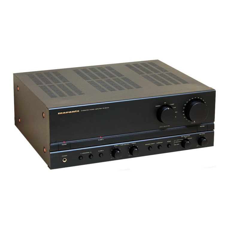
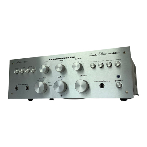
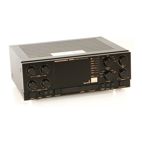
Marantz 1090 User manual

i

Dae
ft
>
Wo?
Be
SO
Ae
TABLE
OF
CONTENTS
SECTION
PAGE
1s
INFRODUCTION)
2:2
hed
eet
4
ae
PERE
ON
GNA
Maia
wee
Siac?
eee
aeRO
ees
Sek
1
22:
PRE-AMPLIBUER:
cc.
<
hse
cies
ca
beter
gy
ee
8
Ook
oi
le
ee
Si
a
iw
hs
Mit
ete
eg
ee
LAG.
ete
ea’s
1
3.7
MAIN
(AMPLIFIER:
c5.ccocceaea
elise
scaateasdeecas
tin
ends
8
Os
reie
OW
6
de
wel
a.
os
9S
aoa
a
Aad
Rhee
See
Ae
a
1
4.
TROUBLESHOOTING
ANALYSIS
.........
0...
ccc
cece
cee
eee
eee
eee
eee
e
eee
e
nena
1
5.
POWER
AMPLIFIER
ADJUSTMENT
.........
0...
.
ccc
ee
teens
eee
e
een
neneaee
1
6.
TEST
EQUIPMENT
REQUIRED
FOR
SERVICING
...........
0...
0c
ccc
cece
ee
eee
eens
2
7.
PERFORMANCE
VERIFICATION
.........
0.0...
cc
ccc
cee
te
ee ee
eee
eee
n
ee
ee
eennaee
2
8.
VOLTAGE.
CONVERSION
36.5
itnd
sek
0.6
wore
nies
Gwate
Ouse
VAww
eA
et
hawt
wee
oe
eee
5
8:1
Voltage
Conversion:
Chart.
-2:ccie:ei
ccc
eect
anda
wa
ee
Madar
wad,
Sees
ad
ese
arare
aitansaha
ek,
Sie
Giver
els
Bea tee
5
9,
MAJOR
COMPONENT
LOCATIONS
........
0...
ccc
cee
cece
eee
eee
ene
eeenanae
6
9.1
Front
Panel
Adjustment
and
Component
Locations
.....
0...
cece
eee
ee
ee
eee
ee
eee
enna
6
9.2
Main
Chassis
Component
Locations
(Top
View)
.......
ccc
cence
eee eee
cece
ec
eeeennnetnvenes
6
9.3
Rear
Panel
Adjustment
and
Component
Locations
.....
0...
0. cc
eee
ee
ee
eee
eee
een
e
anne
7
9.4
Main
Chassis
Component
Locations
(Bottom
View)
........
cc
eee
eee
ee
ee
eee
ee
ee
ee
tence
nnn
7
10.
DIAGRAM
AND
COMPONENT
LOCATIONS
........
0...
ccc
cee
eee
eee
een
ee
8
10.1.
Tone
Component
Assembly
(PFO1)
Schematic
Diagram
and
Component
Locations
.........0.ee
eee
eee
8
10.2
Rear
Panel
Assembly
(PVOO)
Schematic
Diagram
and
Component
Locations
.........0.0ce
eee
ee
eaae
9
10.3
Speaker
Switch
Assembly
(PSO1)
Schematic
Diagram
and
Component
Locations
.......eee
eee
eeeees
10
10.4
Pre-Amp.
Assembly
(P400)
Schematic
Diagram
and
Component
Locations
........
cece
eee
eect
eeaee
11
10.5
Main
Amp.
Assembly
(P700)
Schematic
Diagram
and
Component
Locations
.........0cececeeuecees
13
11.
CONNECTION
DIAGRAM
..........
ee
ee
ee
ene
eee
neta
een
neenans
15
12.
SCHEMATIC
DIAGRAM
«3
occ
eee
eee
cee
er
ee
aa
band
ode
ep
eine
es eu
eee
ee
dees
aes
17
13.
EXPLODED
MECHANICAL
DIAGRAM
...........
0...
ccc
cece
ee
eee
eee
nent
e
eee
e
nes
19
14.
PACKING
MATERIAL EXPLODED
VIEW
............
0...
ccc
ccc
cece
cece
ee
ee
eee
e
enn
ennes
22
15:
BLOCK:
DIAGRAM.
.¢
s:icse¢
o(e08
ett
we
Pe
ie
whe
dian
eae
aoe
daa
gate
Ha
ak
WE
Se
WE
Bea
des
Bares
23
163
PARTS:
LIST)
os
beets
Seed
wieatat
Beste
Aion
suck
we
OF
ale
Recede
damier
binds
Ber
24
17.
TECHNICAL
SPECIFICATIONS

1.
INTRODUCTION
This
service
manual
was
prepared
for
use
by
Authorized
Warranty
Stations
and
contains
service
information
for
the
Marantz
Model
1090
Stereo
Console
Amplifier.
Servicing
information
and
voltage
data
included
in
this
manual
are
intended
for
use
by
knowledgeable
and
expe-
rienced
personnel
only.
All
instructions
shouid
be
read
carefully.
No
attempt
should
be
made
to
proceed
without
a
good
understanding
of
circuitry
operation.
The
parts
list
furnishes
complete
ordering
information.
Most
replacement
parts
should
be
ordered
from
the
Marantz
Company.
However,
a
simple
description
is
included
for
parts
which
can
be
obtained
locally.
2.
PRE-AMPLIFIER
Signals
from
the
input
jacks
(TUNER,
AUX,
TAPE
1
&
TAPE
2)
are
applied
to
the
selector
switch.
Signals
from
the
PHONO
71
and
PHONO
2
jacks
are
applied
to
the
other
section
of
the
selector
switch,
then
to
the
phono-amplifier
and
equalized
for
proper
frequen-
3.
MAIN
AMPLIFIER
The
main
amplifier
consists
of
differential
pre-amplifiers
Q701
and
Q703,
class
‘A’
driver
Q707,
Q709
and
direct-
coupled
drivers
Q717
and
Q719.
Q713
and
O715
act
as
current
limiters.
cy
response.
The
gain
of
the
phono-amplifier
(Q401,
Q403
and
Q405)
is
40dB.
The
outputs
of
the
phono-amplifier
are
fed
to
the
selector
switch.
The
selector
switch
selects
one
of
signals
from
PHONO
1,
PHONO
2,
TUNER,
AUX,
TAPE
1,
TAPE
2
jacks
and
feeds
it
to
the
TAPE
MONITOR
switch
and
TAPE
OUT
jacks.
The
selected
signal
is
then
applied
to
the
MODE
switch,
to
the
balance
and
volume
controls,
and
finally
to
the
pre-amplifier
consisting
of
QEO1,QE03,
QE05
and
QE07.
The
frequency
response
is
controlled
by
the
Bass,
Middle
and
Treble
controls
and
the
resultant
output
is
passed
to
the
PRE
OUT
jacks
through
the
High-cut
filter
net-
works.
These
networks
are
switched
in
and
out
of
the
circuit
by
the
filter
switches.
4.
TROUBLESHOOTING
ANALYSIS
1.
Excessive
line
consumption
a.
Check
for
shorted
0801,
through
0804.
b.
Check
for
shorted
transistor
HOO1,
through
HO04.
c.
Check
for
open
HOO5,
HOO6,
R733,
R734.
2.
No
line
consumption
or
zero
bias
voltage
a.
Check
line
cord,
fuse,
check
for
shorted
H005,
HO06,
R733,
R734.
b.
Check
for
open
rectifiers
Q801,
Q802
or
open
L001.
3.
High
hum
and
noise
level
a.
Check
filter
capacitors
C809,
C810,
C803,
C807.
4.
Parasitic
oscillation
a.
Check
C707, C708,
C709,
C710,
C727,
C728.
5.
POWER
AMPLIFIER
ADJUSTMENT
ADJUSTMENT
OF IDLING
CURRENT
Connect
a
vacuum
voltmeter
to
between
emitters
Q721
and
0723.
Adjust
R771
until
12
mA
is
reached,
Likewise,
adjust
Q724,
Q722
and
R722.

6.
TEST
EQUIPMENT
REQUIRED
FOR
SERVICING
Line
Switch
OFF
Variable-line
switch
Variable
Table
1
lists
the
test
equipment
required
for
servicing
the
Wattmeter
Switch
ON
Mode!i
1090
Stereo
Console
Amplifier.
The
wattmeter,
Variable
Autotransformer
0
V
(fully
CCW)
AC
voltmeter,
and
variable
autotransformer
may
be
assem-
Load
8
ohms
(0.5
mfd
—
OFF)
bled
as
a
test
fixture
as
shown
schematically
in
Figure.
Audio
Generator
1kHz
The
load
resistors
and
AC
ammeter
may
be
assembled
into
Output
5
V
range
a
second
test
fixture
as
shown
in
Figure
2.
Gain
Minimum
AC
VTVM
30
V
range
7.
PERFORMANCE
VERIFICATION
2.
Make
sure
that
connections
between
the
resistive
TEST
PROCEDURE
load
and
the
system
terminals
of
the
Model
1090
have
negligible
resistance
when
compared
with
the
A.
TEST
EQUIPMENT
resistance
of
the
load
itself.
Appreciable
resistance
Refer
to
Table1
for
required
test
equipment.
in
wiring
adds
to
the
total
load,
resulting
in
inaccu-
rate
measurements
of
output
power.
B.
PRELIMINARY
PROCEDURES
xe
3.
Connect
amplifier
output
to
load
and
connect
AC
1.
Make
the
test
setup
shown
in
Figure
1
with
the
cord
to
line
power.
Connect
shorting
plugs
to
the
instrument
controls
set
in
the
following
positions:
Phono
input
jacks
of
the
Model
1090.
Table
1.
Test
Equipment
Required
for
Servicing
Item
Manufacturer
and
Model
No.
l
Use
\
ss
S
=
eee
oer
Distortion
Analyzer
Distortion
measurements
Audio
Oscillator
Sound
Technology
Model
1700B
Sinewave
and
squarewave
signal
source
AC
VTVM
voltage
measurements
(AC}
.
Tektronix
Model
T932
Waveform
analysis
and
trouble
shooting
and
Oscilloscope
i
F
Philips
Model
3232
ASO
alignment
Circuit
Tester
a
ad
—-
:
Trouble
shooting
‘
Fluke
Model
8000
“Digital”
Simpson
M
Voltage
measurements
(DC
Oey
Model
313,
Triplet
Model
801
pe
AC
Wattmeter
lr.
Simpson
Model
1379
_
Monitors
primary
power
to
amplifier
{
pee
es
ppeerllen.
ee
.
4
Moni
ifi
ircui
ReReameter
Conmercial
Graded
S10-A)
OGiEOTs
armel:
ier
output
under
short
circuit
condition
=
ae
1
nee
ate
St
Sete
os
ast
a
Moni
;
:
Line
Voltmeter
Simpson
Model
1359
SPuOlS
Potential
OR
PU
Maly
BOWEr
TO
amplifier
ae
|
shan
|
Superior
Electronic
Co.,
.
.
fat
Variable
Autotransformer
Pee
Model
116B-10A
Adjusts
level
of
primary
power
to
amplifier
l
.
>
Use
phono
plug
with
600
ohm
i
Shorts
amplifier
input
to
eliminate
noise
Shorting
Plug
.
:
across
center
pin
and
shell
pickup
Output
Load
Conaiarsial
Grade
Provides
8-ohm
load
for
amplifier
output
(8
ohms,
+0.5%
100
W)
termination
t
Load
Provides
4-ohm
load
for
amplifier
output
Commercial
Grade
(4
ohms,
0.5%
100
W)
termination
Output
Load
Capacitor
Mytar
Provides
capacitive
load
for
instability
checks
(0.5
mfd)
AC
ve
Goal
Bax
Optional
Item.
Rabricate
in
Monitors
and
controls
primary
power
for
accordance
with
Figure
1
amplifier
upline
Outaue
bakBox
Optional
Item.
Fabricate
in
Provides
various
amplifier
loads
and
can
accordance
with
Figure
2
monitor
shorted
output

105
TO
125VAC
50/60
Hz
l-
LINE
SWITCH
SLO-BLO
VARIAC
VARIABLE
OQ
AC
OUTLETS
AC
WATTMETER
0
TO
150
WATTS
AC
VOLTMETER
0
TO
150VAC
Figure
1.
AC
Power
Control
Box
Simplified
Schematic
,
(MOMENTARY
SWITCH)
O
AC
AMMETER
QO
TO
10
AMPERES
oO
INPUT
OUTPUT
GRD
{GRD
Figure
2.
Amplifier
Output
Load
Box
Simplified
Schematic

TOTAL
HUM
AND
NOISE
TEST
With
shorting
plugs
connected
to
the
Phono
input
jacks
and
an
8
ohm
resistive
load
connected
across
HARMONIC
DISTORTION
TEST
.
Set
the
frequency
of
the
audio
oscillator
and
the
distortion
analyzer
to
20
kHz.
the
speaker
system output
terminals,
connect
a
dis-
2
;
.
Set
the
controls
of
the
analyzer
for
voltage
measure-
tortion
analyzer
across
the
load.
ment
on
the
30
volt
scale.
NOTE:
3.
Adjust
the
audio
oscillator
output
level
until
the
analyzer
meter
indicates
16.8
VAC.
If
the
distortion
analyzer
does
not
contain
a
built-in
volt-
4
meter,
an
AC
VTVM
may
be
substituted.
.
Switch
the
distortion
analyzer
to
Set
Level
and
adjust
SENSITIVITY
for
full
scale
readingon
O~
1%
scale.
Set
the
distortion
analyzer
controls
for
voltage
5
measurements
and
apply
power
to
the
amplifier.
Set
the
volume
contro!
fully
CCW.
Set
the
SELECTOR
switch
to
PHONO.
.
Measure
the
total
harmonic
distortion
with
the
analyzer
and
verify
it
is
less
than
0.1%.
3.
If
the
distortion
analyzer
indicates
more
than
2.0
mV,
NOTE:
refer
to
the
trouble
analysis
section
of
this
manual.
Any
parasitic
oscillation
in
the
amplifier
will
be
displayed
on
the
oscilloscope
when
capacitance
is
switched
into
the
load.
4.
Set
the
volume
control
fully
CW.
If
the
distortion
analyzer
indicates
more
than
20
mV,
refer
to
the
trouble
analysis
section
of
this
manual.
MAXIMUM
POWER
OUTPUT
Connect
the
audio
oscillator
to
the
AUX
input.
Set
.
Switch
the
distortion
analyzer
back
to
SET
LEVEL.
(Do
not
readjust
sensitivity
of
analyzer.)
audio
oscillator
frequency
to
1
kHz.
Set
SELECTOR
7.
Change
the
frequency
of
the
audio
oscillator
and
dis-
switch
to
AUX.
tortion
analyzer
to
1
kHz.
Adjust
audio
oscillator
j
~
Q
With
the
distortion
analyzer
connected
across
the
GURUS
fOr
¢.
ull
<seale
Neading
onthe
O
~cle-scale:
output
load
(8-ohm),
set
the
analyzer
on
the
30
VAC
8.
Measure
the
distortion,
verifying
it'is
no
greater
than
scale.
0.1%.
Turn
the
analyzer
on
and
increase
the
audio
oscillator
9.
Repeat
steps
7
and
8,
changing
frequency
to
20
Hz.
output
to
180
mV.
The
AC
VTVM
should
read
16.8
Distortion
should
be
no
more
than
0.1%,
VAC
:
an
:
i
10.
Check
for
parasitic
oscillation;
there
should
9e
none.

@
EUROPEAN
MODEL
ONLY
8.
VOLTAGE
CONVERSION
This
Model
is
equipped
with
a
universal
power
transform-
er
to
permit
operation
at
110, 120,
220
and
240
V
AC
CAUTION
50/60
Hz.
DISCONNECT
POWER
SUPPLY
CORD FROM
AC
To
convert
the
unit
to
the
required
voltage,
set
the
piug
as
OUTLET BEFORE
CONVERTING
VOLTAGE.
illustrated
so
that
you
can
adjust
the
voltage
as
required.
8.1
Voltage
Conversion
Chart
For
110V
Operation
For
120V
Operation
For
220V
Operation
For
240V
Operation

9.
MAJOR
COMPONENT
LOCATIONS
9.1
Front
Panel
Adjustment
and
Component
Locations
2
i
H
»
by
Mid
LOI
O
wakes
pan
we
Eo.
comule
Hirre
amplifier
“3
4
i
!
a“
°
99
—y—
©
&
G
|
:
{
i
L
i
;
ph.
bi
filter
meine
balance
peakers|
power
ce
ee
=
Ls)
|
|
<=
L076
S403
SE
28
Ssot
Soot
iui
~
~
aa
=
ree
a
|

9.3
Rear
Panel
Adjustment
and
Component
Locations
SPEAKER
SYSTEMS:
CRUTION
#1
\eUED
YECTION
AGAINST
FIRE
HAZ
REPLACE
GALY
WITH
SAME
TYPE
SS
AMP
2500
FUSE
——
3005
INGA
iy
Fo
8
ba
eee
how
4O'8G
|
:
a
a
aeee
Aw
TF
Mine
«
A
”
ad
wou
‘
AAC
ee
hte
\
x
: :
a
ge
wk
dagen
Powegenict
See
we
wae
foe.”
OF
ney
gee
we
_
f
a
thes

10.
DIAGRAM
AND
COMPONENT
LOCATIONS
10.1
Tone
Component
Assembly
(PF01)
Schematic
Diagram
and
Component
Locations
RFO2
22k
100k
RFO4
22k
CFO!
CFOS
0.015
9.015
50V
iv
8
1
T
8
RF20
cFr12
e-{
Fe

9.2
Model
1050
=
707,
Q708
QNOI,QNO2
QN03,QN04,QN23
Q707,
715, O716
'
7
722
Q401,Q402
0403
~
0406
QEO1,QE02
QEO3~
QEO6
QN21,
ON22,QN28
QN24/0N27,
QN30
QNOS
QNI2,QN29
QNI3Z
QNI6,QN3!
QN25,QN26
QyYo!
Q701~
0704
Q705,
9706
Q7il,
Q712
y
pies
:
eae:
“
pia
ais
eee
oe.
pease
20
eer
Moe
2541039
Ror
S$
2S5C2390
Ror
S
2SA1039
RorS
2SC2390
Sore
2SC2390
Rors
2SA1039
RorS
$2473
wo6B
wzo7i
LEO
SLP-132B8
2SA1039
Rors
2SC2390
Ror
S$
2SCI627A
O
or
or
or
——
ee
—
meee
on
—-
———e
———
eee
ee
ee
——
—e
a
ee
Peer
|
uz!
39ov
2SCI627A
Oory
P700
Qurze
R13.
(RTs
Sop
7
tev
a
0802
no)
715
2SC2390
Sore
al
Q72)
ONO5¥
6.0033
Q803
Ps
47/50V
NIB
wZ-o7!
431
200
C705
18p
ae
af
es
Q805
R413
Call
C4i3
R723
WZ-120
Ra05
4
560k
0.0015
ragiy
0-001
or
NFO:
cat
Rais
39mg
(BP?
TT
Q806
~
0809
56
:
R427
220
cHos
niciare
@
RNOS
R721
ores
R729
2.2
S2V-20
Raol
cair
oo
Wy
1
1
>)
9810
med
470
o
Vv
CEO!
R
N2I
CHOI!
0.1
o
WA/cror
1
-
IE
2.2/50
vor!
47/38V
aGkl3,
|
REIS
470
Q
ag
CP
nor
WwO6B
SVvOl-1
401
fa
33k
-37v
a7r3sv
.|Q
=
Fy
Na
62k
riz
QBi2
nue
eh
[|
yt
bere
we:
1
2SA817
ra
0405
fy
703
-o7v
t)
eae
iP
100/10V
CNO3
0.00133
A
ONS
Q813
wile
MET
a
creat
uy
«)
en
$
nnod”
fdower
Tau)
Lares
2502300
100/35v
4
4.3k
RI
4
cals
ON23
SxS
raid
ef
15k
150
aun
R7ai
33
SS
a
330/6.3V
——
:
cral
*
ae
Soo
cae
ory
uiow
——%
=
ar
|
cre
R742
Q714
220p
33
lis
QN24
R7I2
R720;
wav
L5k
150
No
-
R728
ws
@
anos
Bice
gazoe
arog,
po
|
Paa8,,
a
a
ae
2
Rak
:
)
one?
-o7v
{K)
+
Q706
|-3ev
(A
Wy
RNO4
$
RNOB
p
Chia
ae
nnoz
|rHoal
|
jcorrovsrv
()
Qino4
82k
3470
s01!
)
62k
233k
-30v
0710
W
2
c7oz
R706
38v
+¢#—4
+
-e-O—4
QN22
R702
ak
Ge
tk
eS
ie
Rnog
R722b
R726
ONI6
ar/Sev
cHo2
CHO
oS
Ly
12k
eniz
Sone
200
3
027
oC
tae
2
(Q703
a704
R710
27k
oe
Svoi-2
730
R704
07
Bias
ee
e
Raia
Ca4i2
56K
“=
180%
560k
0.0015
*
CT06
ae
18p
RNO2
RNIO
p
Ona
<
J732
B2k
470
jo7v
)
ry
——o-
cine
cNo2
S
ann
SOV
0.0033
ray
“@
Bue
Cote
Pe
Vv
TEPE
IN
+
S
crea
Q7l2
220
PHONO?
TUNER
he
Q722
TEPE
OUT
TAPE
SOURCE
z
ze
PHONG
i
AUX
Sek
Bae
1O0/16V
T
a
|
4
3ev
ch
100/50v
ae.
SELECTOR
TAPE
MONITOR
x
B10
001
ct
i}
2
C4
120k
a
(0a
30v
RN25
220k
R736
QN3!
F804
3012)
aes
R735
330
(2w)
ra
ole
|
elo
2leesl
s/sas
Sys
R608
220
zee
lurig
szat|
furz0
v723| juzea
|
u7e5
J726
‘cama
ee
ay
—=
PoP
a)
fo
99
0
0
—
—*
—
GO
C
<a
()
woo:
[|i
s
le
b
b]
[od
=]
eae
os
4 &
]
6
)
|
YO!
=
4
2
Lj
8
Js04
JSO5
<a
—
ee
aT
OO
>
O
©
s001
PHONES
i
yoo2
80
i}
7”
Hg
2
a
P
ae
1
bie
rene
evs
3
3
2
g
_
SYSTEM
ree!
(01
0.22
|cFoz
0.22]
98
81s
+8
eS
hemes
:
ra
T
Ss
Tet
2
oFF
142
poo.
&
BALANCE
3608
e713}.
[8
|
mh
Pe
as
2)
1829
|
SPEAKERS
SPKI
SPK
2
YK
\
dH
'o
&
MONO
Sc
ey
SPEAKERS
$003-1
$003-2
o
O
S
Low
‘MONO
ROOI-2
3ASS
BASS
iS
FILTER
look
4
nd
coo!
FO3
£9.
Foo!
0.022
W022
so
tFOT7
tz
[=
oe:
ee
LL
ts
=
aa
2
—|--
4
cooz
ee
0.022

10.
DIAGRAM
AND
COMPONENT
LOCATIONS
10.1
Main
Assembly
(P700)
Schematic
Diagram
and
Component
Locations
10.2
LED
Lamp
Assembly
(PY00)
Schematic
Diagram
and
Component
Locations
=a
[PY
YH2274
2220
10
-—
P700
PHONO
I
PHONO
2
yoos:
O
TUNER
|
AUX
Olv0s.
i
TEPE
IN
TEPE
OUT
10.3
Loudness
Assembly
(PS00)
Schematic
Diagram
and
Cpmponent
Locations
wor
fk
R
|
|
=
bed
Oto
a
3.3k
R7I3
R715
3.3
R413
Cait
560k
0.0015
300
270
R418
15k
R408
R42
R424
C46
Hr
330/6.3V
Té404|
caos
irr,
82
|100/
Ki)
o406
RHO2
|RHO4
33k
$
100/10V
RHOS:
RHO7
3
110%
39k
|
15k
a
72!
c707
47/50V
C705
18p
CHO3
0.
R7OI
470
Bos,
R721
1
CHO!
0.1
HOF
RNO?
RHO}
SS
IRNOS
Bk
aaa
33
+
220p
R741
33
acr
EERE
Tol
—)
ONS
&
R727
10
Bs
Q708
++
R702
470
c7o2
R706
IRNOG
$
RNOB
150p
Ik
Q703
Q704
R710
33k
RE22
2k
O—
Wy
4730
R704
N12
CNO4
Fc0ss
OF
QiINO4
6.8%
R734
benoe
Lek
Q
R726
ONi6
S027
Calg
5
0.001
414
C4l2
R4223
R436
560k
0.0015
3-9k
F100
TAPE
MONITOR
a
———<—=
——aee
—e
ed
———
——
N
fo}
7)
rs)
CJ
e
e
°
e
e
°
e
e
@ite
cso3
z{
i
1
RBO3
2.4K
QNiO
L702
R724
ye
2
0.27
]
+
JON
14
(=
+
Q716
u701
On7oz
Quros
717
718
00
0
O—_«x»
—
mma
JSO4
|
ied
VOLUME
—————I
4.6720
100750v
CBIO
0.01
J807
F804
J808
R806
220
ewmeseee
()
omm
10.4
Volume
Assembly
(PS50)
Schematic
Diagram
and
Component
Locations
J722
|J7I9
y72)
ussa
(@)
usss
@
ysss
@
RS51
ss3
(@)
Js52
@
Js51
@
R736
330(2W)
R735
330
(2w)
J723
J724
|
J725
ae)

PVOO
REAR
PANEL
ASSY
|
10.2
Rear
Panel
Assembly
(PVO0)
Schematic
Diagram
10.3
Speaker
Switch
Assembly
(PS00)
Schematic
Diagram
and
Component,
Locations
and
Component
Locations
—Eavo2z
B
°
RVIZ
JVI2Z
JV11
JV1O
JVO7
JV08
JVO9
JHO2
JNO
ear
|
cCeccsooO
Pe
ecccccece
é
avo3
JVO5
Jvo2
Coe
SYSTEM2
S12
MAIN
IN
PREOUT
10

10.4
Pre-Amp.
Assembly
(P400)
Schematic
Diagram
and
Component
Locations
P400
PRE
AMP
|
@
fw
[ofa
fo lo
fro
]-
OVQDdOQO00O0
5
JNO!
JNOZ
0
[m[~
Jor fer
fa
fur
fro]
—
OO000
Ad,
+
C423
w@
47/35V
JHOI
Q801,0802
JBI2
DSI3Z3B200V
1.8A
0806
OC
ee
ee
ee
|
ee
()
<5
QF
3
F802
J806
J80T
J808
JBO9
J810
Stl
Q40!
~
406:
——
Q409:
MV-I3
Q410
:
WZ-240
c409
100/10V
i
Srrov
car
+
RHO!
18k
teuaz?
ROS.
Wk
REI5
100k
REIS
I2k
Q803
:
2SC!1407
+
RE2O
12k
t—it-—_4
0804:
286945
ceo!
Q805
,Q806:
wz!120
0.01/500V
cae
6800/50V
mo
air
WBS
sia
||
=
ii
|
bey
REO2
2
2k
oQgg0g000
QE01,02,05,06
:
28c1222
QE03,
04,
07,08
:
2SA750
OOO0000
®
JNO1
®
JNO2
J402
403
J406
804
(0)
5803
J817
F802
J816
J805
©
sas
—b<-
2
J820
AU
Al]
SL
sr
©
zlz1=%*
Bo
B02
2
°
=
tO)
8
3
site)
R404
+
as)
R402
408
@
e{fe
©
©
e—W\—
F408
R414
one
f,,
e
Loui
e
e
can
tes
+
pas
cat2
oud
o—Wi—
©
&-1
Fe
—W—e
ae
<a
Pe
C413.
C415
8
a|
cae.
Nana
ibe eho
e
ese
eo
seeite
ejre
R427
3
5
R428
R431
z
R432
.
®
|
o
i
7
nt
RE31
8
ey
RI
vVVVV
=
ao
RE27
has
5S
yer
2 R
+
5°
“naon:
$
—Wi—*
ew
(s)
eee)
g
we
{
)
Pry
ch
2
~
ess
ee
*s
"Seo
@e
= FAK
!
3
9
3
&
|
;
1CE19
ith
oa
mee
”
+
9)
Cts
°
f
”
o—W\—e
=
+
4
3
9
ett
'e
e.
(
23
y
aes
#
3 a
+
RE24
5°
le
9
2
<
3A
&
5
oe
=
LJ
H
&
4
©
©
8
©
CEOs
\
2
5813©
pte
Tea
eee
ed
E04:a
a
SD
eel
G2
@:
JEO2
\
-
sui
CEIB
—~
+
'
CE16
‘@)
i
“
@®
©
2©
CEOS
e#—!—-e
_CE06
ed
Fas
8
3
2
.
ew
t
=~
we@QE04
=
”
e
a
q
:
Be
.
nos.
Seyi}
@fyendodede
er
°
ro)
+
'
+
w
oS
ea
!
Qe
Ch
cm
oo.
o—_____»
,
uN
e
oO
e
eo
ea.
ot
©
ig
§
j
_
°
REO3
a
©
co)
18
03
Ws
OT
>
2
Seo
Ta
gS
TS
ar
s4
ae
7
+
2
2
+
n
ee
4 ‘
Fs
. *
vi
Fe
e
(c)
hed
OR)
=
C4)
Hy
ae
J
E01
g
°
e
0:
e-!
e
e
of
ceot
@E
&
G
CEO2
¢
w
°
>
°o
CE17
s
g

10.5
Main
Amp.
Assembly
(P700)
Schematic
Diagram
and
Component
Locations
P700
ey
es
ee
ee
eee
MAIN
AMP
ASSY
0.47
2W
L701
2.2
pH
¢70!
22/50v
oO
‘
O
<|
|"
OF
2
47
i
bd
R703,
ro
Sik
1703
&
R731
Sik
iO}
3
pl
C733
100/16
C740
20p
mI
C741
20p
©
bad
R702
470k
—_
—
—
oo
R766
0.47
2wW
L702
2.2pH
RT74
100
100/35V
Q7l4
cTIi6
Q728
S
oO
Nn
13
C737
ee
24h
R7IS
+
op
sbeo
—-
Sod
—ww—*
vely
9220
2229
3
o
‘>
oil
toe
he
Ind

11.
CONNECTION
DIAGRAM
PVOO_
REAR
PANEL
ASSY
wos}
[inos
|
aes
PFOI
PHONO
|
O—O
PHONO
2
ats
TONE
O90
CONTROL
JVI
3
ASSY
P400
PRE
AMP
ASSY
2m
C748
0.004
50V
~
PSOO
ovsos
SPEAKER
SWITCH
QO
JSII
(n)
TYPE
—_
———
———e
——
ee
a

12.
SCHEMATIC
DIAGRAM
TUNER
AUX
SOURCE
PHONO!
TAPE
|
1
2
PHONO
2
ne
TAPE
2
SELECTOR
TAPE
MONITOR
s40t
$402
IN
vo
|
LOUDNESS
TONE
MODE
$403
PVOO
REAR
PANEL
ASSY
|
P400
PRE
AMP
Q401
~
406
:
2S5Ci222
Q407~408
cary
|
3
a
O.8V,
()
»
($2472
o
2
is
8
R432
270k
Q409:
MV~i3.
[-————o,
©
Cy
(:)
Q410
:
WZ-240
O©V@
5
od
eh
TAPE
|
Oo
RE38
560
sourceo
(2)
® @
TaPe2©
|
]
soz
$403-2
CHO!
6.015750V
Re
Toor
040
6
EAA
PHONO
!
18.5V]"
94
cazo
braze
P31
Sp/SOV
S3.3k
1/4W
1
2
PHONO
2
2
eae
SA
saa
oes
ee
eas
O
R433
Or
I
Pe]
100
30
1
o-50
1
t
6-26
i
66
1
pal
TUNER
ar)
O
O
AUX
IN
TAPE
OUT
Q801,0802
1812
OSi33B200V
1.8A
[Reol
38.2v,
100
I72w
IN
TAPE
2
OUT
MAIN
IN
PRE
OUT
tec
ceo!
0.01/500V
eis
JBI4
«
8
io
«{
ale
3|8
slg
s\8
4
—
®
Q803
:
2SC1407
Q804
:
28C945
Q805
,Q806:
wz!120
Caos
calo
6800/50V
6800/50V
I-4av
3810
+4
REO?
2
2k
JNOS.
QE01,02,05,06
:
28ci222
Qvol
QV03
~QV04
Qvo2
001
2SK30Y
280945
2SC1327
S5VB-20
200V
6A
QV05,QV06
QvO07
WwO6B
WZ040
"]
a
—|—
||
42v
9990
9O=G9090
000000
0
J
t+
©
L
=
REIS 100K
REIS
12k
QE03,04,
07,08
:
25A750
il
[ft
5
1°
8
fo)
z
'
3
10.
ll
a
INOS}
77
mts
200p/50Vv
PFOI
TONE
CONTROL
ASSY
s
=
C744
0.0015/50V.
C701
2.2/50V
+
Arg
avon
|
R701
a7O%
|
C719
0.1/50V
MAIN
AMP
A
ic
R757
100
'V
Oy
of
0739
em
100/35
0734%
R763
0.47
2w
L701
2.2yH
S
702
Om
OO
L702
2.2pH
R774
im
Pevereres
Wt
Ape
eo
(00
6]
—
[050
J
—
Q70I~
704
2Sa7!
7.
ras
oros~ros
Beciese
ares,
Saale
Q709,710
2scis40
Q74a
Q711,712
25C828
0739~0742
Q713,714
280945
wo6B
Q715,716
254733
Q717,
718
2S5D415
Q719,720
258549
Q721,72e
250588
Q725~738
1S2472
0723,724
256618
oer
0
sa)
O
|
PHONES
ISO?
°
Jo10
17
oO
O
i
O
iE
He
PSOO
L
—_
18
SYSTEMI
SYSTEM
2

13.
EXPLODED
MECHANICAL
DIAGRAM
LOOt
o>
sor
@
QO08
ef
A
OLOF
PSO
O62F
0058
GOOI(N)
GOO!
(U,C)
19
20

13.1
Rear
Panel
for
U.S.A.
&
Canadian
Model
:
YS
"
A
—
2
|
SS.
AQ)
ATS
=
_
:
Q,
oe
Ss
a
13.2
Rear
Panel
for
European
Model
21

14.
PACKING
MATERIAL EXPLODED
VIEW
22
@
(U)
for
U.S.A.
e@
(C)
for
Canada
e
(N)
fo,
Europe
Other manuals for 1090
1
Table of contents
Other Marantz Amplifier manuals

Marantz
Marantz PM5004 User manual

Marantz
Marantz SC-7S1 User manual

Marantz
Marantz 40n User manual

Marantz
Marantz CD-400 User manual

Marantz
Marantz PM6004 User manual

Marantz
Marantz MM8077 User guide

Marantz
Marantz AV7005 User manual

Marantz
Marantz 1200 User manual

Marantz
Marantz PM-KI-PEARL User manual

Marantz
Marantz 1070 User manual

Marantz
Marantz MA-9S2 User manual

Marantz
Marantz PM7001KI User manual

Marantz
Marantz PM4200 User manual

Marantz
Marantz 4100 User manual

Marantz
Marantz PM7000 User manual

Marantz
Marantz PM-11S2 User manual

Marantz
Marantz PM8200 User manual

Marantz
Marantz PM8005 User manual

Marantz
Marantz THX Ultra MA-6100 User manual

Marantz
Marantz SM6100SA User manual