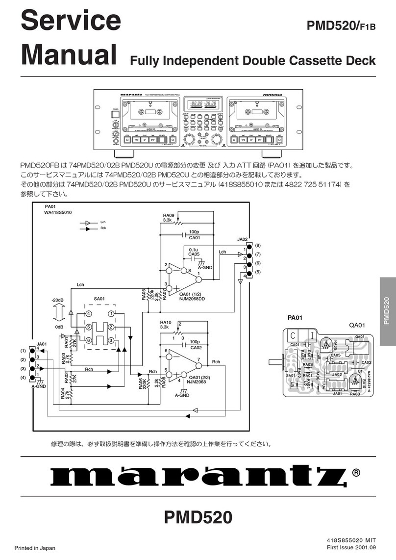
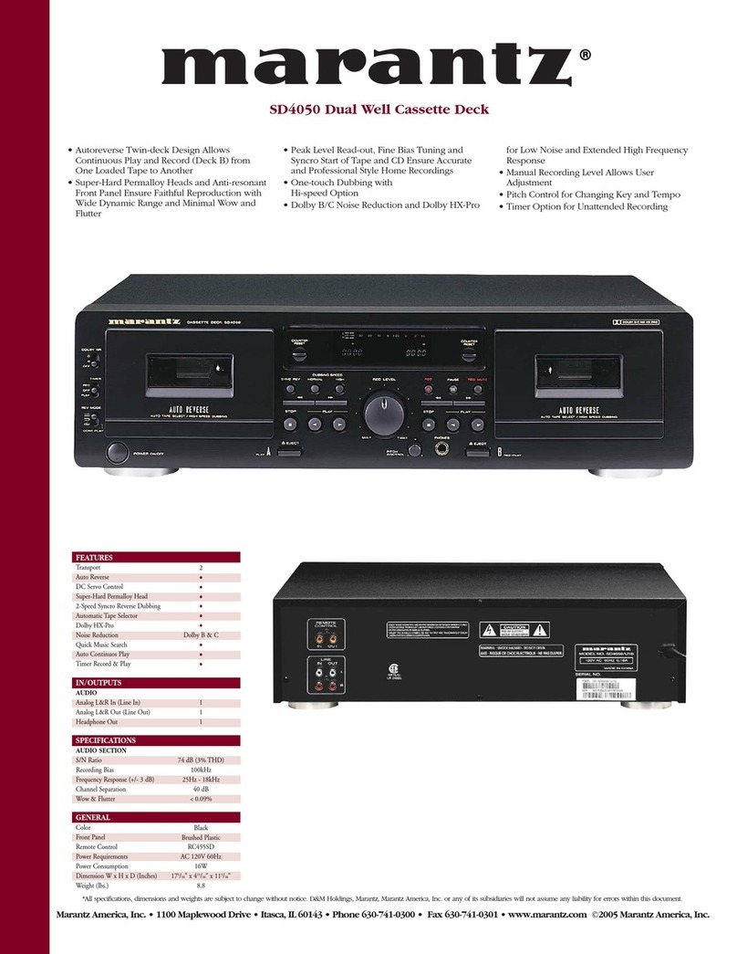
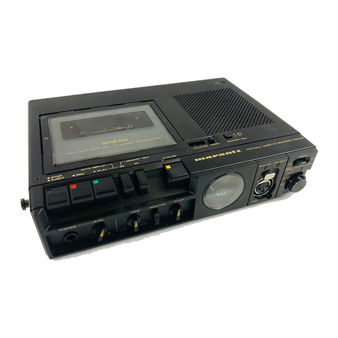
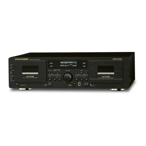
Marantz 5010 User manual

NBS
=a
AVS

TABLE
OF
CONTENTS
Section
Title
Page
1.
PW.
BOARDS
...........00
0005
efike
heed
ss
a
Wai
tavisthan
Pa
dide
a
Mecaueiost
Pi
eiade
ds
Gu
ee
rteewaut
bbe
Mints
cae:
GH
a
i
2.
TEST
EQUIPMENT
REQUIRED
FOR
SERVICING
..
0.0...
ec
ee
eee
eee
tt
eee
tents
1
Sy
DISASSEMBLY
c5:
55%,
nse
ase
8
tein
ae
nce
Selena
we
he
WE
ae
elec
o
ad
Wieices
pite
eee
ake
ye
be
Dee
scents
Te
2
3.1
Removing
the
Cassette
Case
Escutcheon
...........020022eeeecee
*E
fenb
2oNsi
Hades
tat
wh
aD
Masab
cohen
ane.
estate
ete
Bae
2
3.2
Removing
the
MainP.W.
Board...
1...
1.
ee
eee
eee
eee
eee
eee
eee
2
3.3
Removing
the
Mechanical
Chassis
......
TF
BeG
WO
ead
th
ROW
Ia
Se
OSE
Te
ANS
es
one
NR
Neon
Me
"hc:
cebdat
dal
'd
Ceutws
Soto:
bp
BGA.
Na.
FOr
aloe
2
4.
ADJUSTMENT
PROCEDURES
..
0...
cc
en
re
tee
ee
eee
ee
tee
ee
eee
tee
eee
eee
tes
3
4.1
Mechanical
Adjustments..............
oor
waka
Sa
a
Gad
heme:
soe
Sig
hat
scacd
feta.
cehel
Shiba
anerodies
iSndacst
Hiahe:
Biedeatecst
ae
8
3
4.2
Electrical
Adjustments
and
Measurements
.........0..
020
cece
er
euueeee
5
Aeitas
le
terete
al
aye
fed
Siacee
ets
ican
eicale,
8
5.
VOLTAGE
CONVERSION
FOR
EUROPEAN
MODEL
.....
1...
ce
et
ee
eee
ee
eet
eee
21
Bi
DIAGRAMS
~
5
53532
co
hs
he
a
es
ak ee
ER
ae
ee
Se
5
OS
ek
at
aoe
dak
Se
2
22
G21)
‘Level
Diagrain
2.62525
3-45
Sos
wt
Ron
ied
ew
he
a
oe
Ge
ee
en
ee
See
ate
enti
Daan
22
G2:
Block
Diagranns
55-55:
ccecece
ce
ete
Sic,
eae
casa
rie
Paes
eheie
ble
ede
OE
TOG
nS.
erate
ps
Dia
ee
Ear
whey
ee
R
NE
DiS
ah
Wee
23
6.3
Connection:
Diegrain
esse
icdcersc
i
Scan.
Be
eee
Rcsni
cae
lec
82
wha
Senso
ae
AW
iain
be
le
WN
RS
BS
eT
ee
eee
ls
HS
SOG
25
6.4
Schematic
Diagram
.
BPG
ae
eR.
eee
We
Raley
eae
Aig
de
ee
bug
d
Span
see
pete
une
or
dca
taapetdnra
te
Sage
caieaes
aamhergnre:
ane
27
6.5
Pre-Amp,
Power
Supply,
Dolby
Board
Schematic
Diagram
and
Component
Locations-P100
2.1...
.
et
eee
29
6.6
LED
Board
Schematic
Diagram
and
Component
Locations-P600.............20-5
Migeteene
a8
Bleck
09,
be
aes
we
8
...33
6.7.
Terminals
Board
Schematic
Diagram
and
Component
Locations-P700.............
00.
ee
eee
eee
eee
ee
tee
eee
33
6.8
Fuse
Board
Schematic
Diagram
and
Component
Locations
-P400-EUROPE
............
0.2.
ee
ce
ee
eee
eee
34
7.
MAJOR
COMPONENT
LOCATIONS...
1...
cc
ee
eee
eee
eee
tee
eee
ee
eee
35
7A
Cabinet:
Front
View:
vised
Sue
ee
aes
Sate
ee
ce
ar
ee
ae
Bae
OE
AG
eas
be
8
SG
ga
ete
Race
ae
a
ee
35
7:2.
Chassis:
-
Toph
ViGw
soi.
4eicse
oder
a
hesece
Bg
as
8
8
BREE
%,
BEIT
euieen
BUSA
aaa
elke
AG
ara
bales
@
Kaaba
35
8.
EXPLODED
VIEWS
AND
PARTS
LIST.....
otk
SRGNG
A
Be
we
ewes
a
tr
SAV
ws
PLR
ase
ier
eaten
Hare!
wits
tote
wie
a
aca
aia
bed
36
8.1
Top
Cover
and
Main
Chassis
..
0.0.0...
cece
te
ete
re
ete
ee
tee
nane
a
See
ee
hanes
a
ecard
MOA
36
8:2:-
Front:
Pariel.
aid
Chassis.
.o
cyea2
cco
aie
Siow
ile
a
scutes
ance
Le
"arate
whee
noel
ws
eirascal
ia
hehne
desde)
as
leleelibcevenievene
dule-lede
ere
Bowie!
acetara’
oat
37
8.3
Associated
Mechanism
for
Cassette
Tape
Operation...
..
0.0...
cee
ee
ee
ee
eee
ee
eee
teeta
wens
38
8.4
Buttons
for
Tape
Operation.
...........-.
GL
Anse
Sa
GP
bres
62500:
ebte
tocar
tebe
tela
sare
leelac
is
eiceleieue
ties
bok
cen
aean
St
aPanee
te
39
B25.
Head
:CNassts
2.
se
oes.
Sc.
5
bP
Stee
he
Sloe
Gas
SO
ie
Sete
ed
A
bee
Gels
oa
EE
et
do,
datas
39
8.6
Parts
Assembled
on
the
Top
of
the
Chassis...
0.0...
ee
eee
ee
ee
ee
eee
te
eee
eee
40
Bed
Bly
wheels
coos
ie
eesies
sti
eae
eee
ee
ira
ose.
oon
yenize
ang
Ae
Skah
eh
Wee
saree
ae.
Selo
Deane
dente
elte
cada
ele
teer
etveassle
ake
41
8.8
Switch
Location
for
the
Tape
Operation
.......
Bela
brid
Torte
a
I
wineries
Sot
Nice
oat
1S
estar
cesar
ib.
sah
ariw-0
Weide
Dicee
ipsa
yee
ce
lacdncayte
41
8.9
Parts
Assembled
on
the
Reverse
of
the
Chassis
..
1...
0...
.
cc
eee
eee
ee
ee
eee eee
ee
eee
teeta
nes
42
8.10
RearPanel..........
Sits
ates
Soa
le
(ot
oie
aate!
SNR
GUE
eae
eal
WE
Sek
Wes
eke
fo
trinihs
GUGM
AGEG
9
ta
By
iaebe
al
eset
...44
8.11
P.W.
Boards
and
General
Parts
Pebecaeee
au.
oe
ake,
al
caebewh
arta
ace
e,
e
Biecd
Sea
baat
Neva
gs
frat
Meaney
aise
ae
ab
peal
aeaey
Cilarto
beara
lean
euce
aie
wee
45
$12:
Packing
Materials:
i.e:
3
8:
isa
gig
cee
acorn
ie
eae
alse
a
ORE
ow
nc
Hoes
Dold
GP
ALT
eS
©
Go
earlbe
Sean,
lke
aw
“olcar
sd
Tah
LT
Sv
bee
aise
See
50
9.
GENERAL
SPECIFICATIONS
©...
0.0...
.
eee
ee
ee
ee
eee
ee
eet
eee
ere
eee
ee
een
51

INTRODUCTION
This
service
manual
and
prepared
for
use
by
Authorized
Warranty
Station
and
contains
ser-
vice
information
for
Marantz
Model
5010
Stereo
Cassette
Deck.
Servicing
information
and
voltage
data
included
in
this
manual
are
intended
for
use
by
the
knowl-
edgeable
and
experienced
technician
only,
All
instructions
should
be
read
carefully.
No
attempt
should
be
made
to
proceed
without
a
good
understanding
of
the
operation
of
the
Cassette
Deck.
The
parts
list
furnishes
information
by
which
replacement
parts
may
be
ordered
from
the
Marantz
Company.
A
simple
description
is
in-
cluded
for
parts
which
can
be
usually
obtained
through
tocal
suppliers.
1.
P.W.
BOARDS
As
can
be
seen
from
the
circuit
diagram,
the
chassis
of
Model
5010
consists
of
the
following
units.
Each
unit
mounted
on
a
printed
circuit
board
is
described
within
the
square
enclosed
by
a
bold
dotted
line
on
the
circuit
diagram.
1.
Pre-Amp,
Power
Supply
&Dolby
....
mounted
on
P.W.
Board,
P100
2.
LED
a5
cei
2
3
mounted
on
P.W,
Board,
P600
3.
Terminals
.
..
mounted
on
P.W.
Board,
P700
4.
Fuse
(N&P
versions
only)
......
mounted
on
P.W.
Board,
P400
2.
TEST
EQUIPMENT
REQUIRED
FOR
SERVICING
For
measuring
or
checking
the
Model
5010,
the
following
instruments
and
materials
are
necessary.
VTVM
Audio
Oscillator
(af
OSC)
Attenuator
(600
Q)
Oscilloscope
Bandpass
Filter (1
kHz,
500
Hz)
IEC
A-Curve
Filter
Wow
and
Flutter
Meter
Torque
Meter
(Cassette
Type}
Digital
Frequency
Counter
Distortion
Meter
Blank
Tapes
(Completely
erased
with
bulk
eraser)
TDK
AC-211
(Normal)
TDK
AC-511
(CrO,)
SONY
CS-30
(Fe-Cr)
NOTE:
if
any
doubt
is
noted
in
a
measured
value,
use
new
tape.
@
Test
Tapes
(New
Tape)
MTT-111
Wow
and
Flutter
Tape
Speed
MTT-112
Measurement
of
Output
Level
Signal-to-Noise
Ratio
MTT-150
Adjustment
of
Output
Level
MTT-116U
Frequency
Response
(for
Normal)
MTT-116K
Frequency
Response
(for
CrO,,
Fe-Cr)
MTT-121
Cross
Talk
MTT-141
Channel
Separation
BIAS
and
EQ
switches
setting
in
accordance
with
tape
used
are
as
follows:
Switch
Position
BIAS
Switch
|
EQ
Switch
;
i
a
a5
a

RRB
am
Pease
ERE
Zz.
3.
DISASSEMBLY
3.1
REMOVING
THE
CASSETTE
CASE
ESCUTCHEON
Push
the
cassette
case
escutcheon
at
the
two
positions
upward
in
the
arrow
A
direction.
As
it
will
be
detached,
take
it
out
in
the
arrow
B
direc-
tion.
3.2
REMOVING
THE
MAIN
PW.
BOARD
Remove
the
seven
screws
A,
B,
C,D,
E,
F
andG
holding
the
Main
P.W.
board.
Unplug
the
con-
nector
H.
Then,
draw
it
out
with
taking
care
of
not
applying
excessive
force
to
any
lead
wire.
3.3
REMOVING
THE
MECHANICAL
CHASSIS
-
Remove
the
five
screws
A,
B,
C,
D,
and
E
holding
the
mechanical
chassis.
Remove
the
record
lever
spring
assembly
F,
Then,
draw
the
chassis
out
with
taking
care
of
the
tape
counter
and
operat-
ing
levers,

4.
ADJUSTMENT
PROCEDURES
4.1
MECHANICAL
ADJUSTMENTS
4.1.1
Adjusting
the
Flywheel
Thrust
Adjust
the
thrust
screw
at
the
flywheel
bracket
until
the
clearance
between
the
capstan
tail
end
and
thrust
bearing
is
0.1
to
0.3mm
as
shown,
using
a
phillips
screw
driver.
For
adjusting,
feel
of
axial
dropping
of
the
flywheel
for
proper
clearance
as
this
cannot
been
seen
through,
Then
paint
the
screw
to
lock.
4.1.2
Adjusting
Pause
Timing
Set
the
unit
in
the
play
mode
of
operation.
Then,
adjust
the
bend
angle
of
the
pinch
roller
bracket
arm
(point
A
in
the
line
drawing)
until
the
clear-
ance
between
the
pinch
roller
and
capstan
is
0.1
to
0.3
mm
at
the
time
when
the
take-up
reel
is
stopped
by
slowly
pressing
the
PAUSE
push-
button
down,
NOTE:
To
widen
the
clearance,
make
the
bend
angle
smaller
(in
the
direction
C).
To
make
the
clearance
narrower,
widen
the
bend
angle
(in
the
direction
B).
4.1.3
Adjusting
the
Pinch
Roller
Pressure
Measure
the
pressure
of
the
pinch
roller
using
a
gauge
as
shown.
For
measurement,
draw
the
pinch
roller
in
the
arrow
direction
in
which
it
is
detached
from
the
capstan
shaft
and
gradually
return
it
toward
the
capstan.
Read
the
gauge
at
the
time
when
the
pinch
roller
starts
turning.
The
standard
pressure
is
300+50g.
!f
the
pressure
is
out
of
the
range,
bend
the
pinch
roller
spring
around
the
point
A
in
the
direction
B
or
C.
NOTE:
To
make
the
pressure
strong,
bend
in
the
direction
B.
To
make
the
pressure
weak,
bend
in
the
direction
C.

4.1.4
Adjusting
the
Play
Timing
It
is
normal
that
when
the
PLAY
pushbutton
is
depressed,
the
take-up
reel
table
turns
first,
then
the
pinch
roller
is
rotated.
The
reel
table
and
pinch
roller
must
not
start
turning
at
the
same
time,
NOTE:
Make
certain
that
such
a
subsequent
operation
is
made
irrespective
of
locking
state
is
depressed
slowly
without
load-
ing
the
tape.
(1)
Checking
for
adjustment
Check
whether
or
not
the
clearance
between
the
pinch
roller
and
capstan
is
0.2
to
0.5
mm
when
the
take-up
reel
table
starts
turning
with
the
PLAY
pushbutton
depressed
slowly.
(2)
Adjustment
Bend
the
pinch
roijler
bracket
at
the
point
that
touches
the
head
chassis
stopper.
In
the
line
drawing,
bending
left
reduces
the
clearance
be-
tween
the
capstan
and
pinch
roller.
NOTE:
Make
certain
that
the
pinch
roller
bracket
does
not
leave
touching
the
head
chassis
stopper
in
the
play
mode
of
operation
as
a
result
of
excessive
bending.
0.2~0.5mm
CAPSTAN
SHAFT
PINCH
ROLLER
Seis
CHASSIS
STOPPER
4.1.5
Adjusting
the
Play
Torque
Put
the
two
pawls
of
the
circular
plate
spring
on
proper
stepped
position
of
the
reel
rest.
The
adjustable
torque
range
is
40
to
70
g-cm.
To
make
the
torque
high,
put
the
pawls
on
a
shallow
step.
For
lower
torque,
put
them
on
a
deeper
step.
@
Checking
the
take-up
clutch
for
sliding
Make
certain
that
the
flywheel
rotates
freely
when
the
reel
table
is
locked.
The
flywhee!
that
revolves
irregularly
or
stops
is
not accept-
able.
4.1.6
Adjusting
the
Fast
Forward
and
Rewind
Torque
The
fast
forward
and
rewind
idler
has
a
torque
adjust
plate
spring
(part
A
in
the
line
drawing),
which
has
two
pawls
(part
B)
at
its
ends.
Set
the
pawls
in
proper
one
of
the
three
steps.
To
make
the
torque
high,
set
the
pawls
in
the
shallowest
step.
For
lower
torque,
set
in
the
deepest
step.
INCREASE
DECREASE
OEE
Yi,
INCREASE
DECREASE
i
P22

4.1.7
Positioning
the
Motor
Pulley
Loosen
the
set
screw
and
adjust
the
motor
pulley
position
until
the
clearance
between
the
pulley
and
motor
is
4.8mm
as
shown.
Tighten
the
set
screw,
4.1.8
Adjusting
the
Tape
Speed
Adjust
the
semi-fixed
resistor
inside
the
motor
until
the
tape
speed
is
2985+5Hz,
using
a
screw
driver.
4.1.9
Adjusting
the
Rewind
Idler
Side
Pressure
Make
certain
that
in
the
rewind
mode
of
opera-
tion,
the
rewind
idler
does
not
slip
on
the
supply
reel
table
when
this
is
held
by
hand.
If it
slips,
change
the
hanging
position
of
the
rewind
idler
arm
return
spring
on
the
chassis
in
the
arrow
direction
step
by
step
until
it
does
not
slip.
MOTOR
PULLEY
ADJUSTING
SCREW
SPEED
DOWN
at
)
SPEED
UP
ARM
RETURN
SPRING

&
S002
MOTOR
SWITCH
BRACKET
$003
<
PAUSE
MUTING
\
[
SWITCH
4
$009
PLAY
TIMING
SWITCH
$004
:
PLAY
MINE
SWITCH
S
Da
a
$005
REC.
MUTING
SWITCH
4.1.10
Positioning
the
Switches
(1)
Motor
switch
Turn
the
motor
switch
in
the
arrow
direction
until
it is
screwed
tightly.
Make
certain
that
the
contact
gap
is
wider
than
0.5
mm.
MOTOR
SW
(2)
Record
muting
switch
In
the
stop
state,
loosen
the
screw
holding
the
record
muting
switch
and
position
this
so
that
the
clearance
between
its
end
mold
tip
and
mounting
bracket
may
be
6mm,
Tighten
the
screw,
Make
certain
that
when
the
record
lever
is
pressed
in,
the
record
muting
switch
contact
A
is
made
close
and
the
contact
B
is
broken
out
securely,
FLYWHEEL
ADJUSTING
SCREW
REC
MUTING
SW
(3)
Pause
muting
switch
In
the
stop
state,
loosen
the
screw
‘holding
the
pause
muting
switch
and
position
this
so
that
the
clearance
between
its
end
tip
and
pause
arm
may
be
1
to
1.5mm.
FLYWHEEL
\
PAUSE
LEVER
(4)
Start
muting
switch
In
the
stop
state,
loosen
the
screw
holding
the
start
muting
switch
and
position
this
so
that
its
contact
clearance
may
be
0.5
to
0.8mm
with
leaving
the
contact
tip
in
contact
with
the
head
plate,
Tighten
the
screw.
HEAD
PLATE
ADJUSTING
SCREW
Pn
“TO
CONTACT
0.5~0.8mm
(5)
Play
muting
switch
In
the
stop
state,
loosen
the
screw
holding
the
play
muting
switch
and
position
this
so
that
the
clearance
between
its
end
tip
and
play
lever
may
be
4mm,
FLYWHEEL
7”
PLAY
MUTING
SW
oe
“ADJUSTING
SCREW

4.1.11
Setting
the
Eject
Spring
Hang
the
eject
spring
at
proper
one
of
the
three
holes
so
that
the
cassette
lid
can
be
opened
well.
After
setting,
bond
the
spring
to
lock.
EJECT
SPRING
ADJUSTER
——
--
|
INCREASE
ROLLER
>>
ADJUSTING
SCREW
4.1.12
Adjusting
the
Interlocking
Mechanism
IMPORTANT:
In
aligning
the
mechanical
assem-
bly,
place
it
alone.
1.
Lay
the
mechanical
assembly
by
its
side
as
shown
in
Figure
1.
2.
Loosen
the
screw
E
holding
the
adjuster
C
a
little
until
this
moves
freely.
3.
Adjust
the
interlock
cam
B
by
finger
until
the
clearance
between
the
interlock
cam
B
and
the
lock
cam
release
arm
A
is
0.1
to
0.6
mm.
.
Keeping
this
clearance,
tighten
the
screw
E
to
fix
the
adjuster
C,
which
will
be
in
light
con-
tact
with
the
cassette
guide
shaft
D.
.
After
completion
of
Steps
1
through
4,
per-
form
checking
by
proceeding
as
follows.
a.
Open
the
cassette
door
by
pressing
the
STOP/EJECT
pushbutton.
b.
Close
the
cassette
door
slowly
by
hand.
Make
certain
that
the
PLAY
pushbutton
will
not
move
in
the
range
of
the
position
A
to
B
in
Figure
2
while
the
cassette
door
is
closed.
NOTE:
The
cassette
door
is
locked
at
the
position
C.
CAUTION
If
the
PLAY
pushbutton
is
locked
in
that
range,
replace
the
following
parts
as
these
may
be
defec-
tive.
REF.
DESIG.
811N
438305402-0
Cam
L
438005140-0
Guide
ass’y
PART
NO
DESCRIPTION
~O)
f
\
=

4.2
ELECTRICAL
ADJUSTMENTS
AND
MEASUREMENTS
Precautions
Before
Adjustment
and
Measurement
1.
Before
playing
the
test
tape
back,
thoroughly
demagnetize
the
heads,
capstan
and
similar
metal
parts
using
an
eraser
as
the
test
tape-recorded
tone
is
easily
erased.
2.
Do
not
place
the
test
tape
on
any
measuring
instrument.
3.
Do
not
put
the
test
tape
near
a
place
where
the
eraser
is
used.
4.
Method
of
Demagnetization:—Turn
the
eras-
er
power
switch
on
at
a
remote
position
far
away
from
the
heads.
Bring
the
eraser
close
to
the
heads,
capstan
and
other
parts
to
be
demagnetized,
and
move
it
up
and
down
four
or
five
times
to
demagnetize.
Slowly
separate
the
eraser
far
away
from
the
parts,
and
turn
the
power
switch
off.
5.
Do
not
use
any
magnetized
adjusting
tool.
When
using
it,
demagnetize
it
from
time
to
time
in
the
course
of
each
adjustment..
6.
Do
not
turn
semi-fixed
resistor,
capacitor,
and
inductor
adjusting
screws
more
than
needed.
7.
If
measuring
the
tape
speed
wow
and
flutter,
operate
the
tape
deck
in
the
normal
opera-
R210
PLAY
EQ.
0204
O
y205
Reh
Lch
Oslo
Ou
Ova
RNO
PLAY
EQ.
8.
Definitions
1.
OQu222
R2i4
PLAY
LEVEL
0220
120
RIS
af
PLAY
LEVEL
Ovl22
R240.
REC
LEVEL
R315
DOLBY
RISO
REC
LEVEL
R143
-
METER
ting
condition.
:
Do
not
apply
locking
bond
excessively.
The
‘‘norma!
playback
state’’
is
an
operating
state
of
the
tape
deck
which
plays
back
the
MTT-150
test
tape
and
is
adjusted
so
as
to
produce
a
775mV
output
at
the
MAIN
P.W.
Board
(P100)
J120,
J220
with
the
load
assuming
the
measuring
instrument
input
impedance
of
greater
than
100kQ2
and
with
the
TAPE
selector
switch
set
at
the
NORMAL
position.
The
“‘normal
recording
state’’
is
an
operating
state
of
the
tape
deck
which
records
a
1kHz
signal
to
a
specified
recording
level
for
which
the
recording
level
control
is
adjusted
with
the
1kHz
signal
applied
at
a
specified
input
level
to
the
MIC
input
terminal.
In
the
normal
recording
state,
therefore,
this
tape
deck
is
set
up
with
the
level
control
to
the
state
that
the
level
meter
pointer
may
deflect
to
the
100%
mark
as
OVU
with
a
1kHz,
1mV
input
signal
applied.

——
1.
Head
Azimuth
Adjustment
SET
UP
1,
Power
voltage:-
50
or
60Hz
AC
voltage
rated
for
the
unit
to
be
used
in
a
market
country.
2.
TAPE
selector
switch
position::-
NORMAL.
3.
Load:-
Measuring
instrument
input
im-
pedance.
4.
Output
terminal
used:-
LINE
OUT.
5.
Test
tape
used:-
MTT-116U
(31.5Hz
to
14kHz).
PROCEDURES
1.
Play
the
10kHz
poriion
of
the
test
tape
MTT-116U
back.
Adjust
the
head
azimuth
adjusting
screw
for
maximum
VTVM
read.
2.
(If
the
peak
output
reads
of
the
right
and
left
channels
are
different,
set
the
screws
to
obtain
the
mechanical
center
between
the
peaks.
3.
After
adjustment,
lock
the
screw
with
bond.
Mode:
play
back
Tone
fOKHz
VTVM
lookn
CAUTION
After
adjustment,
repeat
the
playback
and
stop
setting
a
few
times
to
make
certain
of
no
head
azimuth
deviation.
|
i
i
i
i
ree
teare
orar
rem
ereerrere
st aa
fos
ica
aca
aaa
2.
Tape
Speed
Adjustment
SET
UP
1.
Power
voltage:-
50
or
G0Hz
AC
voltage
rated
for
the
unit
to
be
used
in
a
market
country.
2.
Output
terminal:-
LINE
OUT.
3.
Test
tape
used:-
MTT-111.
4.
Unit
position:-
Horizontal.
PROCEDURES
1.
Play
the
mid
portion
of
the
test
tape
MTT—111
back.
Adjust
the
tape
speed
adjusting
semi-fixed
resistor
for
2990
to
3010Hz
counter
indication.
Mode:
playback
SPEED
DOWN
Tone:
3kHz
FREQUENCY
COUNTER
SPEED
UP
CAUTIONS
1.
For
adjustment,
the
tape
deck
should
be
set
up
in
the
normal
operating
condition.
2.
Do
not
adjust
the
semi-fixed
resistor
more
turns
than
needed.
3.
Do
not
proceed
with
adjustment
after
the
tape
deck
temperature
has
changed.
4.
If
a
strong
shock
or
similar
vibration
is
applied
to
the
tape
deck
after
adjustment,
make
certain
that
the
measured
tape
speed
had
not
changed.
5.
If
the
tape
speed
deviation
occurs,
perform
the
adjustment
again.
6.
Be
careful
that
the
counter
may
indicate
a
wrong
value
because
of
too
low
counter
input
level.
7.
Before
adjustment,
allow
for
30
seconds
or
more
after
depressing
of
the
PLAY
push-
button.

3.
Playback
Equalizer
Adjustment
SET
UP
1.
Power
voltage:-
50
or
GOHz
AC
voltage
rated
for
the
unit
to
be
used
in
a
market
country.
2.
TAPE
selector
switch
position:-
NORMAL.
3.
Load:-
Measuring
instrument
input
im-
pedance.
4.
output
terminal:-
LINE
OUT.
5.
Test
tape
used:-
MTT-116U
(31.5Hz
to
14kHz).
PROCEDURES
|
1.
Play
the
test
tape
MTT-116U.
Let the
315Hz
|
signal
level
be
reference
as
OdB.
2.
Adjust
R110
and
R210
(3k{2
each)
for
1Q0kHz
frequency
response
of
0
to-—1dB
in
reference
to
the
315Hz
signal
level
(OdB).
3.
Proceed
both
for
the
right
and
left
channels
i
in
the
same
manner.
|
4.
Note
that
clockwise
turning
of
R110
and
|
R210
will
increase
the
10kHz
signal
output
i
level.
Mode:
playback
Tone:
31.5Hz—
14kHz
Line
Our
R210
PLAY
EQ,
>
Rata
a
(5)
BAY
LeveL
10
4,
Playback
Output
Adjustment
SET
UP
1.
100KG
[a]
2
fr
Power
voltage:-
50
or
6GOHz
AC
voltage
rated
for
the
unit
to
be
used
in
a
market
country.
2.
TAPE
selector
switch
position:-
NORMAL.
3.
Load:-
Measuring
instrument
input
im
pedance.
4.
Output
terminal:-
MAIN
P.W.
Board
(P100)
J120
and
J220.
5.
Test
tape
used:-
MTT-150.
PROCEDURES
1.
Play
the
test
tape
MTT-150
back.
Adjust
R114
and
R214
(50k22
each)
for
775mV
playback
output
level.
2.
Proceed
both
for
the
right
and
\eft
channels
in
the
same
manner.
Mode:
playback
J125,
225
R2I0
PLAY
£0.
i
Reta
Ox204
2)
PLAY
LEVEL
0.205
0.220,
Reh
Leh
‘
Quiros.”
rt.
Odeo
Quis
Ayes
PLAY
LEVEL
RIO,
PLAY
€0,
CAUTION
1.
This
adjustment
should
be
performed
after
the
one
for
the
playback
equalizer.
If
the
playback
equalizer
is
adjusted
after
the
playback
output
adjustment,
the
playback
output
should
be
readjusted.
are

5.
VU
Meter
Adjustment
SET
UP
1.
Power
voltage:-
50
or
60Hz
AC
voltage
rated
for
the
unit
to
be
used
in
a
market
country.
2.
TAPE
selector
switch
position:-
NORMAL.
3.
Load:-
Measuring
instrument
input
im-
pedance.
4.
Output
terminal
used:-
MAIN
P.W.
Board
(P100)
J120
and
J220.
5.
Input
terminal:-
MIC.
PROCEDURES
1.
Connect
a
1kHz,
—60dBV
input
signal
to
the
MIC
terminal.
Set
up
the
tape
deck
for
the
recording
mode
of
operation.
2.
Adjust
the
REC
control
for
775mV
output
level
at
MONI.
OUT
of
the
MAIN
P.W.
Board
(P100)
J120
and
J220,
3.
Adjust
R143
and
R243
(3kQ
each)
until
the
VU
meter
pointer
deflects
to
the
DOLBY
mark
(DQ)
on
the
VU
meter.
Mode:
record
Tone
IkHz
at
Ose
nik
J125.
S225
(Beas:
METER
2
Over
R210
°
PLAY
EQ,
Be
Ouzee
€
R2ia
*
.
‘
(
‘
<
DOLBY
*
Ouezo
Rea"
+
REC
LEVEL,
be
Ogio,
a
(@
Ria
°
ah
LEVEL,
BND
aoa
PLAYEQ!
os
A
6.
Recording
Bias
Current
Adjustment
(Temporal)
SET
UP
1.
Power
voltage:-
50
or
60Hz
AC
voltage
rated
for
the
unit
to
be
used
in
a
market
country.
2.
TAPE
selector
switch:-
NORMAL.
PROCEDURES
1.
Set
up
the
tape
deck
in
the
recording
mode
of
operation,
Connect
the
VTVM
to
J104,
J105
(Lch)
and
J204,
J205
(Rech).
Adjust
the
semifixed
resistor
R156
and
R256
for
3.5mV
VTVM
read.
Proceed
both
for
the
right
and
left
channels
in
the
same
manner.
For
the
tape
deck
equipped
with
the
TAPE
selector
switch,
make
certain
that
the
VTVM
reads
approximately
4.5mV
with
it
set
to
the
CrO,
position.
R210,
‘
PLAY
EQ,
*
ms
~
os,
Al)
gare?
Ousdq
od
SE
{eye
LEVEL
/.,
Os205
Qve20
Lrg
EE
ei
_—__——t
0
yios
é
14
;
a
Ate
teveL
rn
Soe
BRAY’
EQ.
11

7.
Recording
Current
Adjustment
(Temporal)
SET
UP
1.
Power
voltage:-
50
or
60Hz
AC
voltage
rated
for
the
unit
to
be
used
in
a
market
country.
2.
Input
signal:-
1kHz,
—60dB
signal.
3.
TAPE
selector
switch
positions:-
NORMAL,
4.
Load:-
Measuring
instrument
input
im-
pedance.
PROCEDURES
1.
Stop
the
recording
bias
current
oscillation
by
disconnecting
the
bias
circuit
+B
resistor
(R305).
°
be
fest
ls
a
ry
|
ee
me
J
Set
up
the
tape
deck
to
the
normal
record-
ing
state.
Connect
the
VTVM
to
J105,
J104
{L
ch)
and
J205,
J204
(R
ch).
Adjust
the
semifixed
resistors
R140
and
R240
until
the
VTVM
reads
0.35mV,
respectively.
Proceed
both
for
the
right
and
left
channels
in
the
same
manner.
After
adjustment,
release
the
recording
bias
current.
VTVM
210
BES
eo
Reta’
Q
s204
PLAY
LeveL
O20
ovez0
Reh
Lar
Oss
Ona
Lge
Ova
ae
7
)
PLAY
LEVEL.
IO
PLAY
£0,
geen
ee
eee
ee
eer
eee

8.
Reocrd-Playback
Frequency
Response
Ad-
justment
SET
UP
1.
Power
voltage:-
50
or
60Hz
AC
voltage
rated
for
the
unit
to
be
used
in
a
market
country.
2.
Input
signal:-
1kHz,
—60dB
with
—20dB
referenced
as
OVU.
3.
TAPE
selector
switch:-
Fe-Cr.
4.
Output
terminal:-
LINE
OUT.
5.
Load:-
Measuring
instrument
input
im-
pedance.
6.
Test
tape
used:-
SONY
CS-30.
PROCEDURES
1.
Connect
the
input
signal
to
the
MIC
ter-
minal.
Set
up
the
tape
deck
to
the
normal
recording
state.
2.
{In
turn,
reduce
the
input
level
by
20dB
with
the
use
of
the
attenuator.
Record
the
1
and
10kHz
tones.
3.
Play
the
1kHz,
20dB-down
recorded
tone
back
as
OdB.
Adjust
the
recording
bias
current
until
the
10kHz
response
is
within
+1dB
as
referenced
to
the
1kHz,
OdB
re-
sponse,
4.
Proceed
both
for
the
right
and
left
channels
in
the
same
manner.
5,
If
the
recording
bias
current
is
reduced
in
the
above
adjustment,
be
sure
to
measure
the
distortion.
Mode:
record
\kHz,
60dB
af
OSC
Sionk
Tope
attenuator
Recorded
Portion
VTVM
!00KQ
LZ]
im
9.
Record-Playback
Output
Level
Adjustment
SET
UP
1.
Power
voltage:-
50
or
60Hz
AC
voltage
rated
for
the
unit
to
be
used
in
a
market
country.
2.
Input:-
1kHz,
—60daB
signal.
3.
TAPE
selector
switch
position:-
NORMAL.
4.
Output
terminal:-
MAIN
P.W.
Board
(P100)
J120
and
J220.
5.
Load:-
Measuring
instrument
input
im-
pedance.
6.
Test
tape
used:-
TDK
AC-211.
PROCEDURES
1.
Connect
the
1kHz,
—60dB
input
signal
to
the
MIC
terminal.
Set
up
the
tape
deck
to
the
normal
recording
state.
2.
Adjust
the
REC
LEVEL
semi-fixed
resistors
R140
and
R240
until
the
recorded
signal
is
reproduced
at
623mV
+0.5cB.
CAUTION
1.
If
the
bias
current
is
changed,
be
sure
to
perform
the
above
adjustment.
ie,
Oueit
R210
Reid
covene
PEELEVEL
»
RS
eve
arene
Qsz04
LAY
LEVEL
Raia
Weg
©
4208
3220
ay
Dey,
foe
i
Reh
;
‘s
¥
n
¥
i.
iy
J
Lch
:
i
‘Quis
Oizo".
0.108
Rua
pave
wo
aA
PUAY’
LEVEL,
PA
tao
ce
;
#
Bo)
REGLEVEL
c
a
a
ca
_
PLAY
€9,
Guz
Mode:
record
kHz,
-60dB
af
OSC
Blank
Tape
VTVM
Recorded
Portion
[
100KQ
a
f=
oe
J120,
J220

14
10.
Adjusting
the
Dolby
Circuit
(1)
Encoder
circuit
.
Set
the
5010
in
the
recording
mode
of
operation.
.
Set
the
DOLBY
NR
switch
to
the
OFF
position.
.
Connect
a
5
kHz
signal
to
the
MIC
input
jack,
.
Adjust
the
input
signal
level
until
the
output
voltage
at
J120
or
J220
is
23.5
mV,
.
In
that
state,
measure
the
output
level
at
the
REC
QUT
jack
J122
or
J222
provid-
ed
for
the
DOLBY
NR
switch.
.
Turn
the
DOLBY
NR
switch
to
the
ON
position.
.
Adjust
the
LAW
CONT
semi-fixed
resis-
tor
R315
until
the
output
level
at
J122
or
J222
is
8+0.25dB
higher
than
the
one
obtained
in
Step
5
above.
(2)
Decoder
circuit
1.
Set
the
5010
in
the
playback
mode
of
operation.
2.
Set the
DOLBY
NR
switch
to
the
OFF
Position.
3.
Connect
a
5
kHz
signal
to
J117
or
J217.
4,
Adjust
the
input
signal
level
until
the
output
voltage
at
J200
or
J220
is
59
mV.
5.
Turn
the
DOLBY
NR
switch
to
the
ON
position.
6.
Make
certain
that
the
output
level
at
J120
or
J220
is
8+0.5
dB
lower
than
the
one
obtained
in
Step
4
above.
CAUTIONS
1,
If
the
output
level
is
not
in
the
above-men-
tioned
allowable
range,
repeat
adjustment
beginning
with
the
encoder
circuit,
not
from
the
circuit
in
any
case.
2.
The
LAW
CONT
semi-fixed
resistor
R315
serves
for
both
right
and
left
channles.
Adjust-
ment
therefore
may
be
made
either
for
the
right
or
left
channel.

11.
Tape
Speed
Measurement
SET
UP
1.
Power
voltage:-
50
or
60Hz
AC
voltage
rated
for
the
unit
to
be
used
in
a
market
country.
2.
Output
terminal:-
LINE
OUT.
3.
Test
tape
used:-
MTT-111.
4.
Set
position:-
Horizontal
PROCEDURES
1.
Play
the
wound-up
end
of
the
test
tape
MTT-111
back.
Read
the
frequency
counter
indication.
Mode:
playback
FREQUENCY
COUNTER
Tone
3kHz
tooKa
LIT
a
3
cine
Out
STANDARD
Tape
speed:-
4.8cm/sec
+2,
—2%.
Frequency:
2950
to
3050Hz.
CAUTION
The
tape
deck
should
be
leveled
as
specified
for
this
measurement.
|
]
!
i
12.
Wow
and
Flutter
Measurement
SET
UP
1.
Power
voltage:-
50
or
60Hz
AC
voltage
rated
for
the
unit
to
be
used
in
a
market
country.
2.
Output
terminal:-
LINE
OUT.
3.
Load:-
Measuring
instrument
input
im-
pedance.
4.
Test
tape
used:-
MTT-111.
5.
Set
position:-
Horizontal.
6.
Wow
&
flutter
meter
function
switch:
-NAB
WTD-
for
U
and
C,
DIN
WTD-
for
N,
PROCEDURES
1.
Play
the
test
tape
MTT-111
back.
Read
the
wow
&
flutter
meter
indication.
Mode:
playback
WOW
@
FLUTTER
METER
Tone
3kHz
STANDARD
Less
than
NAB
WTD
0.11%
in
rms
(for
U
and
C),
Less
than
DIN
WTD
45511B4
0.16%
in
rms
(for
N).
CAUTION
The
measurement
should
be
performed
at
the
wound-up
end
of
the
test
tape.
|
|
i
i
|
|
}
1
|
|
|
|
15

16
13.
Playback
Output
Level
Measurement
(at
LINE
OUT)
SET
UP
1.
Power
voltage:-
50
or
60Hz
AC
voltage
rated
for
the
unit
to
be
used
in
a
market
country.
2.
TAPE
selector
switch
position:
NORMAL.
3.
Load:-
Measuring
instrument
input
im-
pedance.
4.
Output
terminal:-
LINE
OUT.
5.
Test
tape
used:-
MTT-112.,
PROCEDURES
1.
Play
the
test
tape
back
in
the
normal
playback
state.
Read
the
VTVM
indication.
2.
Proceed
both
for
the
right
and
left
channels
in
the
same
manner.
Mode:
playback
Tone:
333
Hz
Line
Our
STANDARD
Within
800mV
+#3aB.
14,
Playback
Signal-to-Noise
Ratio
Measurement
SET
UP
1.
Power
voltage:-
50
or
GOHz
AC
voltage
rated
for
the
unit
to
be
used
in
a
market
country.
Load:-
Measuring
instrument
input
im-
pedance.
Measuring
output
terminal:-
LINE OUT.
Test
tape
used:-
MT
T-112
(333Hz
tone).
TAPE
selector
switch
position:-
NORMAL,
CrO,
and
Fe-Cr.
PROCEDURES
1.
Load
the
test
tape
MTT-112.
Set
up
the
tape
deck
to
the
normal
playback
state
with
the
use
of
the
I.E.C.
A-Curve
filter.
2.
Read
playback
output
as
aOdB
reference.
Then
playback
blank
tape
and
note
the
output
level
drop
in
dB.
3.
Proceed
both
for
the
right
and
left
channels
in
the
same
manner.
4.
Repeat
the
above
measurement
for
each
TAPE
selector
switch
position.
Mode:
playback
Tone
333Hz
__VTVM
looKa
aL
sie
\
ES
Line
Out
STANDARD
Greater
than
52dB.
CAUTIONS
1.
Arrange
the
tape
deck
power
cord
for
minimum
hum
component.
2.
Effect
by
induction
noises
should
be
minimized
for
the
measurement.
3.
When
playing
the
standard
reference
{evel
tape
MTJT-112
back,
the
VU
meter
indica-
tion
is
close
to
+2.5
VU
and
is
used
as
the
reference
level
for
the
signal-to-noise
ratio
measurement.
4
i
|
i
|
i
{
e
i
{
i
|
i
|
4
1
{
'

are
A
ashe
ua
bel
vO
Aer
Rta
ect
ano
nik
anentartsin
etme
As
AALAMAAe
tdi
tes
nner
ina
he:
nabeeteoeete
i
ets
15.
Playback
Frequency
Response
Measurement
SET
UP
1.
Power
voltage:-
50
or
GOHzAC
voltage
rated
for
the
unit
to
be
used
in
a
market
country.
2.
TAPE
selector
switch
position:-
NORMAL
and
CrO,
or
Fe-Cr.
3.
Load:-
Measuring
instrument
input
im-
pedance.
4.
Measuring
output
teminal:-
LINE
OUT.
5.
Test
tape
used:-
MTT-116U
(for
NORMAL).
MTT-116K
(for
CrO,
or
Fe-Cr).
PROCEDURES
1.
Play
the
test
tape
MTT-116U
and
MTT-
116K
back.
Let
the
315Hz
output
Seve!
be
OdB
as
reference
level,
2.
Read
the
40Hz
and
10kHz
output
level
differences
from
the
315Hz,
OdB
reference
level.
3.
Proceed
both
for
the
right
and
teft
channels
in
the
same
manner.
4.
For
the
above
measurement,
use
the
test
tape
MTT-116U
for
the
NORMAL
position
and
MTT-116K
for
the
CrO,
or
Fe-Cr.
Mode:
playback
BISHr
—
14KH2
vTVM
=_
ums
=:
<
Line
Our
STANDARD
In
reference
to
the
315Hz,
OdB
signal
output
level,
40Hz-6.3kHz......
+2.5dB
6.3kHz-10kHz......
+2.5,
—3dB
14kHz......
+4dB
CAUTION
Since
the
test
tapes
used
may
involve
some
head
azimuth
difference,
the
head
azimuth
should
be
corrected
at
the
highest
frequency
of
each
test
tape
before
measurement.
16.
Record-Playback
Output
Level
Measurement
(at
LINE
OUT)
SET
UP
1.
Power
voltage:-
50
or
60Hz
AC
voltage
rated
for
the
unit
to
be
used
in
a
market
country.
2.
Input:
1kHz,
—60dB
signal.
3.
Load:-
Measuring
instrument
input
im-
pedance.
4.
Level
control
position:-
SRL
for
recording
operation.
5.
TAPE
selector
switch
position:-
NORMAL,
CrO,
and
Fe-Cr.
6.
Measuring
output
terminal:-
LINE
OUT.
7.
Cassette
tape
used:-
TDK
AC-211,
AC-511
and
SONY
CS-30.
PROCEDURES
1.
Record
the
1kHz,
—60dB
signal
in
the
normal
recording
state.
2.
Play
the
recorded
signal
back.
Read
the
VTVM
indication.
3.
Proceed
for
the
NORMAL,
CrO,
and
Fe-Cr
positions
each
in
the
same
manner.
4.
Proceed
both
for
the
right
and
left
channels
in
the
same
manner.
Mode:
reocrd
IKHE
VTVM
STANDARDS
1.
NORMAL
position:
430mV
+
3dB.
2.
CrO,
position:
430mV
+
3dB.
3.
Fe-Cr
position:
430mV
+
3dB.
a
eae
RAL
MINA
Cadena
enn
ne
LAME
ee
ON NL
nh
ve
aren
CeN
ne
me
nme
inl
aE
ACOs
saith
dbeamntenteAbnrLurmitt
Semorina
tuff
neatmeiielineasIRmvE-
etn
mn

18
17.
Record-Playback,
Harmonic
Distortion
Measurement
SET
UP
1.
Power
voltage:-
50
or
6OHz
AC
voltage
rated
for
the
unit
to
be
used
in
a
market
country.
2.
\nput:-
1kHz,
—60dB
signal.
3.
Playback
output
level:-
Same
as
the
recorded
signal
level.
4.
Load:-
Measuring
pedance.
5.
Measuring
output
terminal:-
LINE
OUT.
6.
Cassette
tape
used:-
TDK
AC-211,
AC-511
and
SONY
CS-30.
instrument
input
im-
PROCEDURES
1.
Record
the
1kHz_
signal
recording
state.
2.
Play
the
recorded
signal
back
in
the
normal
playback
|
state.
Calibrate
the
harmonic
distortion
meter
to
100%
at
the
INPUT
CONT.
Adjust
the
adjusting
knob
for
minimum
meter
pointer
deflection,
and
read
the
harmonic
distortion.
3.
Proceed
both
for
the
right
and
left
channels
in
the
same
manner.
4.
Proceed
for
the
NORMAL,
CrO,
and
Fe-Cr
positions
each
in
the
same
manner.
in
the
normal
Mode:
record
Bank
Tape
Mode:
playback
Recorded
Postion
100KN
ig
Ra
oa
Line
Out
STANDARDS
1.
Less
than
2.5%
for
the
NORMAL
and
CrQ,
positions.
2.
Less
than
3.5%
for
the
Fe-Cr
position.
CAUTIONS
“1.
Be
sure
to
demagnetize
the
heads
as
the
measured
values
may
deviate
from
the
ac-
curate
values.
2.
Note
that
excessive
wow
and
flutter
aiso
causes
deviation
of
the
measured
values.
18.
Record-Playback
Signal-to-Noise
Ratio
Meas-
urement
SET
UP
1.
Power
voltage:-
50
or
GOHz
AC
voltage
rated
for
the
unit
to
be
used
in
a
market
country.
2.
tnput:-
1kHz,
—60dB
signal.
3.
Playback
output
level:-
Same
as
the
recorded
signal
level.
4.
Load:-
Measuring
instrument
input
im-
pedance.
5.
Measuring
output
terminal:-
LINE
OUT.
6.
Cassette
tape
used:-
TDK
AC-211,
AC-511
and
SONY
CS-30.
PROCEDURES
1.
Record
the
1kHz
signal
in
3dB
above
the
normal
recording
state.
2.
Disconnect
the
input
signal
from
the
micro-
phone
jack.
In
this
state,
record
no
signal.
3.
Play
the
1kHz
signal
back
in
the
normal
playback
state
with
the
use
of
the
I.E.C.
A-
Curve
filter,
Let
the
output
level
be
OdB
as
reference
level,
4.
Read
difference
between
the
recorded
OdB
reference
output
and
no-signal
output
levels.
5.
Proceed
both
for
the
right
and
left
channels
in
the
same
manner.
6.
Set
the
DOLBY
switch
to
the
ON
position,
and
proceed
with
similar
measurement.
the
use
of
the
high-pass
filter.
Mode:
record
1kHz
af
OSC
MPa}
6]
Mode:
record
Blank
Tape
Blank
Tope
=r
6
Mode:
playback
Recorded
1.E.C
A-Curve
VTVM
Portion
(00k
Filter
a
|
=
4
FEE
cw)
Line
Out
STANDARDS
1.
Greater
than
55dB
for
the
ON
position
of
the
DOLBY
switch.
2.
Greater
than
50dB
for
the
OFF
position
of
the
DOLBY
switch.
CAUTION
Arrange
the
tape
deck
power
cord
for
minimum
hum
component.
ty
Pkt
can
AA
ome
ae
nN
AERATOR
ARO
OS
PRR
ree
arMEN
Table of contents
Other Marantz Cassette Player manuals

Marantz
Marantz 5030 User manual

Marantz
Marantz Professional PMD520 User manual

Marantz
Marantz cp430 User manual

Marantz
Marantz SD4050 User manual

Marantz
Marantz PMD505 User manual

Marantz
Marantz SD4050 User manual

Marantz
Marantz pmd430 User manual

Marantz
Marantz 5025 User manual

Marantz
Marantz SUPERSCOPE CD-320 Mounting instructions
Marantz
Marantz CR2020 User manual

Marantz
Marantz PMD420 User manual

Marantz
Marantz PMD211 User manual

Marantz
Marantz SD-4051 User manual

Marantz
Marantz PMD222 User manual

Marantz
Marantz 5220 User manual

Marantz
Marantz PMD222 User manual

Marantz
Marantz SD530 User manual

Marantz
Marantz PMD511 User manual
Marantz
Marantz PMD511 User manual

Marantz
Marantz SD8020 User manual