Marathon SuperCap 1000VA User manual


3
TABLE OF CONTENTS
BEFORE YOU START: SAFETY……………………………………………………………………. 4
Safety Symbols ........................................................................................................ 4
System Safety Checklist ........................................................................................... 5
Future Servicing ....................................................................................................... 7
SECTION 1: GLOSSARY…………………………………………………….................................8
SECTION 2: DESCRIPTION OF YOUR SUPERCAP UPS SYSTEM ................................................ 9
Key Features ............................................................................................................ 9
Operation Modes .................................................................................................... 10
Application Backup Time Considerations ................................................................ 12
SECTION 3: INSTALLATION ............................................................................................... 13
UPS Module Rear Views ........................................................................................ 14
UPS Module Connector Layout .............................................................................. 15
Energy Storage Unit Connector Layout .................................................................. 15
Installation .............................................................................................................. 16
SECTION 4: OPERATION – LCD INTERFACE ........................................................................ 19
Front Panel Functions............................................................................................. 19
UPS Operation ....................................................................................................... 20
The Front Panel ...................................................................................................... 21
LCD Display Menu .................................................................................................. 25
SECTION 5: OPERATION – WEB INTERFACE ....................................................................... 27
Network Interface Card ........................................................................................... 27
UPS Module Web Interface Directory ..................................................................... 27
SECTION 6: COMMUNICATION ........................................................................................... 29
RS-232 Communication .......................................................................................... 29
Step by Step Connecting to Windows XP ............................................................... 30
Step by Step Connecting to Windows 7 .................................................................. 33
SECTION 7: TROUBLESHOOTING GUIDE ............................................................................. 36
SECTION 8: SPECIFICATIONS ............................................................................................ 40
120V Versions Specifications ................................................................................. 40
220V Versions Specifications ................................................................................. 41
EMC Statements .................................................................................................... 42
SECTION 9: SERVICE ....................................................................................................... 43
Warranty ................................................................................................................. 44
Return Instructions ................................................................................................. 45

4
Before You Start: Safety
Safety Symbols
*SAVE THESE INSTRUCTIONS*
Indicates there is a risk of electric shock. Extreme caution should be used.
DANGER!
Indicates that the operator’s manual should be referred to for additional information, such
as operating and maintenance.
CAUTION!
Indicates primary safe ground.
SAFE GROUND TERMINAL
LOAD ON/OFF
Indicates that the associated push-button turns the unit and its output receptacles on or off.
RJ-45 CONNECTOR
Indicates that the connector provides network interface connections and that telephone
or telecommunications equipment should not be plugged into it.
DISPOSAL
Indicates that the UPS and its energy storage components should be disposed of in the
correct manner.
NOTE / TIP:
Indicates additional information to assist the completion of a procedure or tips for ease
of operation.

5
System Safety Checklist
The instructions contained within this safety manual are extremely important and should
be closely followed at all times during installation and follow-up maintenance of the UPS
and batteries or Energy Storage Unit.
1. This manual contains important instructions that should be followed during Installation and
Maintenance of the UPS and Batteries or Energy Storage Unit.
2. The equipment can be operated by any individual. No previous experience is required.
3. DANGER: (UPS with Internal Supercapacitors): Risk of electric shock - Hazardous live parts
inside this unit may be energized from the Supercapacitor supply even when the input AC
power is disconnected.
4. DANGER: (No User Serviceable Parts): Risk of electric shock, do not remove cover. No user
serviceable parts inside. Refer servicing to qualified service personnel.
5. DANGER: (Non-isolated Supercapacitor Supply): Risk of electric shock, Supercapacitor
circuit is not isolated from AC input; hazardous voltage may exist between battery terminals
and ground. Test before touching.
6. CAUTION: (Fuses): To reduce the risk of fire, replace only with the same type and rating of
fuse.
7. CAUTION: Intended for installation in a controlled environment. The maximum ambient
temperature is 40°C.
8. DANGER: When replacing energy storage modules or components, replace with the same
type and number.
9. DANGER: Do not dispose of Supercapacitors in a fire, as they may explode.
10. DANGER: Do not open or damage the Supercapacitors, chemicals may be released which is
harmful to the skin and eyes.
11. DANGER: A battery or Supercapacitor unit can present a risk of electric shock and high short
circuit current.
DANGER!
CAUTION!
DANGER!

6
12. The following precautions should be taken when working with Supercapacitors:
a. Remove watches, rings and other jewelry or metal objects.
b. Use only tools with insulated handles.
c. Wear rubber gloves and boots.
d. Do not lay tools or metal parts on top of unit.
e. Disconnect charging source prior to connecting or disconnecting Supercap terminals.
13. To reduce the risk of electric shock, disconnect the UPS from the AC input power supply before
installing a communication interface cable. Reconnect the power cord only after
communication interconnections have been made.
14. DANGER: To reduce risk of fire, use only No. 26 AWG or larger telecom line cord.
15. DANGER: (For 700-3000VA 230V Models Only): To reduce risk of fire, connect only to a
circuit provided with 20 amperes maximum branch circuit over-current protection in
accordance with the National Electric Code, ANSI/NFPA 70”.
16. DANGER: (For 3000VA 120V Models with I/P Terminal Block Only): To reduce risk of fire,
connect only to a circuit provided with 30 amperes maximum branch circuit over-current
protection in accordance with the National Electric Code, ANSI/NFPA 70”.
17. DANGER: (For 700-2000VA 120V Models with I/P Terminal Block Only): To reduce risk of
fire, connect only to a circuit provided with 20 amperes maximum branch circuit overcurrent
protection in accordance with the National Electric Code, ANSI/NFPA 70”.
The instructions contained within this safety manual are extremely important and should be
closely followed at all times during installation and follow-up maintenance of the UPS and
batteries or Energy Storage Unit.
The unit contains dangerous voltage levels. If the UPS is on, but not connected to an AC power
supply, the unit’s outlets may still be energized with voltage due to the presence of an internal
power source, i.e. the battery or Supercapacitor Energy Storage Unit.
The unit should be installed indoors in an area free of electrically-conductive contaminants. The
unit should be installed in a temperature and humidity controlled environment in order to reduce
the risk of electric shock.
Only the power cord that is supplied with the unit should be used to connect it to the AC power
supply. The equipment should also be located as close as possible to the AC supply.
Servicing and maintenance should only be carried out by qualified service personnel.
Before carrying out fuse replacement or shipping the unit, first ensure that the unit is turned off
completely and all cables are disconnected.
CAUTION!

7
SAVE THE ORIGINAL SHIPPING BOX
When returning the SuperCap UPS for servicing, use the original shipping box with the supplied
Styrofoam protectors. Manufacturer is not responsible for damage caused by improper packaging
of returned systems.
READ THE OPERATOR’S MANUAL
Before installation, become familiar with the SuperCap UPS by reviewing the procedures and
drawings in this manual. If you have any questions about safe installation, operation, or
maintenance, contact Manufacturer customer service department.
Complete the following for records & future servicing:
Model No.: ___________________________________
Serial No.: ___________________________________
(Above items can be found on the nameplate label attached to the side of the unit)
Products Sales Order No.________________________
P/N: ________________________________________
Purchase Order No.:____________________________
Purchased from: _
(Following details are for installation location)
Installation date: _
Installed by: _
City: _
State/Province: _
Zip/Postal Code: _
Country: _
Telephone #: ___________________________________________
Fax #: ________________________________________
E-Mail: ________________________________________

8
Section 1: Glossary
AC
ANSI
AWG
BBS
E-BBS
DC
IEEE
EIA
ITE
KVA
LED
LCD
NEMA
NC
NO
OD
PTR
UL
TB
THD
UV
VDC
VA
VAC
Alternating Current
American National Standards Institute
American Wire Gage
Battery Backup System
External Battery Backup System Cabinet
Direct Current
Institute of Electrical and Electronics Engineers
Electronic Industries Association
Institute of Transportation Engineers
Kilovolt-Ampere
Light Emitting Diode
Liquid Chrystal Display
National Electrical Manufacturers Association
Normally Close
Normally Open
Outside Diameter
Power Transfer Relay
Underwriters Laboratories
Terminal Block
Total Harmonic Distortion
Ultraviolent Light
Volts DC
Voltage Ampere
Voltage Alternating Current

9
Section 2: Description of Your SuperCap UPS System
The UPS module is a true online double-conversion UPS.
This means that the module is designed with a rectifier directly driving an inverter, even when
powered from normal AC current.
It will provide near-instantaneous protection from input power interruptions by means of one or
more attached batteries or an associated ‘energy storage unit’.
A multifunction LCD control panel indicates the status of the system and allows the user to make
parameter adjustments.
Communication options include power-monitoring & system management software and SNMP
capability.
The SuperCap UPS System consists of two parts:
1. UPS Module
2. Energy Storage Module
The Supercapacitor-based Energy Storage Module is an alternative to expensive and hazardous
external batteries. The Energy Storage Module is designed specifically for applications requiring
short-term backup to sensitive loads that either need to ride-through voltage sags and momentary
power outages or simply bridge the startup of a generator.
The Energy Storage Module can be charged independently of the UPS module. Unlike the
charging times required by standard UPS batteries, the Energy Storage Unit can charge to near-
full capacity in less than 5 minutes.
Key Features
1. Green, maintenance-free energy storage.
2. User-friendly, modular component system.
3. Lighter than other technologies.
4. Superior power density over batteries.
5. Virtually unlimited cycle life.
6. Multiple microprocessor and double-conversion design base.
7. High input power factor and DC-start function.
8. Protection against voltage sags and surges plus input frequency fluctuations.
9. Remote monitoring with an RS-232 interface and an optional network interface card.
10
Operation Modes
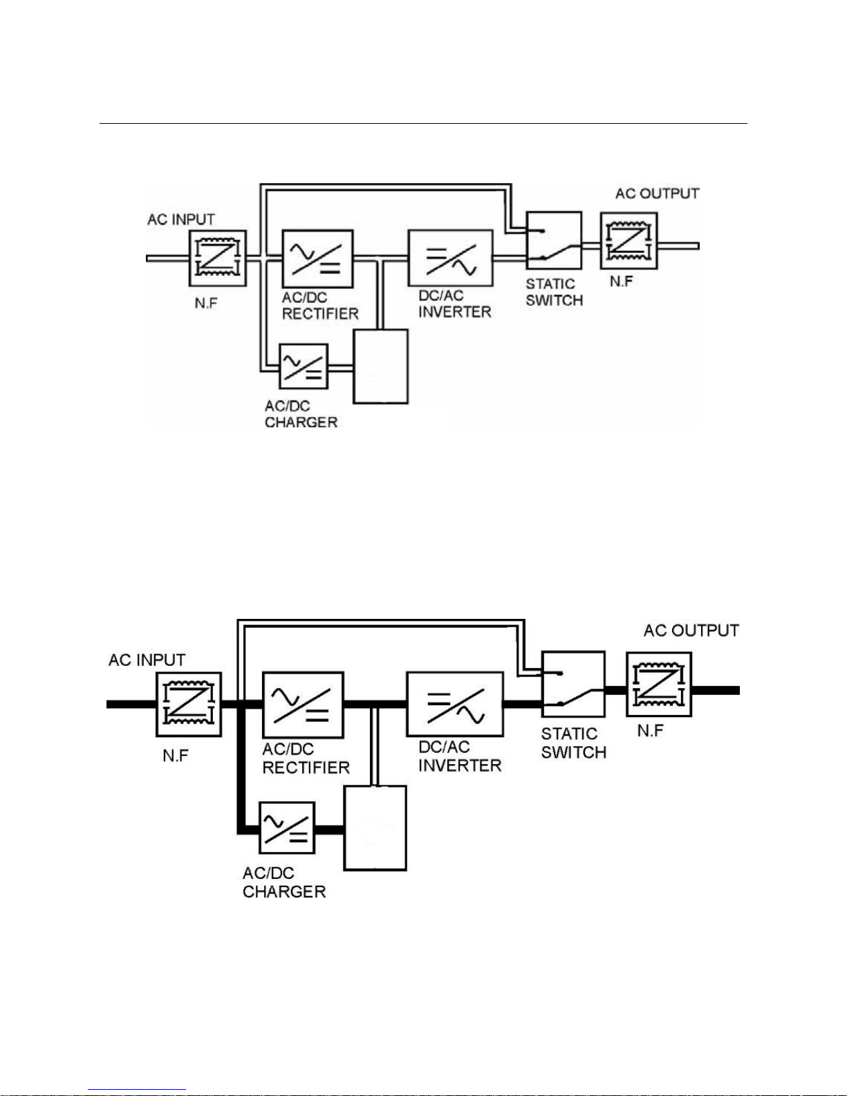
1. UPS System Block Diagram:
2. Normal Operation:
There are two main loops when AC utility is normal: the AC loop and the capacitor charging loop.
The AC output power comes from AC utility input and passes through AC/DC rectifier, DC/AC
inverter and static switch to support power to load. The capacitor charging voltage comes from
AC utility input and converted by AC/DC charger to support capacitor-charging.
ENERGY
STORAGE
MODULE
ENERGY
STORAGE
MODULE
11
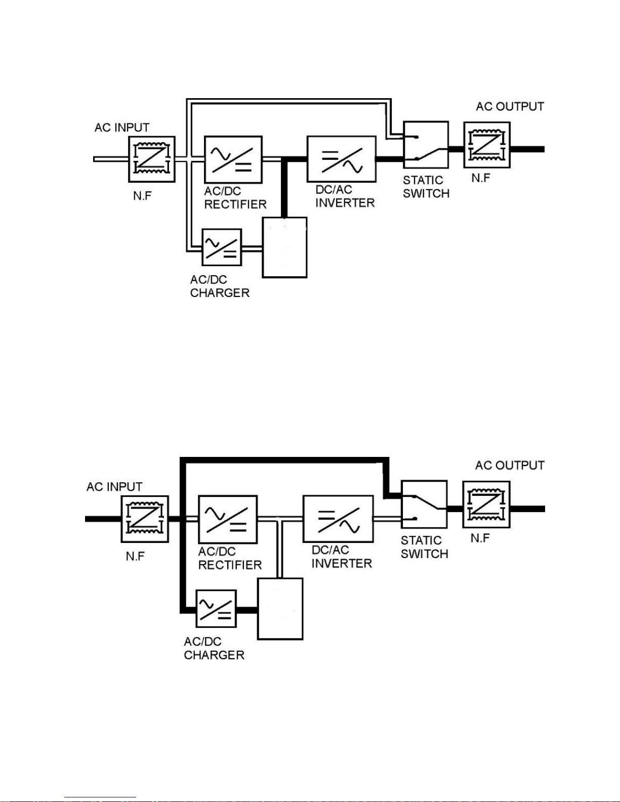
3. AC Utility Failure:
4. Bypass Enable:
Under the following conditions, the bypass will be enabled:
1. Overload.
2. Inverter failure.
3. Over-temperature.
ENERGY
STORAGE
MODULE
ENERGY
STORAGE
MODULE

12
Application Backup Time Considerations:
The backup time that a SuperCap system can supply a load depends on the useable energy
stored in the Energy Module capacitors as well as the characteristics of the load being
supported.
In order to determine if the available power produced by the SuperCap system will be adequate
for a specific application, several characteristics of the load must be known or determined.
These characteristics include:
the RMS input voltage
the load current in amps
the power factor of the load (a number between 0 and 1 )
the backup time required in seconds
The input voltage, the load current and the power factor can all be measured fairly accurately by
using an instrument such as the Fluke 43B Single Phase Power Quality Analyzer or equivalent.
As an example, a 3000VA, 2100 Watt model at either 120V or 230V provides an approximate
backup time of 15 seconds at full load, and 45 seconds at half load.
The graph below illustrates the approximate capacities and times expected for these loads:

13
Section 3: Installation
The UPS module is available in both 120V and 230v models. Be sure to connect the UPS
to the proper AC power source. Connecting the UPS to the wrong power source can cause
damage to the UPS and potential injury to the operator.
The UPS module also requires an Energy Storage Module. Use caution when connecting
the Energy Storage Module cable to the UPS Module. Do not allow the conductors on the
DC connector to make contact with any metal object or with each other.
The SuperCap UPS System contains dangerous voltage levels!
Dangerous and potentially lethal charges can remain on the capacitors of the Energy
Storage Unit even after it has been turned off and disconnected from the AC input line.
Before moving, storing, carrying out capacitor bank replacement or shipping the system.
Ensure that the Energy Storage Module capacitors are completely discharged by putting
the UPS module in backup mode.
1. With the UPS Module ON (Normal Mode) and a load connected.
2. Remove AC Input.
3. Let it run in backup mode until it shuts off all cables are disconnected.
Prior to Start Up make sure the load is disconnected or in the “OFF” position, and verify
that the input voltage meets the rating required by the UPS!
Transporting
1. Disconnect all power cables if necessary.
2. Be careful not to damage the UPS while transporting.
3. Don‘t move the UPS upside down.
4. Please transport the UPS system only in the original packaging (to protect against shock and
impact).
Positioning
1. Do not put the UPS on rugged or declined surface.
2. Do not install the UPS system near water or in damp environments.
3. Do not install the UPS system where it would be exposed to direct sunlight or near heat.
4. Do not block off ventilation openings in the UPS system’s housing and don’t leave objects on
the top of the UPS.
5. Allow a minimum distance of 10cm (3.9 inches) in the rear and two sides of the UPS for
ventilation.
4. Keep the UPS far away from heat emitting sources.
6. Do not expose it to corrosive gas.
7. Ambient temperature: 0℃ - 40℃ (32°F – 104°F).
CAUTION!
DANGER!
14
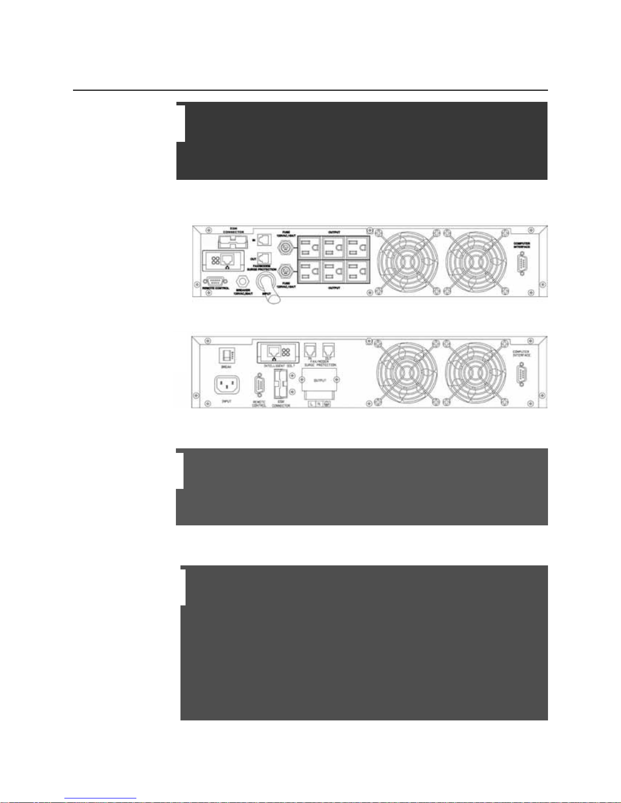
SuperCap UPS Rear Views
Electronics Module
1KVA RM-2U 120V NEMA
Electronics Module
3KVA RM-2U 120V NEMA
Electronics Module
3KVA RM-2U 230V HARDWIRE
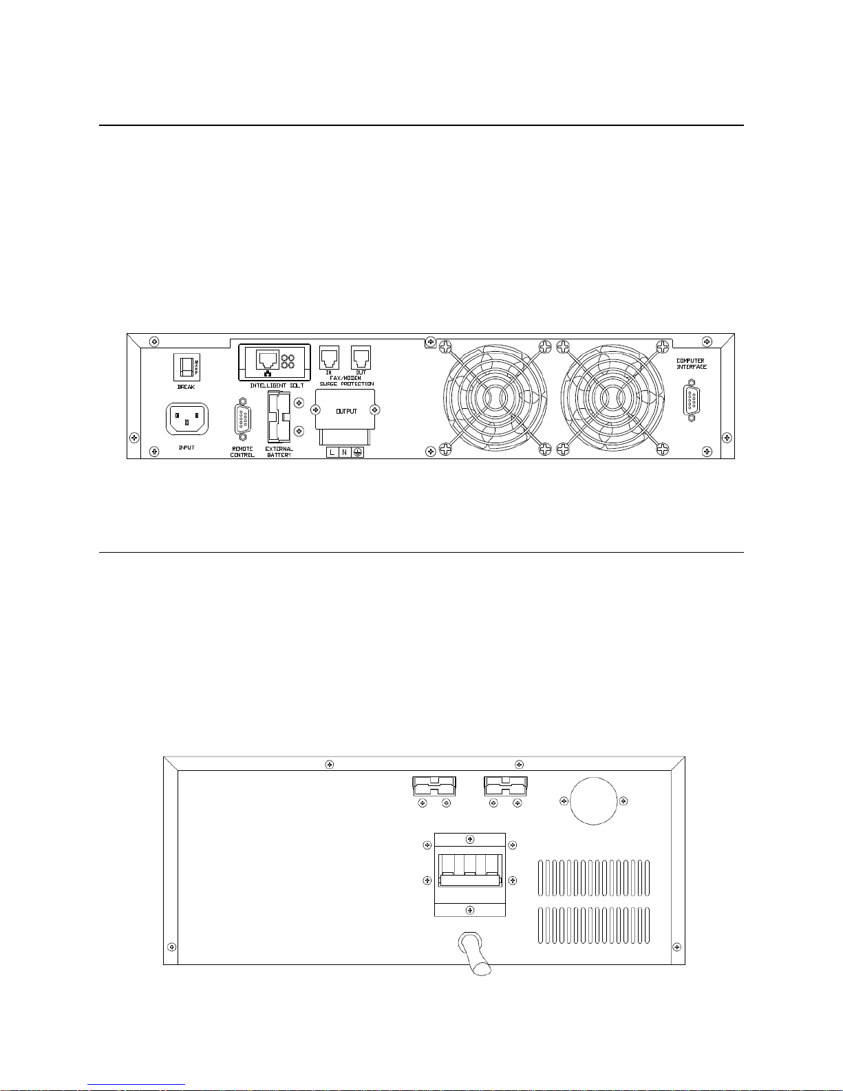
SuperCap Module
1KVA RM-2U 120V IEC
SuperCap Module
3KVA RM-2U 120V NEMA
15
SuperCap UPS Connector Layout
The SuperCap UPS Module provides three connections on the rear panel:
1. An AC line cord (used for powering and charging the unit.)
2. A NEMA type-5 (120V unit) or NEMA type 6 (230V unit) connector (used for
connecting a UPS to the AC output of the Energy Storage Module.)
3. An Anderson “Powerpole” type connector for connecting the DC-Out from the
Energy Storage Unit to the DC-In connector on the UPS.
Energy Storage Unit Connector Layout
The Energy Storage Unit provides three connections on the rear panel:
1. An AC line cord (used for powering and charging the unit.)
2. A NEMA type-5 (120V unit) or NEMA type 6 (230V unit) connector (used for connecting a
UPS to the courtesy AC output of the Energy Storage Module.
3. An Anderson “Powerpole” type connector for connecting the DC-Out from the Energy
Storage Unit to the DC-In connector on the UPS.

16
Installation
The correct installation of the UPS module requires plugging the unit into a proper AV power outlet
and also connecting the unit with an external Supercapacitor Energy Storage Module.
Connect the UPS Module and Energy Storage Module only to a grounded AV Input
Source.
Place cables in such a way that no one can step on or trip over them.
Do not disconnect the mains cable on the UPS system or the building wiring socket outlet
during operations since this would cancel the protective grounding of the UPS system
and of all connected loads.
The UPS has its own internal power source (Supercapacitor). The output terminals may
be live even when the UPS is not connected to the AC supply.
Ensure that no fluids or other foreign objects can enter the UPS system.
CABLE CONNECTION
The system should be installed and connected only by qualified electricians in accordance
with applicable safety regulations.
When installing the electrical wiring, please be aware of the nominal amperage of your
incoming feeder.
Please ensure that the incoming feeder is isolated and secured to prevent it from being
switched back on again.
When installing the UPS Module and/or the Energy Storage Module in a rack. Please
remove the rubber feet on the bottom of the respective pieces.
The SuperCap UPS System contains dangerous voltage levels!
Dangerous and potentially lethal charges can remain on the capacitors of the Energy
Storage Unit even after it has been turned off and disconnected from the AC input line.
Before moving, storing, carrying out capacitor bank replacement or shipping the system.
Ensure that the Energy Storage Module capacitors are completely discharged by putting
the UPS module in backup mode.
1. With the UPS Module ON (Normal Mode) and a load connected.
2. Remove AC Input.
3. Allow it to run in backup mode until it shuts off all cables are disconnected.
NOTE:
DANGER!

17
Step 1 - Connecting UPS Module to AC:
Option 1 – Connect the included power cord to an AC receptacle.
Option 2 – Connect the included power cord to the AC convenience port on the back of
the Energy Storage Module.
IF the Electronics Module is plugged into the AC convenience outlet located on the back
of the Supercapacitor Energy Storage Module make sure that the AC source to which the
Storage Module connects can support the combined currents that will be drawn by both
the Electronics Module and the Energy Storage Module. For example, at start-up the
Energy Storage Module can draw up to 15A RMS. The AC source must be rated to supply
this current in addition to the current required by the Electronics Module/UPS.
Step 2 - Connecting the SuperCap UPS to the Energy Storage Module:
The Energy Storage Module comes with a high-current DC output cord with a polarized connector
on each end. Check the orientation of the connectors and the DC sockets on the rear panel of
the UPS Module and the Energy Storage Module. Plug one end of the DC cord into the DC socket
on the back of the Energy Storage Module and the other end into the DC socket on the back of
the UPS Module.
NOTE:

18
Step 3 - Connecting the Energy Storage Module to AC:
The UPS also requires an Energy Storage Module. Use caution when connecting the DC input
cable. Do not allow the conductors on the DC connector to make contact with any metal
object or with each other.
Connect the attached power cord to an AC receptacle.
Step 1
Step 2
Step 3

19
Section 4: Operation – LCD Interface
Front Panel Functions
The LCD display illuminates as soon as AC line power is applied to the unit and the MAIN MENU
will be displayed.
Use the Up/Down buttons to scroll through the menu to view the available menu options.
Use the Enter key to select the option that is currently displayed.
Following is a list of functions/options available via the Main Menu of the LCD display:
Rating Spec
UPS Status
Input and Output Voltages
Input and Output Frequency
Battery Voltage and Capacity
Output Power
Unit Temperature
Event History
Bypass Range Set
Output Voltage & Frequency Adjust
The last two functions listed above, ‘Bypass Range Set’ and ‘Output Voltage & Frequency Adjust’
are UPS control functions, and are described in the following sections.

20
Operation
Check Prior to Start Up
1. Ensure the UPS is in a suitable position.
2. Check that the input cord is secured.
3. Make sure the load is disconnected or in the “OFF” position.
4. Check that the input voltage meets the UPS rating.
Operation Procedure
Please follow the instructions below for UPS operation.
1. Once the AC source is connected, the LCD Display will light up immediately to display the main
menu greeting. The Normal LED will blink to indicate that the inverter is ready to be turned on.
2. By pressing the Enter-key and the Down-key simultaneously for 3 seconds, the UPS will start
up after two beeps and the Normal LED illuminates to indicate power is coming from its inverter
to the load.
3. When the Down-key and the Up-key are pressed simultaneously for 3 seconds, the inverter
will be turned off after two beeps and the UPS is in the standby status (LCD display illuminates
and Normal LED is blinking) until the AC source is disconnected.
Prior to Start Up make sure the load is disconnected or in the “OFF” position, and verify
that the input voltage meets the rating required by the UPS!
The LCD display illuminates as soon as AC line power is applied to the unit, and the MAIN
MENU will be displayed.
CAUTION!
NOTE:
SUPERCAPACITOR UPS
SYSTEM
This manual suits for next models
1
Table of contents
Popular UPS manuals by other brands


Eaton
Eaton Ellipse ASR 450 Installation and user manual

Eaton
Eaton 9SX 6000VA Installation and user manual

Eaton
Eaton DXRT 10KS31-IN Series user manual

Eaton
Eaton Powerware 9130 user guide

Vertiv
Vertiv Liebert GXT4 Series quick start guide

Fortress Technologies
Fortress Technologies AS/400 Installation and service guide