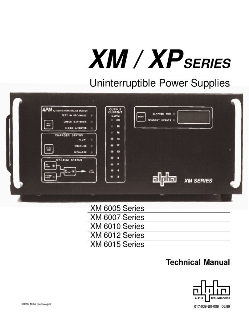
Alpha Pinnacle Plus Series User manual

Pinnacle Plus Series
6 KVA/8 KVA/10 KVA/12 KVA UPS’s
Uninterruptible Power Supplies
From Alpha Technologies
!!
!!
!Operator’s Manual

!!
!!
!Operator’s Manual
!!
!!
!Pinnacle Plus Series
6 KVA/8 KVA/10 KVA/12 KVA UPS’s
Alpha Technologies

Pinnacle Plus Series
NOTICE:
The Pinnacle Plus Series generates, uses and can radiate radio frequencies if not installed and
tested in accordance with the instructions contained in this manual. It has been tested and found to
comply with the limits established for a Class A computing device pursuant to part 15 of FCC rules
when it is operated alone. It also complies with the radio interference regulations of DOC which are
designed to provide reasonable protection against such interference when this type of equipment is
used in a commercial environment. If there is interference to radio or TV reception, which is deter-
mined by switching it on and off, relocate the equipment or use an electrical circuit other than the
one used by the Pinnacle Plus.
i
Save This Manual
It contains important installation and operating instructions.
Keep it in a safe place.
To reduce the risk of electrical shock and to ensure the safe operation of the Pinnacle Plus
Series of UPS’s, these symbols are used throughout this manual. Where they appear only
qualified personnel should carry out the instructions.
A DANGEROUS VOLTAGE exists in this area. Use extreme caution.
ATTENTION: Important operating instructions. Follow them exactly.
CAUTION
Risk Of Electrical Shock

Pinnacle Plus Series
Safety Checklists
This equipment is to be installed and operated by people trained in the safe use of
high-energy power supplies and their batteries. Also assumed is knowledge of the
local electrical code(s) and how to safely apply them.
DANGER: Sealed lead-acid batteries with high energy and chemical hazards are
used. This manual contains important operation and safety instructions. Only qualified
personnel should service the Pinnacle Plus.
Pinnacle Plus Series Safety Checklist
Carefully unpack the unit. Report any shipping damage at once.
Read this manual. If you have any questions about the safe installation, operation or main-
tenance of this unit, contact Alpha Technologies’ customer service department.
Before installation, confirm the voltage and current input requirements of the load(s) is
compatible with the unit’s output. Also see the line voltage and current is compatible with
the unit’s input requirements.
Install the unit on a dedicated circuit.
All wiring must meet the local electrical code(s).
Place a warning label on the utility panel to tell emergency personnel an Uninterruptible
Power Supply (UPS) is in the building.
Use proper lifting techniques when moving the unit.
The unit has more than one live circuit. AC power may be present at the outputs even if the
unit is disconnected from line power.
ii
DANGER: Do not expose the unit to rain or moisture.

Pinnacle Plus Series
iii
Safety Checklists (Continued)
Battery Safety Checklist
There are dangerous voltages inside the unit. Only qualified people should perform instal-
lation and maintenance.
Live battery wires must not touch the unit’s chassis or any other metal objects. This can
cause a fire or explosion.
Inspect the batteries once a year for signs of cracks, leaks or swells. Replace as required.
When batteries are in storage, charge them at least once every three months for
optimum performance and to extend their lifetime.
Always replace batteries with ones of identical type and rating. Never install old or un-
tested batteries.
Use insulated tools during servicing.
Remove all rings, watches, jewelry or other conductive items before working inside the
unit.
Follow local regulations for battery disposal. Recycling is the best method.
Never burn batteries to dispose of them. They may explode.
Never open the batteries. The contents are toxic.
Battery Emergency Procedures:
If electrolyte splashes on your skin, immediately wash the skin with water. If electro-
lyte gets into your eyes, wash them for at least 10 minutes with clean water or a
special neutralizing eye wash solution. Seek medical attention at once.
Neutralize spilled electrolyte with special neutralizing solutions in a “spill kit” or a
solution of 1 lb. of bicarbonate of soda in 1 gallon of water.

Pinnacle Plus Series
iv
Table of Contents
1. Introduction ......................................... 1
1.1 The Pinnacle Plus Advantage ................... 2
1.2 Unpacking and Inspection Checklist ......... 3
1.3 The Pinnacle Series ................................. 5
2. Installation ............................................. 8
2.1 Pre–Installation Checklist ......................... 9
2.2 Wiring the Unit ......................................... 9
2.3 Connecting External Battery Packs ....... 10
2.4 Connecting an Emergency Power Off Switch
......................................................... 11
2.5 Connecting the RS–232 Port .................. 12
2.6 Network Connection ............................... 12
3. Operation ............................................ 13
3.1 Turning the Unit On and Off .................... 14
3.2 Using the Control Panel ......................... 15
3.3 Self Test ................................................. 16
3.4 Setting the Parameters .......................... 16
3.5 Troubleshooting ...................................... 19
3.6 Battery Replacement ............................. 20
3.7 Specifications ......................................... 21
Warranty ...................................... 22

1
Section 1
Introduction
This section introduces you to the
Pinnacle Plus series of UPS’s:
• The Pinnacle Plus series many advantages
(Section 1.1).
• An unpacking and inspection checklist
(Section 1.2).
• An tour of the units, their connectors,
switches and control panels (Section 1.3).

1 Introduction 2
Alpha Technologies
1.1 The Pinnacle Plus Series Advantage
The Pinnacle Plus series is an indoor Uninterruptible Power Supply (UPS) that uses advanced
technology to protect computer networks, telecommunications installations and other vital instru-
ments from power line disturbances.
The Pinnacle Plus series uses a double conversion circuit and a digitized microprocessor to
provide continuous power to the loads. It offers complete protection against brownouts, spikes,
sags, voltage transients and frequency changes.
!AutomaticShutdown/Restart
The Pinnacle Plus series shuts down when the batteries are discharged, preventing damage
to the unit. When line power is requalified, the Pinnacle automatically restarts, providing
power to the loads and recharging the batteries.
!RS–232Communication
The Pinnacle Plus series can be remotely monitored and controlled.
!LCD/LED Display Panel
The LCD/LED display provides “at-a-glance” monitoring.
!Battery Charge Display
The LCD shows the battery % charge, battery backup time and battery voltage.
!Load Display
The LCD shows the unit’s % loading and the loading in watts and VA.
!AutomaticBypass
When the Pinnacle Plus detects an internal fault such as deep battery discharge or an over-
load, it automatically uses its built-in bypass circuit to switch the load to line power.
!Fully Digitized Microprocessor Controlled
Pure sine wave output with less than 3% THD.
!Cold Start
If there is no line at the input, the Pinnacle automatically provides battery power to the load.
!Load Shedding
The power management software allows less important equipment to be turned off during
power outages to save battery power for the critical loads.

31 Introduction
Alpha Technologies
1.2 Unpacking and Inspection Checklist
TIP: If items are missing or damaged, contact Alpha and the shipping company at
once. Most shippers have a short claim period.
Carefully remove the unit from its shipping container. Inspect it for damage and make sure the
following items are included:
One Pinnacle Plus series UPS with pre-installed batteries.
One operator’s manual.
One power cord.
One Alphamon CD-ROM.
One RS–232C interface cable.
Any ordered options.
Save The Original Shipping Container
If you need to return the unit for servicing, pack it in the original shipping
container. Alpha is not responsible for damage caused by the improper
packaging of returned units.
Read This Manual
Before installation, become familiar with your unit by reviewing the
procedures and drawings in this manual. If you have any questions
about the safe installation, operation or maintenance of the unit, contact
Alpha’s customer service department.

1 Introduction 4
Alpha Technologies
1.2 Unpacking and Inspection Checklist (Continued)
Complete the following for your records
Serial # __________________________________
Options __________________________________
Purchase Date ____________________________
This Pinnacle Plus was purchased from
Dealer ___________________________________
City _____________________________________
State/Province _____________________________
Zip/Postal Code ___________________________
Country __________________________________
Telephone # _______________________________
Fax # ____________________________________
E Mail ___________________________________
For emergency technical support 7 days a week / 24 hours a day call:
USA: 1–800–863–3364
CANADA: 1–800–667–8743
For technical support contact Alpha Technologies customer service department directly at:
:setatSdetinU 0632-746)063(
:adanaC 6741-034)406(
:modgniKdetinU 011224-9721-44+
:ynamreG 0-98897-2219-94+
:tsaEelddiM 57657-352-753+
:ailartsuA 0233-2279-2-16+
Table of contents
Other Alpha UPS manuals
Alpha
Alpha FlexPoint FPR1207-F User manual
Alpha
Alpha Novus FXM 1100 User manual
Alpha
Alpha XM2-300HP User manual
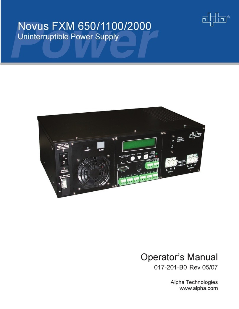
Alpha
Alpha Novus FXM 1100 User manual

Alpha
Alpha Novus FXM 650 User manual
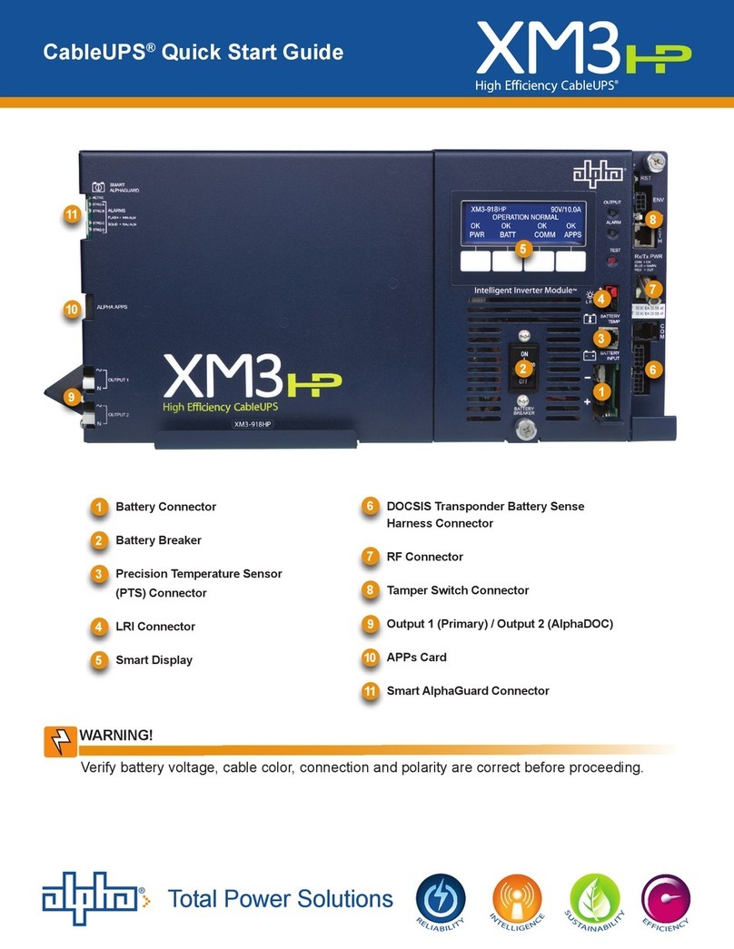
Alpha
Alpha XM3 User manual
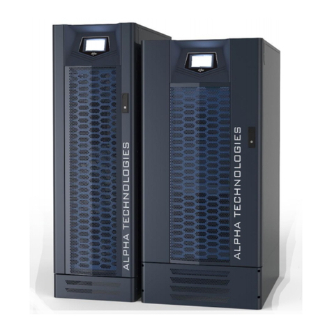
Alpha
Alpha Tri Power X33 TE User manual

Alpha
Alpha Novus FXM 650 User manual
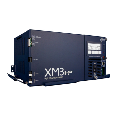
Alpha
Alpha XM3-HP Series User manual
Alpha
Alpha FP1208-F-5A User manual


