Marine Air Systems ECU-Maxx User manual

PAGE 2
ECU-Maxx VER:10a 12/1/97
ECU-M
AXX
O
PERATIONS
M
ANUAL
Table Of Contents
INTRODUCTION............................................................................................................. 3
SYSTEM FEATURES ...................................................................................................... 3
Solid State Fuses .................................................................................................... 4
OPERATOR CONTROLS & DISPLAY PANEL ........................................................................ 5
Power Button........................................................................................................... 5
MODES OF OPERATION ................................................................................................. 7
FAN OPERATION .......................................................................................................... 8
BASIC OPERATION ....................................................................................................... 9
PROGRAM MODE ....................................................................................................... 11
Entering Program Mode .........................................................................................11
Restoring Factory Default Settings ........................................................................11
Using Program Mode ............................................................................................ 12
Exiting Program Mode........................................................................................... 12
Software Identification........................................................................................... 12
PROGRAMMABLE PARAMETERS ..................................................................................... 12
Soft Start Ramp Delay .......................................................................................... 18
De-Icing................................................................................................................. 19
PROGRAM TABLE ....................................................................................................... 20
THEORY OF OPERATION .............................................................................................. 21
ECU-Maxx System Timing .................................................................................... 21
SYSTEM TIMING DIAGRAM ........................................................................................... 22
SYSTEM INPUTS AND OUTPUTS .................................................................................... 23
FAIL-SAFE AND FAULT HANDLING ................................................................................. 25
FAULT HANDLING & FAIL-SAFE MODES ............................................................................ 26
416 OPTION BOARD .................................................................................................. 27
TYPICAL APPLICATION ................................................................................................. 28
SPECIFICATIONS......................................................................................................... 29
FACTORY PROGRAMMING OPTIONS F-1 THROUGH F-8................................................... 30
REVISION HISTORY .................................................................................................... 31
Copyright © 1995 Micro Air Corporation, All Rights Reserved
No part of this publication may be reproduced, translated, stored in a retrieval system, or transmitted on any form or by
means electronic, mechanical, photocopying, recording or otherwise without prior written consent by Micro Air
Corporation
Every precaution has been taken in the preparation of this manual to insure its accuracy. However, Micro Air Corpora-
tion assumes no responsibility for errors and omissions. Neither is any liability assumed for damages resulting from the
use of this product and the information contained herein.
PAGE 3
ECU-Maxx VER:10a 12/1/97
ECU-M
AXX
O
PERATIONS
M
ANUAL
I
NTRODUCTION
The ECU-Maxx (Environmental Control Unit) is a full featured reverse cycle
heatpumpcontrollerformarineHVAC.Theunitconsistsofonedisplaycontrol
head and a remote high voltage system control module. The system has been
designed for easy installation and solid state operation. The following pages
describe both operation and user-defined parameters available on the ECU-
Maxx.
S
YSTEM
F
EATURES
AC Voltmeter TheECU-Maxx's hardware includes an AC voltmeterwhich is used to monitor
and display line voltage. These readings represent the voltage at the control
module, not at the electrical panel. The line voltage feature is the first item
accessed in the View Mode.
AC Amp Meter The ECU-Maxx's hardware includes an AC Amp meter to monitor power
consumption.Suddenchangesinpowerrequirements(current)usuallyindicate
problemswiththesystem.For instance, increasedcurrentdrawcanmeana loss
ofcoolingwater,compressororelectricalproblems.Thesystemamperageisthe
second item accessed in View Mode.
Dual Voltage Capability
Line voltage is recognized on power-up by the ECU-Maxx and the unit
automatically adapts to the voltage applied. This feature eliminates the need to
stock two separate voltage controls.
WARNING! Dual voltage only applies to the control unit itself, not to the
equipmentitisconnected with.Thesystemorcoolingassemblymustmatchthe
line voltage supplied.
Start Capacitor RelayTheECU-Maxxprovidescircuitrytosimplifytheconnectionofthecompressor
start capacitor to the system. This feature eliminates the complicated wire
harnessandrelayassociatedwithconventionalstartcapacitorandrelaycircuits.
Face Plate Air Sensor
The ambient air temperature sensor is located in the display panel. This face
plate air sensor produces the best results in most installations; however, the
display must be located on an inside wall at eye level.
NOTE: The display should not be subjected to direct sunlight. The alternate
(remote) air sensor should be used if these conditions cannot be met.

PAGE 4
ECU-Maxx VER:10a 12/1/97
ECU-M
AXX
O
PERATIONS
M
ANUAL
Ambient Light Sensor
Thedisplay panel is equipped with an ambient light sensor (photodiode) which
automatically controls the display brightness. This feature allows maximum
visibility in very bright conditions while maintaining adequate but subdued
brightness in the dark.
Non-Volatile EEPROM Memory
Operatingandprogrammed parametersareentered intononvolatilememory.If
powerislostforanyreason,allsettingsandparametersareretainedindefinitely,
with no battery or electrical power required. When AC power is restored, the
ECU-Maxx will resume operation exactly where it left off, even if it is years
later.
Fan Speed Compensation
When AC line voltage falls, the lower fan speeds are gradually increased to
prevent fan motor stalling. This option helps maintain constant fan speeds
during low dock voltage conditions.
Power Failure Recovery
The ECU-Maxx features automatic shutdown and restart during "brown out"
conditions. The system is programmed to shut down after 5 (five) minutes of
continuous low line voltage. The unit will automatically restart when the line
voltage returns to normal.
Compressor Soft Start
The ECU-Maxx may be configured with an optional Compressor Soft Start
feature.Thecompressor softstartfeaturehasbeendevelopedinordertoreduce
the starting load placed on the electrical system by the compressor. This option
is installed at the factory and must be ordered specifically.
Solid State Fuses
The ECU-Maxx monitors the system current before and during any electrical
component used to protect all systems from shorts or excessive loading. The
solid state fuse system is capable of automatic recovery from electrical
problems.Thiseliminatestheneedtomanuallyreplacefuses.Thecircuitryalso
protects the components from problems relating to high current, such as: a
locked rotor, loss of cooling water, or other compressor-related problems.

PAGE 5
ECU-Maxx VER:10a 12/1/97
ECU-M
AXX
O
PERATIONS
M
ANUAL
O
PERATOR
C
ONTROLS
& D
ISPLAY
P
ANEL
PleaserefertoFigure1,below,forthelocationofthebuttonsanddisplayslisted
on the following pages:
1. POWER button The power button is used to switch the ECU-Maxx between Off Mode and On
Mode, enter Program Mode and reset the Factory Default Values for the
programmable parameters.
2. FAN SPEED buttonThe fan speed button is used to switch between the automatic and manual fan
features and is also used to select the fan speed when in Manual Fan Mode.
3. UP button TheUpbuttonisusedtoincreasethetemperaturesetpointvalue,andtoincrease
the value of programmable parameters when the ECU-Maxx
is in Program Mode.

PAGE 6
ECU-Maxx VER:10a 12/1/97
ECU-M
AXX
O
PERATIONS
M
ANUAL
4. DOWN button The Down button is used to decrease the temperature set point value, and to
decrease the value of programmable parameters when the ECU-Maxx is in
Program Mode.
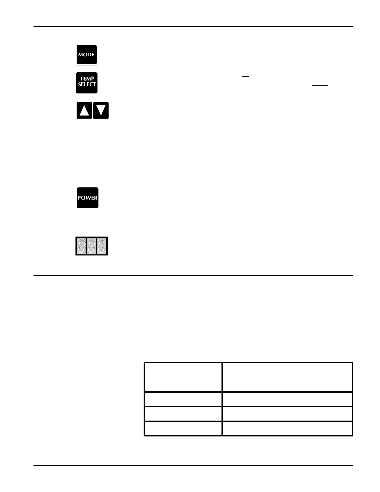
5. MODE button The Mode button is used to switch between the various modes of operation of
the ECU-Maxx. The modes are AUTO, HEAT, COOL and MOISTURE
CONTROL. This button is also used to scroll up through the programmable
features in Program Mode.
6. TEMPERATURE SELECT button
The Temperature Select button is used to choose which temperature will be
displayedonthe3-digitLEDDisplay.ItisalsousedtoentertheViewModeand
to scroll down through the programmable features in Program Mode.
7. Three Digit Display
This3-digit7-segmentLEDdisplayisusedtodisplaytemperatureinformation,
programinformation,voltage,current orfaultcodes,dependingupon themode
selected by the user or the fault detected by the ECU-Maxx. The decimal point
to the far right on this display is used to indicate when the compressor is on.
8. HEAT MODE light The heat mode indicator LED will be lit when Heat Mode has been selected.
9. COOL MODE light The cool mode indicator LED will be lit when Cool Mode has been selected.
10. AUTOMATIC MODE light
The automatic mode indicator LED will be lit when Auto Mode has been
selected. Auto Mode allows for automatic heating and cooling.
11. MOISTURE CONTROL MODE light
The moisture control indicator light will be illuminated when Moisture Con-
trol Mode has been selected
12. MANUAL FAN light
The Manual Fan indicator LED will be lit when Manual Fan Mode has been
selected.
13. AUTOMATIC FAN light
The Automatic Fan indicator LED will be lit when Automatic Fan Mode has
been selected.
14. FAN SPEED INDICATOR BAR GRAPH display
The Fan Speed indicator bar graph is composed of six LEDs. These LEDs are
lit in direct proportion to the fan speed, with 1 LED on being Lowest Fan speed
and all LEDs on being Highest Fan speed. This display is operational in both
Auto and Manual Fan modes.

PAGE 7
ECU-Maxx VER:10a 12/1/97
ECU-M
AXX
O
PERATIONS
M
ANUAL
15. INSIDE AIR TEMPERATURE light
When the Inside Air Temperature indicator LED is lit, the 3-digit display will provide a readout of the
insideairtemperatureasdetectedbytheinsideairsensor(locatedonthefaceplateunlessthealternate
air sensor is installed).
16. OUTSIDE AIR TEMPERATURE light
When the Outside Air Temperature indicator LED is lit, the 3-digit display will provide a readout of
the outside air temperature as detected by the outside air sensor.
17. SET POINT light
When the Set Point indicator LED is lit, it indicates that the 3-digit display is showing the current
temperature set point. This value can be adjusted with the Up and Down buttons.
18. COMPRESSOR ON light
Whenthelast decimalpointofthe7-segmentLEDdisplayislit,itindicates thatthecompressoroutput
is active.
M
ODES
OF
O
PERATION
Off Mode
When the ECU-Maxx is in the Off Mode, all control outputs will be turned off. All programmed
parametersandusersettingswillbesavedinnonvolatilememory.ProgramModecanonlybeaccessed
in the OFF Mode.
On Mode
When the ECU-Maxx is in the On Mode, power will be supplied to the appropriate control outputs,
and the displays will indicate the current state of operation. This was the state stored the last time the
unit was on.
Note: If the unit is being turned on after an interruption of power, this is considered a power-on reset
condition. All lights on the display will flash for one second before normal operation is resumed.
Cool Only Mode
When the ECU-Maxx is configured to be in Cool Only Mode, only the cooling system will be used as
needed.
Heat Only Mode
When the ECU-Maxx is configured to be in the Heat Only Mode, only the heating system will be
activated as necessary.
Automatic Mode
When the ECU-Maxx is configured to be in the Automatic Mode, both heating and cooling will be
supplied as needed. (The HEAT and COOL indicator LEDs will be lit, showing which system is
currently in operation.)
PAGE 8
ECU-Maxx VER:10a 12/1/97
ECU-M
AXX
O
PERATIONS
M
ANUAL
Temperature Hysteresis
Temperature is automatically maintained within the programmed temperature
rangeofthesetpoint.Forexample,thefactorydefaultvalueforthetemperature
hysteresisis2º: Whenthetemperaturerequirementhasbeensatisfied,a2ºshift
is required to establish demand. A 4º shift is required to change from one mode
totheother.Oncetherequiredheatingorcoolingmodehasbeenestablished,the
hysteresis remains 2º.
Moisture Control Mode
When the ECU-Maxx is configured for Moisture Control Mode, the system
maintains a preset temperature and humidity range. These ranges are program-
mable.
F
AN
O
PERATION
Auto Fan Mode AutomaticfanmodeallowstheECU-Maxxtodeterminethefanspeedbasedon
ambient room temperature. The closer the temperature is to the set point, the
slower the fan speed. This permits a balance between the most efficient
temperature control and slower (quieter) fan speeds.
Manual Fan Mode Manual fan mode allows the customer to set the fan speed manually.
View Mode ViewModeisoneoftheServiceModes.Viewmodeallowstheusertoexamine
system voltage, current, inlet water temperature, total compressor run time, HI
and LO Pressure Switch status and the AC line Hz.
Program Mode ProgramModeis one ofthe ServiceModes.Programmodeallowstheuserto
change any of the 34 program settings.
To Turn the Unit On Press the Power Button once. This toggles the ECU-Maxx from Off Mode to
On Mode. The panel displays will light, indicating that the unit is ready for
operation. If the unit is being turned on after an interruption of power, all lights
onthedisplaypanelwillturnonfor1secondpriortoresumingnormaloperation.
To Turn the Unit Off Press the Power Button once to toggle the ECU-Maxx from On Mode to Off
Mode.
Note:Thefanwillremainonfor4(four)minutesaftertheECU-Maxxisturned
off if heat was being supplied by the Optional CAL Rod Heater.
Selecting Cool Only Mode

PAGE 9
ECU-Maxx VER:10a 12/1/97
ECU-M
AXX
O
PERATIONS
M
ANUAL
Repeatedly press the Mode button until the Cool Mode indicator LED is on, and cooling will be
supplied when required.
Selecting Heat Only Mode
Repeatedly press the Mode button until the Heat Mode indicator LED is on, and heating will be
supplied when required.
Note:If the water temperature is below the lowwater limit, the valve and compressor will turnoff and
heat will be supplied by the optional CAL rod heater, if installed.
B
ASIC
O
PERATION
Setting Automatic Mode
RepeatedlypressingtheModebuttonuntiltheAutoModeindicatorLEDison
places the ECU-Maxx in Automatic Mode, and heating or cooling will be
suppliedasneeded.InadditiontotheAutomodeLED,theCoolandHeatLEDs
will be lit when the unit is cooling or heating.
Setting Moisture Control Mode
Byrepeatedlypressingthe ModebuttonuntiltheMoistureControlindicator
is on places the ECU-Maxx in the Moisture Control Mode. Minimum and
maximum temperatures as well as humidity levels are controlled in this mode.
All parameters are user-programmable.
Adjusting the Set Point
TheSetPointshouldbe set to thedesiredroomtemperature,astheECU-Maxx
willmaintaintemperaturetowithintwodegreesofthe set point. The maximum
setting for the set point is 85º F. The minimum setting for the set point is 60º F.
To change the Set Point:
Pressing the Up or Down buttons when the ECU-Maxx is in the On Mode
forces the display to show the set point (the Set Point indicator LED will be lit)
and will raise or lower the set point. The speed at which the set point changes
increases with the time the button is held down. The numbers change slowly at
first,thenrapidlyincreaseasthebuttonremainsdepressed.Whentheupordown
button is released, the display will return to its previous state.
Fan Operation The Fan Control maintains 6 (six) fan speeds, which are indicated by the Fan
Speed Bar Graph on the control panel. The fan speeds are equally divided with
1 LED lit being Low Fan and 6 LEDs lit being High Fan.
When the ECU-Maxx is placed in Automatic Fan Mode, the fan speeds will
vary according to the difference between room temperature and set point. The
fartherroomtemperatureisfromthesetpoint, the faster the fan will run. As the
setpointisapproached,thefanspeedsarereduced,culminatinginlowfanspeed
at the set point. A 6º spread between set point and room temperature produces
high fan speed. The fan speed is reduced one number for every 1º reduction in

PAGE 10
ECU-Maxx VER:10a 12/1/97
ECU-M
AXX
O
PERATIONS
M
ANUAL
temperature differential. This speed reduction does not take place until the
temperature differential between the ambient temperature and the set point is
less than 6º (six degrees).
The maximum temperature differential may be increased from 6º to 12º by
changing the programmable parameter Automatic Fan Speed Spread. The
increaseinthespreadfrom 6º to 12ºresultsinonefanspeedreduction for every
2º decrease in temperature. When programmed in this mode, high fan speed is
used only in extremely hot conditions. Once the room is cooled down, condi-
tions requiring high fan speed are less likely to recur.
Setting Automatic Fan Mode
To place the fan in AutomaticMode, press and release the FanSpeed button
until the Auto indicator LED is turned on.
Setting Manual Fan Mode
To place the fan in Manual Mode, press and release the Fan Speed button.
This toggles the fan control from Automatic to Manual modes. Pressing and
holding the Fan Speed button will cause the fan speed lights to scroll 1 (one)
through 6 (six) and then back to 1. Releasing the Fan Speed button when one
of these fan speed lights are on will set the fan speed to that number.
Example: Releasing the button when the third LED is on will set a Manual fan
speed of 3 or medium.
Note: Selecting 1 through 6 results in a manual fan speed setting and lights the
manuallamp.Thefanspeed will notvaryfromthissettingbut will becorrected
for low line voltage.
Setting Fan Only Mode
With the ECU-Maxx in OFF Mode, press and release the Fan Speed button
to turn the fan on. Press and hold the Fan Speed Button to set the desired fan
speed asindicated on theFan Speed BarGraph.The ECU-Maxx willenter Fan
OnlyorCirculationMode.OnlytheFanSpeedBarGraphisilluminatedduring
Circulation Mode. Pressing the Fan Button cancels the Fan Only Mode and
returns the unit to the OFF Mode.
Note: Automatic fan speeds are not available in Fan Only Mode. Manual fan
speedsselectedpertaintotheFanOnlyModeanddonotaffectthepre-selected
fan speeds in Heat, Cool or Auto Modes.
Entering View Mode Press and hold the Temp Select button for 2 (two) seconds, then release the
button. Use the Up and Down buttons to scroll through the various items that
maybeviewed.Amnemoniccodeforthevaluebeingdisplayedisflashedalong
with the value in view mode. The following items are available for display in
View Mode:
PAGE 11
ECU-Maxx VER:10a 12/1/97
ECU-M
AXX
O
PERATIONS
M
ANUAL
1. AC Line Voltage (Voltmeter) (code "AC")
2. AC Amperage (Ammeter) (code "cur")
3. Water Sensor (code "H2O")
4. Total Compressor Run Time (in hours) (code "crt")
5. Freon Low Pressure (code "L-P")
6. Freon High Pressure (code "H-P")
7. AC Line Frequency (50 or 60 Hz) (code "FrE")
Exit View Mode by pressing the Temp Select Button. This will return the unit
to normal operation. The ECU-Maxx will exit View Mode automatically if no
buttons are pressed for 1 (one) minute.
P
ROGRAM
M
ODE
Program Mode is a mode in which many of the operating parameters may be
adjusted. The ECU-Maxx is shipped with Factory Default settings of these
programmable parameters (see Factory Default Settings section) which are
stored in permanent memory, and can be recalled at any time.
Note: Severe electrical disturbances can sometimes upset the ECU-Maxx's
operating sequences. Operator confusion related to program parameters can
also cause what seem to be operational problems.
WheneverthereisanydoubtastotheproperoperationoftheECU-Maxxcontrol
unit, factory default parameters should be initialized.
Entering Program Mode
Program Mode can only be entered from OFF Mode. From Off Mode, press
and hold the Power button for 5 (five) seconds until a "P" appears in the
display. Release the Power button and the characters "P-1" followed by a
parameter value will appear in the display. The ECU-Maxx is now in program
mode.
Note: The ECU-Maxx will exit program mode and return to the OFF Mode if
no programming is attempted for 1 (one) minute.
Restoring Factory Default Settings
InitializeFactoryDefaultSettingsbypressing and holding thePowerbutton
for 10 (ten) seconds when the ECU-Maxx is in the OFF Mode.
Five (5) seconds after the button is pressed, "P" appears in the display. At 10
(ten) seconds, the letters "IP" appear, indicating the initialization process has
been completed. Releasing the button momentarily displays the Software
Version Number (for example "A0.X"). The ECU-Maxx will return to the
OFF Mode.
PAGE 12
ECU-Maxx VER:10a 12/1/97
ECU-M
AXX
O
PERATIONS
M
ANUAL
Using Program ModeThe program parameters are displayed by pressing the Mode button or the
Temp select button. Program parameters are designated by "P-nn" in the
display, where "nn" is a number from 1 to 34. Pressing the Mode button
repeatedlywillcausethedisplaytoscrollupthroughalltheprogramparameters.
Pressing the Temp Select button will cause the display to scroll down through
all the program parameters.
The Up and Down buttons are used to select the data or set the desired limits
for the parameter being programmed.
Select Option ON or Option OFF using the Up and Down buttons. This
method is followed throughout Program Mode; however, special instructions
areincludedinthesectionProgrammableParametersforindividualfunctions
that require them.
Exiting Program Mode
There are two methods to exit program mode. Press the Power button and the
ECU-Maxx returns to the OFF Mode. Not pressing any button for 60 (sixty)
seconds will cause the control unit to exit Program Mode.
Software Identification
The software version is identified for 1 (one) second prior to the exit from
ProgramMode.Thesoftwarenumberwillappearinthedisplayforonesecond,
then the display turns off.
P
ROGRAMMABLE
P
ARAMETERS
The 34 programmable parameters along with their Factory Default Settings are listed in at the end of this
section. The following are definitions and operating theory for all the programmable functions of the ECU-
Maxx.
P-1: Moisture Control Mode Dehumidification Level
Moisture Control Mode contains a dehumidification cycle to help prevent mildew and conserve energy.
ExampleofDehumidification Level1: Every4hours,the fanisstarted andairis circulatedfor30 minutes.The
air temperature is sampled and re-
membered. Cooling is started and
willcontinueuntilthetemperatureis
lowered2º.Fourhourslater,thecycle
startsover.However,thiscycledoes
not conflict with the minimum or
maximum temperature settings.
The Humidity cycle will not start
untilthemaximumorminimumtem-
peraturerequirementshavebeensat-
isfied. Dehumidification can be programmed at one of three levels, as shown in Table 2, above. The factory
default setting for this function is Level 1 (2°).
ECU-Maxx
Program Setting Reduction in Temp Before
Cooling is Stopped
12°F
2 4°F
3 6°F

PAGE 13
ECU-Maxx VER:10a 12/1/97
ECU-M
AXX
O
PERATIONS
M
ANUAL
P-2: Moisture Control Mode High Temp Set Point
This function sets the minimum cooling temperature that will be maintained in
Moisture Control Mode. The range for this value is between 95º F and 77º F.
The room temperature where the ECU-Maxx display panel is located (unless a
remote air Temp. Sensor has been installed) will not be allowed to exceed the
temperature selected by this set point. Use the Up and Down buttons to select
the temperature. The factory default value of this setting is 85º F.
P-3: Moisture Control Mode Low Temp Set Point
This function sets the maximum heating temperature that will be maintained in
Moisture Control Mode. The range for this value is between 50º F and 69º F.
The room temperature where the ECU-Maxx display panel is located (unless a
remoteairtemperaturesensorhasbeeninstalled)willnotbeallowedtogobelow
thetemperatureselectedbythissetpoint.UsetheUpandDownbuttonstoselect
the temperature. The factory default value of this setting is 55º F.
P-4: Cycle Pump With Compressor
The pump output can be configured in one of two ways:
Off selects continuous operation of the pump when the ECU-Maxx is on.
On selects the function to allow the pump to cycle with the compressor. This
setting reduces pump wear by cycling the pump with the heating or cooling
demandonly(factorydefaultsetting).Inthismodethepumpwillcontinuetorun
for 2 minutes after the compressor cycles off.
P-5: Temperature Display Units
Program mode ºF selects degrees Fahrenheit (ºF).
Program mode ºC selects degrees Celsius (ºC).
IMPORTANT!Alltemperaturefunctionswillbebasedonwhateversystem(F
or C) is selected. ºF is the factory default setting.
P-6: Temperature Calibration
Use this feature to calibrate the air sensor within a range of ±10º.
Enter Program Mode and the current calibration offset will be displayed. Use
the Up and Down keys to set the desired number.
P-7: Cycle Fan With Compressor
Normally, the fan remains on all the time; however, this option allows the fan
to cycle off when the demand for heating or cooling is satisfied.
Off selects continuous operation of the fan (factory default)
On selects cycle fan with compressor. In this mode the fan will shut off 5 to
135 seconds after the compressor, depending on the value for the compressor
start delay.

PAGE 14
ECU-Maxx VER:10a 12/1/97
ECU-M
AXX
O
PERATIONS
M
ANUAL
P-8: High Fan Speed Limit
Theupperlimitofthefanspeedcanbereducedtotailorthefanoutputforvarious
motors.Therangeofvaluesforthehighfanspeedare50through80inarbitrary
units. The high fan limit is not permitted above 220 VAC to prevent excessive
fan noise.
UsetheUpandDownbuttonstoselectthefanspeedpreset.Thefactorydefault
setting of this function is 70.
P-9: Low Fan Speed Limit
ThelowfanlimitdeterminesthelowestoutputallowedforLow Fanspeed.The
range of values for the low fan speed are 25 through 49 in arbitrary units.
UsetheUpandDownbuttonstoselectthefanspeedpreset.Thefactorydefault
value of this function is 40.
P10: Fan Motor Select
The fan motor select option provides separate low line voltage corrections for
two basic types of motors used in most systems. This option does not select the
fan speed tables for fan speeds 1-6. High and low fan speed limits must be
adjusted for each fan.
SP selects the shaded pole fan option (factory default)
SC selects the split capacitor type fan.
P11: Automatic Fan Speed Spread
Automatic fan speeds are directly related to temperature reduction in cooling
andtemperatureincreasesinheating.Therearetwooptionsavailable:1ºspread
per fan speed or 2º spread per fan speed. In cooling, the fan speeds increase as
the temperature exceeds the set point. In heating, the fan speed increases as the
temperature decreases in relation to the set point. In both cases, the fan speed
increases as the temperature differential between set point and room tempera-
ture increases.
1programs 1º per fan speed. This will bring the fan up to high speed when the set
point is 6º from the room temperature. This is the factory default setting.
2programs 2º spread per fan speed. High fan will be generated at an 12º
difference between set point and actual temperature.
Note: High fan speed is not likely to recur after the set point has been reached on
initialstart-upinmode2.Thisoptionisprovidedtohelpreduceoverallsystemnoise
by minimizing operation at or near high fan speed.
P12: Automatic Fan Speed Heating Option
Becauseofthemanyinstallationvariables,highheadpressurecanbeaproblem
in the heating mode. To help reduce head pressure, the automatic fan speed
operation can be reversed in the heating mode. In other words, the fan speed
increases as the set point is approached in heating mode. The fan speed spread
option applies to this option.

PAGE 15
ECU-Maxx VER:10a 12/1/97
ECU-M
AXX
O
PERATIONS
M
ANUAL
P13: High Water Limit
Thehighwaterlimitdefinestheavailabilityofcoolingwaterforthecondensercoil.
The water pump and compressor are not allowed to operate above the high water
limit. High water temperatures at the condenser inlet usually indicate a lack of
cooling water. Temperatures at or above the high water limit are indicated by
alternately flashing "H-I" and then "H2O" in the display. Fail-safe protection
levels apply to the high water limit.
The range of the high water limit is 100º F to 150º F, with 140°F being the factory
default value. Use the Up and Down buttons to select the high water limit.
High water limit readings are taken with the compressor running and are
compensated for sensor location which is outside the Freon circuit. Since
cooling water flows inside the Freon circuit, the settings must be appropri-
ately high.
P14: Low Water Limit
Thelowwaterlimitdefinestheavailabilityofheatinthecondenserwater. Heating
canonlyoccurattemperaturesabovethelowwaterlimit.Thecompressorandwater
pump are not allowed to operate below the selected low water limit. Temperatures
at or below the low water limit are indicated by alternately flashing "L-O" then
"H2O" in the display. Fail-safe protection levels apply to the low water limit.
IftheoptionalCALrodheaterisinstalled,theECU-Maxxwillautomaticallyswitch
to the CAL rod heater when the water temperature is below the limit. The LO / H2O
warning will not be displayed when the CAL rod heater is installed!
The range for the low water limit setting is 40º F through 60º F. 50°F is the factory
defaultsettingforthisfunction.UsetheUpand Downbuttonstoselectthelowwater
limit.
Lowwaterlimitreadingsaretakenwiththecompressorrunningandarecompensatedfor
sensor location which is outside the Freon circuit. Since cooling water flows inside the
Freon circuit, the settings must be appropriately low.
P15: Service / Water Sensor Option
The Service/WaterSensorisusedtomonitortheWaterTemperaturegoingthrough
the compressor condenser coils. The Service / Water Sensor jack is located on the
416OptionBoardandmustbeprogrammedONifitisinstalled.P13andP14require
the Service / Water Sensor be installed!
P16: High Pressure Switch Option
ThecircuitboardisequippedwithapairofFastonsforahigh-pressureFreonswitch.
This software option can be turned off when the switch is not used or for trouble
shooting purposes.
P17: Low Pressure Switch Option
A pair of Fastons are supplied for an optional low Freon pressure switch. This
softwareoptioncanbeturnedoffwhentheswitchisnotusedorfortroubleshooting
purposes.

PAGE 16
ECU-Maxx VER:10a 12/1/97
ECU-M
AXX
O
PERATIONS
M
ANUAL
P18: High Pressure Freon Switch Disable
ThisoptionhasbeenprovidedtodisableHighPressureFaultsinheatingmodeonly,
since high head pressure can be an acceptable occurrence while heating. This
function is only valid if P16 is enabled.
P19: Low Pressure Freon Switch Hold-Off Delay
Low Freon pressure conditions can occur during normal operation. To prevent
erroneous LP faults from occurring a hold-off delay is provided. A low Freon
pressure event that lasts longer than the delay time will cause a Low Pressure fault
to occur.
The minimum delay is 60 seconds. The delay range is 1 to 15 minutes, in 1
minuteincrements. Use theUpand Down buttons to program thedesired hold-
off delay. The factory default setting is ten [ 10 ] minutes.
P20: CAL Rod Heater Option
Optional output is provided for an electric strip heater which is placed in the
blower housing. This strip heater is referred to as a CAL rod heater. This
software option is provided to turn the output on when the heater is installed.
P21: Compressor Start Delay
The compressor start delay is included for use in installations where more than
one system is being operated from the same power source. The start delay can
besetatdifferentintervalsforeachcontroltoallowonlyonecompressortostart
at a time. The units should be staged at least 5 seconds apart.
The minimum delay is 5 seconds. The maximum delay is 135 seconds. Use the
Up and Down buttons to set the delay.
P22: Low Voltage Threshold
TheLowVoltageThresholddefinesthevoltagewherethecompressoristurned
off. The fault code "L-O" then "A-C" will flash alternately with the line
voltage in the display.
This function allows the ECU-Maxx to be used on a wide variety of line
voltages. The allowable low voltage threshold range is 75 VAC through 100
VACfor115Voltunits,and175VACthrough200VACfor220Voltunits.Use
the Up and Down buttons to select the low voltage threshold. The voltage will
appear in the display and represents the actual line voltage.
P23: Sustained Low Voltage Shut Down
OFF - A continued low line voltage condition for 15 seconds will cause the
compressortoturnoffwhilethefaultcode"LO-AC"alternatelyflasheswiththe
line voltage in the display. After 4 successive failures, the system requires a
manual restart. (See Fail-safe Chart for each level action)

PAGE 17
ECU-Maxx VER:10a 12/1/97
ECU-M
AXX
O
PERATIONS
M
ANUAL
ON - A continued low line voltage condition for 5 minutes will cause the compressor to turn
offwhilethefaultcode"LO-AC"flasheswiththelinevoltageinthedisplay. After4successive
failures the system requires a manual restart. (All Fail-safe Levels)
Torestart ECU-Maxxmanually, press the Power buttonto reset the unit to the OFFMode.
P24: Fail-safe Protection Level
Fail-safe protection is offered at three levels, as enumerated in the table above.
Example: If the ECU-Maxx is in cooling mode and the high water limit is
exceededformorethan10seconds,thepumpandcompressorwillbeshutdown
to prevent burning the motors out.
Note: Four consecutive shutdown events will lead to a sustained system
shutdown.TheECU-MaxxcanberesettotheONModebypressingthePower
button once.
P25: Temperature Hysteresis
Temperature Hysteresis is defined as the difference allowed between set point
andactualroomtemperature.Whenthisdifferenceisexceeded,theECU-Maxx
will call for heating or cooling as required.
The 4º spread required to switch from automatic heating or cooling is not
affected by this option. The 4º spread is provided to prevent the control from
oscillating between heating and cooling while in Auto Mode.
The ECU-Maxx can be configured to provide 2º, 3°, 4º, 5° or 6º of hysteresis.
P26: System Current Limit
The ECU-Maxx limits the current supplied to the components attached to it.
This parameter sets the maximum current available to the power outputs. The
valid range of values is 5 to 40 Amperes. The factory default is 35 Amperes. If
the unit is operating at 220 VAC, current limit is half the displayed value.
Failsafe
Protection
Level
Action Description of Action Taken by ECU-Maxx
1
Displa
y
fault onl
y
!
MINIMUM PROTECTION LEVEL:
Air Sensor Fault: Heatin
g
/Coolin
g
immediatel
y
suspended; normal
operation not resumed until fault cleared. Fault displa
y
: "A IR "
Low Volta
g
e Fault: ECU-II will react accordin
g
to how Low Volta
g
e
Shutdown pro
g
rammed.
NO OTHER FAILSAFE PROTECTION PROVIDED.
2
Displa
y
fault & shut
down compressor
with continuous
restarts.
INTERMEDIATE PROTECTION LEVEL:
All actions taken in Failsafe Protection Level 1 Plus:
In addition, the FAULT CODE messa
g
e will be displa
y
ed but
NO ACTION WILL BE TAKEN b
y
the ECU-II.
3
Displa
y
fault &
re quire manual reset
after 4 failures.
MAXIMUM PROTECTION LEVEL:
FAULT CODE messa
g
es are displa
y
ed and the appropriate action is
taken, accordin
g
to the problem encountered.

PAGE 18
ECU-Maxx VER:10a 12/1/97
ECU-M
AXX
O
PERATIONS
M
ANUAL
P27: Soft Start Ramp Delay
Thecompressorsoftstartfeatureisafactory-installedoptionontheECU-Maxx,
developed to reduce the electrical loading placed on the system when the
compressor starts up. If soft start has been installed on your system, the Soft
Start Ramp Delay Option will adjust the ramp time from 0 to 5 seconds (see
system timing diagramin the SystemControlalgorithmsection).The factory
default setting is 2 seconds.
Use the Up and Down buttons to adjust this setting.
P28: Self Test
The diagnostic self test is included to help verify proper operation of the ECU-Maxx. Upon
entering the TestMode, the following items are checked in the order shown. During the output
checks, "P-28" and "ON" will flash in the display
Select ON to enter Test Mode. The following items are performed in the order
below. During the test, "P-28" and "ON" will flash in the display.
1.EEPROM Memorytest: Shouldthistestfail,alldashes:"---", willbedisplayedand
the test will not continue.
2.Air Sensor Test: Thefaceplateairsensoristestedandthetemperature displayed.
Ifthesensorisdefective,"AIR" willflashcontinuouslyinthedisplay.Agoodsensor
will display the correct ambient temperature.
3. Lamp Test: All LEDs are turned in for 3 seconds and then turned off.
4.Alternate AirSensorTest: Ifinstalled,thealternateairsensoristestedinthesame
manner as the face plate sensor.
5. Water Inlet Sensor Test: The water inlet temperature sensor is checked and should
displaythecorrectwatertemperature,assumingthatithasbeenproperlyinstalled.Afailed
watersensortestwillcontinuously flash "H2O" in thedisplay.
6. Fan Test: The fan is started and brought up to speed. Each fan speed is tested for
5 seconds.
7. Valve Test: The valve is cycled on for 5 seconds and then turned off.
8. Pump Output Test: The pump is turned on for 5 seconds and then turned off.
9. Compressor Test: The compressor output is turned on for 10 seconds and then
turned off.
10. Firmware Version will be displayed and then the display will blank out.
Self test can be cancelled at any time by pressing the Power Button. When the
Self test is completed ECU-Maxx will exit to the OFF mode.
P29: Outside Air Option
When this option is turned ON, the Alternate Air input jack is used as an
outside air sensor input.
PAGE 19
ECU-Maxx VER:10a 12/1/97
ECU-M
AXX
O
PERATIONS
M
ANUAL
P30: Station ID Number
Used to identify the control's placement when connected with the Lan-Maxx
network option.
P31: Winterization System Option
This option is used when there is no sea water available. With this option ON,
the sea water pump is disabled and Heat is provided by an Electric Heater
ONLY. Provides electric heat in colder climates or when the boat is out of the
water.
P32: No Reverse Cycle Heating
This option is for cooling only units without reversing valves. An optional
electric heater (CAL Rod Heater) must be installed if heating is required.
P-33: De-Icing This option is designed to periodically deice the evaporator coil when low fan
speed has been selected. A two minute De-Icing Cycle is performed each hour
the thermostat does not detect reduction in cabin temperature. Once the first
cycle is initiated low fan speed is increased by one number to help prevent
further icing.
P-34: Outside Air Temperature Sensor Calibration
This feature is used to calibrate the outside air sensor plus or minus 10 degrees
Fahrenheit.
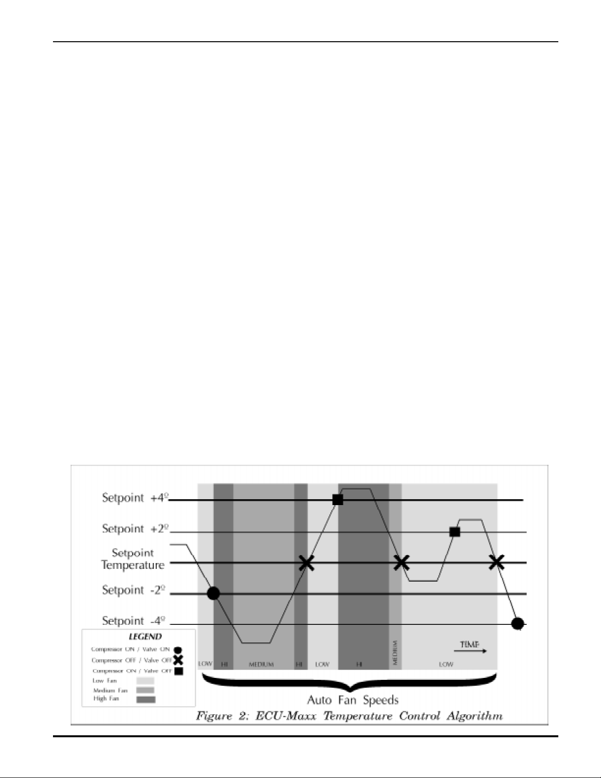
Temperature Control Algorithm
Note: Heating mode shown with automatic fan speeds reversed, i.e. P-12 ON
… fan speed increases as set point is approached.

PAGE 20
ECU-Maxx VER:10a 12/1/97
ECU-M
AXX
O
PERATIONS
M
ANUAL
P
ROGRAM
T
ABLE
Prog
Num
Programmable Parameter
Factory Default
Settings Permitted Values or Ranges
P-1 Moist Cntrl Mode Dehumidification Level Level 1 1,2 or 3
P-2 Moist Cntrl Mode High Temp Set Point 85º F
77ºF to 95ºF / 23°C to 35°C
P-3 Moist Cntrl Mode Low Temp Set Point 55º F 50º F to 69ºF
P-4 Cycle Pump With Compressor
Off = Continuous On = Pump Cycles With Comp.
On = Pum
p
w / Com
p
.On = Pum
p
With Com
p
.
O ff = C o ntinuo us P um
p
P-5 Temperature Display ºF or ºC ºF °F / °C
P-6 Temperature Calibration (Used to Cal. Inside Air Sensor) 0º -10º to +10º
P-7 Cycle Fan With Compressor
On = Fan With Compressor Off = Continuous Fan Off = Continuous Fan
On = Fan C
y
cles With C om
p
.
Off= Continous Fan
P-8 High FanSpeed Limit (arbitrary units) 70 50 to 80
P-9 Low FanSpeed Limit (arbitrary units) 40 25 to 49
P10 Fan Motor Select SP = Shaded Pole
SC = Split Capacitor
Shaded Pole SP SP or SC
P11 Automatic Fan Speed Spread (Speed Change per °F) 1º 1º or 2º
P12
Reverse Automatic Fan S
p
eeds Durin
g
Heatin
g
On = Fan S
p
eed Increases as Set Point is A
pp
ro ac he d in Hea tin
g
Off = NormalOperation On / Off
P13 High Water Limit (Compessor must be running!) 140º F
100ºF to 150°F 37.8° C 65.6°C
P14 Low Water Limit (Compessor must be running!) 50º F
40º to 60º F 4.5° to 15.5°C
P15 Water Sensor Option (Option Board Required) Off On / Off
P16 High Pressure Switch Option (Compessor must be running!) On On / O ff
P17 Low Pressure Switch Option (Compessor must be running!) O n O n / O ff
P18 High Pressure Freon Switch Disable [Heating Mode Only] On On / Off
P19 Low Pressure Freon Sw. Hold-Off Delay 10 min 1 to 15 Minutes
P20 Cal Rod Heater Option (Option Board Required) Off On / Off
P21 Minimum Compressor Start Delay 5 seconds 5 sec. - 135 sec.
P22 Low Voltage Threshold Protect 85V (110VAC)
185V (220VAC)
75 - 100 VAC
175 - 200 VAC
P23 Sustained Low Voltage Shutdown
Off = 15 Second Delay On = 5 Minute Delay Off On / Off
P24 Failsafe Level 3 1, 2 or 3
P25 Temperature Hysteresis 2º F 2º, 3°, 4º, 5° or 6º Fahrenheit
P26 System Curent Limit 35 Amps 5 - 40 Amps
P27 Compressor Soft Start Delay (Factory Installed Option) 2 sec 0 - 5 sec
P28 Self Test Off On / Off
P29 Outside Air Sensor Option Off On= Air Sensor Installed
Off= No Sensor Installed
P30 Station ID # for Lan-Maxx Network 0 0 - 40
P31
Winterized
Allows Electric Heat O
p
eration Without Sea The Water Pum
p
O ff = N o rmal O
p
eration On / Off
P32
No Reverse C
y
cle Heatin
g
Use In C old W ater W he re C AL R od Electric H eat Is Installe d
O ff = Reverse C
y
cle
Heatin
g
O n = N o Reve rse C
y
cle Heat
Off= Reverse C
y
cle Heatin
g
P33
AntiIcin
g
C
y
cle (Periodic Reverse C
y
cle O
p
eration Prevents Ice From
Formin
g
On Eva
p
orator C oil) Off On = AntiIcin
g
Enabled
Off= AntiIcin
g
Disabled
P34 Calibrate Outside Air Sensor 0°F -10°F to +10°F
Table of contents
Other Marine Air Systems Marine Equipment manuals


