STARGAZER Wake Edition Stern Drive User manual

2/23/2023
StarGazer - Wake Edition
Stern Drive
February 2023

2/23/2023
Table of Contents
Page No.
Section 1 Using StarGazer Wake Edition 1
Wakeboard Speed Mode 1
Setting KDW 2
Section 2 Using RPM Mode 3
Section 3 Using Slalom Mode 4
Course Timing (No Mag Timing) 4
Section 4 Using Name List 6
Section 5 Other Display Features 7
Screen Contrast 7
Quick Reference Guide on Moving Through Menu 7
GPS Info – Setting Clock 7
Switch to MPH<>KPH (User Settings) 7
RPM Tach Reading Not Correct (User Settings) 7
Section 6 Driving Tips 8
Section 7 Trouble Shooting 9
System Reset 11
Linkage Test 11
Servo Motor Test 11
Section 8 Installation 12
GPS Receiver 14
Tip: To adjust contrast on LCD Screen, Press MENU and UP Keys together.
See Page 7.
1
Section 1 Initial System Start Up
The very first time your PerfectPass is turned on, it may ask you two questions:
1. “Initial Hours 000”. If this hour meter feature is present, use the UP Key to enter
the number of hours on your boat. PerfectPass will start counting from that
position. Press MENU Key to continue.
2. [ Read in MPH ^ = Yes ] If you want your system to display in MPH, press the
Up Key. For metric, press the Down Key.
3. [ WAKE EDITION ^ = YES ] Press UP Key to confirm Wake Edition software.
USING STARGAZER WAKE EDITION
There are three operating modes to choose from: (1) Wakeboard Mode is speed based
and controls from the GPS Sensor; (2) RPM Mode allows the user to set an RPM value;
and (3) Slalom Mode allows slalom skiers to enter a speed for open water skiing and
course skiing.
The ON/OFF key is pressed to turn control ON or OFF. System should always be in OFF
mode when not in use. Turning system ON or OFF is always done at neutral or at idle for
safety. You may be asked to confirm you are in neutral as follows [ IN NEUTRAL ^ =
Yes ]. Press UP Key to confirm.
Typically, wakeboarders prefer the pull characteristics of the speed based Wakeboard
Mode. This mode is designed for 9 – 30 mph.
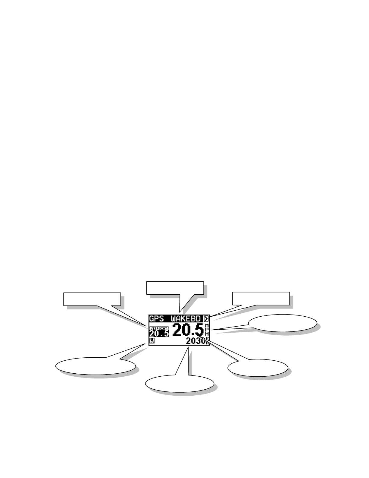
Wakeboard Mode (Speed Based)
When system is ON, the screen will appear as above with set point speed at left. By using
Menu Key you can move around the screen and highlight set point to make speed
changes.
Menu Arrow
Name/Mode
SETPOINT
Speed Base
Speed
Tachometer
Mode Indicator

2
Once desired speed has been set, you can simply pull up the rider and when set point has
been reached or exceeded the system will engage and take over automatically. (You will
hear an audile beep and “WAKEBD” heading will become highlighted to confirm
engagement.
To disengage system, pull back on the throttle.
The key to good driving is to smoothly drive to engagement speed so PerfectPass can
seamlessly take control. If you have a heavily laden boat and need full throttle from start,
slowly pull back on handle as speed increases to help PerfectPass engage smoothly.
If the rider falls, pull throttle back and system will disengage. Return slowly to rider and
pull them back up. PerfectPass will once again engage when set speed is reached.
Menu Arrow – To move to another mode, use menu key to highlight Menu arrow in
upper right corner and press up key to confirm. The following screen will appear with
other operating modes you can select.
KDW Adjustable Pull Parameter – This background setting allows you to tailor the
pull characteristics. To access, highlight Menu Key , and press the DOWN Key to
access this KDW screen:
KDW (Throttle Pull Rate) – KDW can be changed using up or down keys. The higher
the value, the more aggressive the control. Heavy boats may need higher values. Factory
setting is about 80. Normal range is 40 – 120. (If this value is set too high, the control
may become a little erratic and engagement may not be as smooth). Some boats may
need a lower value if control is not smooth.
Down Key for
access to KDW
Use MENU Keyto
highlight desired Mode
and press UPKey
UP Keyto
selectMode

3
Section 2 RPM Mode
USING RPM MODE
In this mode, the screen will appear as follows:
Operating in this mode is very similar to using the Wakeboard or Trick modes, except the
system is now controlling to an RPM SETPOINT.
RPM DRIVING
Prior to towing the rider / skier, select the RPM SETPOINT by using the UP or DOWN
keys with the SETPOINT highlighted on the screen. Pull the rider up smoothly and
continue to accelerate up to or beyond the RPM SETPOINT so the system can engage
and take control. The digital tachometer should match the RPM set point.
Changes can be made to the RPM SETPOINT while the system in engaged (“on the fly”)
to fine-tune the RPM you desire.
2. Menu Arrow
1. SETPOINT
Speed Base
Speed
Tachometer
Mode Indicator

4
Section 3 Slalom Mode
1. Select Slalom Mode. Simply set your speed and go.
2. If you wish to time your passes in a slalom course, you must “MAP”
the course.
3. You can select speeds in 1 mph (1.5 kph) increments. The official
speeds in MPH are: 24.9, 26.7, 28.6, 30.4, 32.3, 34.2, 36.0
4. The only adjustment to the pull is a value called “Pull Factor” found
by highlighting the Menu Arrow > in upper right corner, then press
UP KEY. The word SLALOM is now highlighted, press DOWN
KEY for “Pull Factor”. Standard is 50, a higher value is more
aggressive. (Range is 25–100). We do not expect that you will need
to adjust this.
5. Timing – If you “MAP” your course, the screen will show your Ball 3
and full course times as you exit the course.
Wake Edition - Course Mapping (No Magnet Timing)
Step. 1 Locate “Map Courses” on your screen.
Highlight the arrow and press DOWN Key.
Step. 2 You will see where you have the ability to Map Three (3) Courses. To
enter the coordinates for the first course highlight line 1. Press the UP
Key to select Course 1.
Use MENU KEY to highlight the course
you wish to map & press UP to select.

5
UP Key at DOWN Key at Entrance in opposite
Entrance direction (Entry 2)
(Entry 1)
Note: Only the entrance gates from each direction will be “mapped”.
Step. 3 Starting at one end of the course, idle the boat towards and through the
entrance gates. As you pass through the gates and the gate buoys are
parallel to the engine box, press the UP KEY. (Entry 1) The display will
beep to confirm coordinates are locked. (See Figure A).
Drive to the other end of the course, turn boat around and idle back
through the entrance gates into the course and press the DOWN KEY
(Entry 2) as the gate buoys pass the engine box. The display will beep.
(If you made an error you can simply repeat the procedure, press the UP
or DOWN KEY again and it will overwrite the original coordinates).
Figure A
Course #1 is now mapped and you are finished.
Use MENU Key to proceed.
MENU Arrow
To leave this screen, use MENU Key to
highlight MENU arrow and press UP Key.
If you wish to Map another course, highlight course #2 and press UP. Repeat procedure.
E
E
6
Section 4 Using Name List
Additional PerfectPass features are accessed by pressing the MENU & UP keys together.
The features available vary depending on the make and model of your boat. If a feature
is not present on your PerfectPass then it is not available on your system. To move to the
next feature press the MENU key.
NAME LIST
This version of PerfectPass allows you to store up to four names and their preferred
speed. The Name List can be accessed by pressing the UP key when the NAME/MODE
section is highlighted or by going into the SUBMENU and selecting the Name List.
Once in the Name List press the MENU key to move through the list. With the desired
name highlighted press the UP key to select the name from the list and load their settings
or press the DOWN key to edit the name.
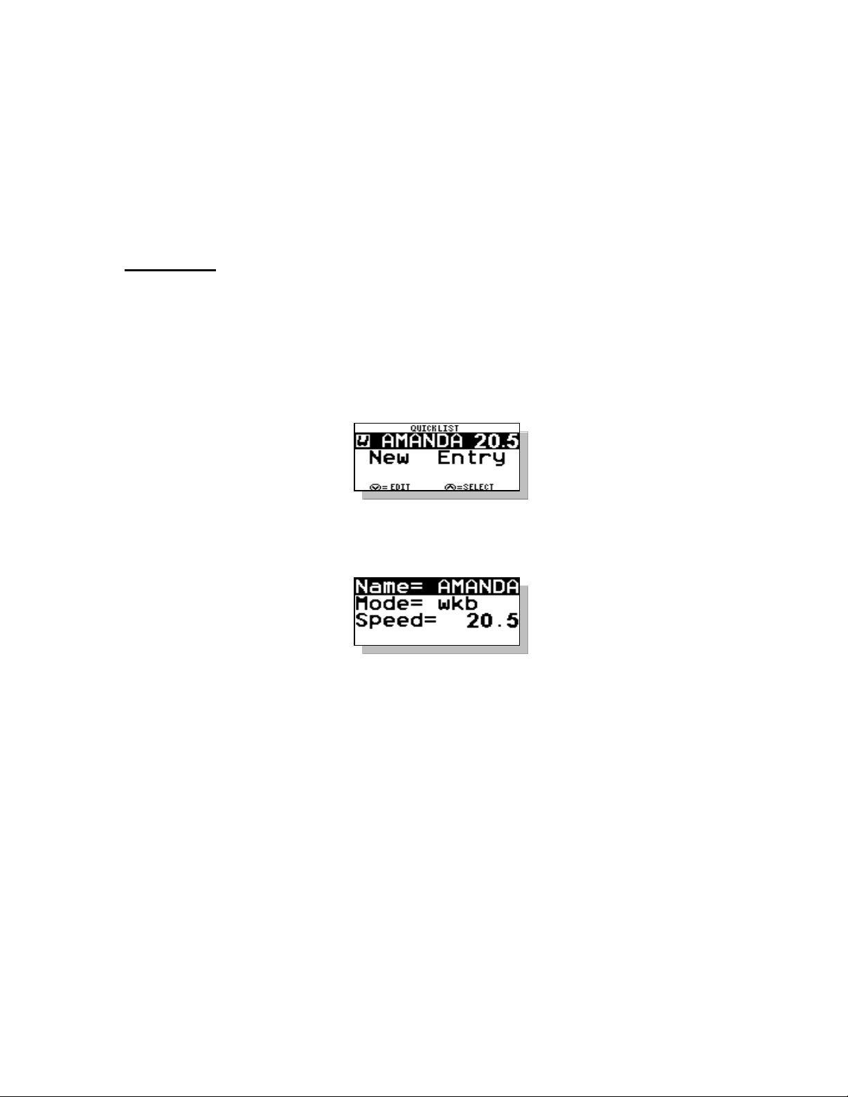
Creating Names – First enter the Quick List. Press the MENU key until [NEW
ENTRY] is highlighted. Then press the UP key to enter a new name. The following
screen will then appear:
Scroll through the alphabet using UP & DOWN keys, and then press MENU to move to
next position. Press the MENU key to move through the settings. If you are
programming a JUMP or SLALOM name there will be another page of settings to enter.
Deleting/Editing Names – As you scroll through list of names, instead of pressing UP
key to select that name, press the DOWN key to edit or delete.
Note: Names can be changed by “Editing Names” but can only be deleted by performing
“System Reset”.

7
Section 5 Other Features
If you press the Menu & Up keys together you will access the following.
To move to the next feature press the Menu Key.
CONTRAST – By pressing the UP or Down Keys you can adjust the contrast level. (3 is
normal).
BACKLIGHT – You can adjust the strength of the backlight.
QUICK LIST – You can access the Name List here.
SYSTEM INFO – This screen will display the software version, Battery Voltage and
Hour Meter.
CONTROL SETTINGS – Applicable to “Drive by Wire” systems only.
DEVICE TEST – Here you can check the Servo Motor and Wiring. (See Servo Motor
Phase Test under “Troubleshooting” at www.perfectpass.com and associated video.
USER SETTINGS – Switch between MPH<>KPH. You can also select Engine Type
(V8<>V6) and RPM Inversion.
GPS INFO/CLOCK – On this screen, press the UP or Down Keys to set the clock for
your region in the world.
The Clock will need to be set for your region of the world.
MORE THROTTLE MESSAGE – In the event the screen shows this message, advance
the handle a bit until the message disappears. The system requires additional throttle
cable in order to maintain control.
Indicates GPS locked on
satellite.
Set clock for your
region by pressing
UP or Down Key

8
Section 6 Driving Tips
1. Always pull a rider up smoothly. If you accelerate too far past the target speed,
you can gently pull the throttle handle back to assist PerfectPass in taking control.
When PerfectPass engages you will hear an audible “beep”. In addition when
engaged the Modes (Wakeboard) or Name on Screen will become highlighted.
2. Always leave your hand on the throttle and keep an eye on the lake ahead. Pull
back throttle to neutral to stop boat. (The system will immediately disengage and
the boat will be under manual control).
3. When returning to a rider in the water, drive very slowly and carefully. Always
turn engine off when loading or unloading a rider from platform. Never back a
boat up when someone is in water behind.
4. “More Throttle” If you see the “More Throttle” message on the screen, this means
PerfectPass is running out of control room, press throttle handle slightly ahead
until the message disappears.
5. You can temporarily over-ride the system by applying more throttle. The engine
speed will increase for about 5 seconds before PerfectPass regains control.

9
Section 7 Troubleshooting
Detailed Trouble Shooting documents and videos can be found on line at
www.perfectpass.com . See Support, “Trouble shooting”.
Common Questions & Answers
1. Condition:
New System - high idle on start-up.
Solution:
There is a “gap” at the Brass L-Adapter. See install pics or call PerfectPass for
“High Idle Document”.
2. Condition:
In Wakeboard Mode under heavy load system is surging after engagement.
Solution:
If it is smooth without load, but surges a bit under heavy load then the KDW may
be too high. (The response to speed change is too aggressive). Try lowering
KDW until control is smooth. (Normal range 15 – 90).
3. Condition:
In both Wakeboard & RPM mode the system beeps to engage, but boat speed
never settles in and “hunts” above & below Set Speed.
Solution:
It appears that the PerfectPass throttle cable does not have free movement and is
rubbing against engine cover or some other obstacle. A Linkage Test should be
performed. See Page 11.
4. Condition:
System beeps to confirm engagement, but boat continues past set speed and never
locks in.
Solution:
Computer is attempting to control, but servo not responding. A Servo Motor
Test/Linkage Test should be performed. (Servo motor could be seized). See Page
11.
5. Condition:
PerfectPass back light in display is on, but no data on screen.
Solution:
Press the Up or Down Key. If there is a “beep” then the master module is ON.
LCD may be a problem. Contact PerfectPass.

10
6. Condition:
PerfectPass has no digital speed reading.
Solution:
1. Check Master Module to ensure GPS cable is properly connected and pins
are in proper position and not bent.
2. Does main screen show “No GPS Data”? If so, it does not see the GPS
connected or GPS is defective.
7. Condition:
Boat speed drops and throttle handle must be pushed far down to get acceleration.
Solution:
Servo motor is not holding and rotating properly usually due to a bad connection
at the servo motor. See Servo Motor Test, Page 11 and Servo Phase Test at
support@perfectpass.com.
8. Condition:
System is blowing the 5 amp, 1.25” fuse on 12 V power cable.
Solution:
Generally caused by a short or “grounding” problem with the red 12 V power
cable on servo motor. Closely inspect wiring particularly around gold resistor.
(Remember, resistor & servo motor will run very hot which is normal). If all
looks OK, unplug everything from master module except display. Slowly start re-
connecting one cable at a time to isolate which device is causing the “short”.
9. Condition:
Set in KPH but want MPH
Solution:
Press Menu and UP Keys together. Go to User Settings and switch.
10. Condition:
My digital tach reading is wrong.
Solution:
Go to User Settings (Menu and UP Keys together) and go to “Engine Set Up”.
You can switch to V-6, etc.
11. Condition:
LCD is not clear.
Solution: Try adjusting contrast. Menu & UP Keys at same time.

11
SYSTEM RESET
Turn key ON and quickly press and hold “ON/OFF” and “Menu Keys” together for about 5 seconds until
[ SYSTEM RESET ^ = YES ] appears. Answer the questions including YES to [Wake Edition Only ^ =
YES].
LINKAGE TEST
This test should confirm whether the PerfectPass throttle cable & linkage connection is properly working.
With key OFF, turn black knob on servo motor in clockwise direction until snug. (This is the normal start
position of the knob). It should always return to this position when returning to neutral. Now push the
manual throttle to 1/2 open position. Now take black knob on servo and slowly turn the knob in a
counterclockwise direction, and then in a clockwise direction.
As you rotate the knob back & forth, you should see the throttle lever on engine opening & closing very
smoothly with each step of the motor. As you turn the knob counterclockwise which lets out cable, the
throttle will close back towards neutral. When you rotate it clockwise the throttle will open .
As you rotate the knob back and forth (slowly and quickly), the throttle should open & close very smoothly
and the brass L Adapter at linkage should be rotating as well to follow cable. At no point should the
throttle cable catch, hook or come into interference with any part that could disrupt the cable movement.
If the cable is rubbing against a decorative engine cover, fuel rail, motor box etc, adjust servomotor and
cable to improve alignment. Many plastic decorative engine shrouds can cause this problem. Remove
temporarily and run boat if you suspect this could be a problem.
Final Test: With key OFF, push manual throttle to full open position. Watch PerfectPass throttle cable to
ensure it can move freely without binding or interference.
Throttle Return Spring: PerfectPass can open the throttle (by turning clockwise), but relies on the engine
return spring to close the throttle when the servo turns counterclockwise. (The return spring is always
applying pressure against the throttle back towards the neutral position). If the servo turns
counterclockwise to slow the boat, but the throttle lever on engine does not move or moves very slowly, the
return spring could be weak, broken, etc.
If you feel the spring is weak or damaged, an external return spring can be added.
Servo Motor Test / Auto Tighten Test
Every time you return the boat to neutral when PerfectPass is on, the servo will wind in the cable until snug
in a clockwise direct. This is the normal starting point for the servo.
Each time you turn the key on or start the boat, PerfectPass becomes powered and the servo will perform an
“auto tighten” function and will attempt to wind in the cable to confirm it is in normal position. (If in
proper position, it will appear simply as a “click”, “click”, “click”).
To check servo & servo power wire, with key off turn black knob on servo motor counter clockwise ¾ of a
turn. Now turn key on and black knob should turn clockwise about ¾ of a turn as part of auto tighten. If it
does, repeat procedure, except this time hold black knob gently to apply some resistance to auto tighten. If
it rotates with good strength then it would appear servo & servo power cable are fine.
If it does not rotate or just vibrates, then a wiring phase coming to the servo may be loose or broken.
Inspect all wiring around servo. Pull both white plugs apart at servo & inspect pins to ensure they are in
place. Gently tug on each wire to ensure they are securely in crimp. Check at Master Module where cable is
connected.
If you cannot locate problem, contact PerfectPass.
Important Notes:
1. The gold resistor will run extremely hot. This is normal.
2. If system is new, make sure servo power cable is plugged into Master Module correctly and not
upside down. Tips on plug should point up towards label on Module.

12
Section 8 Installation Instructions
See Installation Video “Brass L-Adapter” at www.perfectpass.com
Step 1. Installation of Servo Motor / Throttle Cable
Refer to detailed instruction photos attached for Volvo or Mercruiser applica tions.
Using the hose clamps on the manifold hose, loosely mount the servo motor on top as shown in
photo. Tighten later after final positioning.
See amended instructions (photo pages) in manual for Mercruiser or Volvo for connecting
PerfectPass cable to boat throttle cable.
After final connection, check and adjust position of servo motor ensuring the motor box cover
closes properly and servo throttle cable is not in contact with any moving parts. Make sure
servo motor cable has 2 or 3 inches of free travel. Securely tighten hose clamps on servo motor.
(Do not “tie wrap” cable as it must be able to move freely). (Make sure the gold resistor and
wiring does not touch anything metal).
With the throttle in neutral position, adjust brass hex connecto r (hex on Volvo only) if necessary
to ensure there is no gap between it and the end of the servo motor cable (any gap may cause
engine to surge up and down in neutral). Adjust and snugly tighten all parts.
Turn the black servo motor knob in a clockwise position until snug. With throttle in neutral, the
linkage should appear as in photo.
Linkage Test – This is a quick & easy test to check throttle cable & linkage.
With key OFF, push throttle lever to ¾ open position. Now take the black knob on servo mot or
and wind it counter clockwise a full turn and then clockwise a full turn. Do this slowly in each
direction and as you do this the engine throttle arm should be opening and closing very
smoothly. If the cable is “rubbing” or “catching” on a fuel rail or decorative engine cover, the
servo & cable should be repositioned to eliminate this. The stainless cable inside the black
jacket MUST be able to seamlessly move for the control to work properly.
With key off, push manual throttle to full open position and back to neutral. PerfectPass cable
should move freely in both directions.
IMPORTANT: - Never “tie wrap” PerfectPass throttle cable.
- Make sure all wires are tied away from hot or moving parts and there is
adequate clearance.
- The manual throttle on your boat should operate and feel the same as
before the PerfectPass was installed, or you may have to adjust the hex
nut.
Step 2. Installation of Master Module
Mount the Master Module under the dash normally on the bulkhead in a dry, accessible loc ation.
In some boats you may have to simply zip tie the Module in the dash area behind the gauges
when dash pods are restrictive
Route servo motor power cable from Master Module to servo motor and connect. (Use tie wraps
to keep cable away from moving parts). Make sure the tips on the plug are facing up towards
the top of the Master Module box. A wire snake will be helpful.

13
Step 3. Mount Dash Display
Remove the existing speedometer from dash. Install PerfectPass In-Dash Display and connect
to Master Module. (Alternatively, you can replace the tachometer). (If there is a speedo tube on
the back, it must be clamped).
Step 4. Connect Power Wire ( Purple / Black Wire)
Depending on the boat and model, there are a number of ways to connect to a s witched (12 volt)
power source.
(a) Take the purple power wire to the back of the ignition switch. There should be a purple
wire on ignition terminal. Purple in a boat = switched 12 volts. On newer boats there may
be a yellow with red stripe to provide switched 12v.
The ground wire can be attached to any suitable ground, including a ground bar or on the
ground post on back of tachometer (if gauges have studs and posts).
(b) On boats with traditional analogue gauges and posts on back of tachometer, there is a 12
volt (+) post often marked (IGN) which is an easy connection for the PerfectPass purple
wire. The black wire end can attach to the ground (-) post marked (GND). Alternatively,
any switched 12 volt power source and ground is suitable.
Step 5. RPM Cable Installation (Gray / Black Wire)
The Gray wire with ring terminal can be easily attached to the “SEND” post on back of
tachometer. This Gray wires picks up the raw engine rpm from this post. The Black wire ring
terminal can be attached to any suitable ground, including the ground post on the tachometer.
(If there is not a post, connect to the solid gray wire coming from the tachometer). Many new
boats with “CANBUS” gauge systems will not have an RPM connection on back of tachometer.
(The RPM connection is not required).
Smart Craft Gauge System - If your new boat has Mercury “Smart Craft”, there is not rpm
signal at tachometer. You will need to find the “Gray” wire with round connector labeled
“RPM” hanging from engine. You will need to join the gray wire on our rpm sensor cable to
this gray wire on engine. A good 18-gauge wire is fine.
Step 6. Install GPS Receiver – The GPS Receiver can be installed anywhere on the boat where the top
of GPS faces up towards the sky. The most common place is on the dash looking up through
wind screen. Connect GPS to Master Module when indicated. After key is turned on, it can
take up to 6 minutes for the GPS to initially find a “fix” on the satellites.
Step 7. Test system power by turning on key and answer the initial start up questions. Following a
short delay the dash display should become active and the black servo knob should be difficult
to turn indicating system is powered.
For assistance call (902) 468-2150.

14
MerCruiser Stern Drives
(5.0, 5.7 & 6.2 L Fuel Injected Engines)
Amended instructions from manual for servo motor and throttle cable installation.
1) Install servo motor on large rubber exhaust manifold as shown in this photo. The throttle
cable will come forward and turn back 180 degrees to where the PerfectPass cable joins
the MerCruiser throttle cable. (See attached sheet)
Install on manifold hose as shown.
2) This photo shows a properly installed cable with boat in neutral. The brass L adapter
should appear as in this photo, with washer against brass chair. (The L adapter should
freely swivel. As you bring boat manyal throttle handle to neutral, the MerCruiser and
PerfectPass cables should come together and just touch. If adjustment is needed, move
the brass L adapter down the threads further). The manual throttle should feel the same
as before PerfectPass was installed.
Once complete, perform a “Linkage Test”.

15
MerCruiser 2005 - 2009 I/O Throttle Connection
(5.0, 5.7 & 6.2 L)
Afteryou have ServoMotor connected toexhaust manifold,you are readyto install the
PerfectPasscable whichconnectstotheMerCruisercable& throttle arm.
Step 1- Remove MerCruiserthrottle cable fromthe throttle armbolt, thenremove the throttle
arm boltassembly fromtheengine throttlearm.
Step 2- Install the U Bolt to the endof MerCruisercable with nut& bolt as shown in photo.
Step 3- To allowclearancetosimplifyconnection,pushthrottle handleintogear.Secure the
brass L adapter& shoulderbolttoengine throttlearm.Install washerbetween brassL& throttle
arm. (The brassL adaptermustbe able to swivel freely)
Step 4 -Before final tightening, bringthrottle back toneutral andthe PerfectPass&MerCruiser
cable should come together&touch.Adjustthe brass L slightly alongthe threaded sectionif
necessary.The engine &throttle movementshouldfeel the same asitdidbefore PerfectPass
was installed.
Step 5 -Tightenall nuts & bolts firmly. (Donotovertighten)
Step 6 -Move the throttle handle tofull open &closed positions and make surethe cablingis
properlyalignedandatno pointisanythingrubbingorjamming.There shouldbe noextreme
bendsanywhereinthecable,especiallywherethe PerfectPass&MerCruisercablesjoin.
As a final test, perform a “Linkage Test” as described in this manual, followed by a Servo Motor
“Auto Tighten” test once everything is powered.
Image shows proper alignment in neutral.
U Bolt is straight, no bending of cable, ect.

16
Volvo Cable Installation
These photos show a proper installation of cable & servo motor location. Throttle is in
neutral position in photo.

17
Volvo 5.0 / 5.7 L Amended Instructions
Image #1. The servomotorismounted onthe large rubberexhausthose on driver’s side as
shown. The Perfectpass cable should measure about 24” from bracket to the end of cable. The
keyto a good installationisasmooth180 degree bendinthe cablebackto the throttle
connection. (Afterinstallation,performaLinkageTest.)
Image #2. Drawing shows existingconnectionofVolvocableatengine throttlelinkage.
Image #3. Shows properinstallationofPerfectPassbrassLadapteron Volvothrottle arm.
Step 1- Remove “cotter key” from throttlearm shaftand remove throttle cable eye.(seeimage
#2)
Step 2- Unscrewthrottle cableeye fromVolvothrottle cable.
Step 3- Loosen the “shaft locking nut” and remove “throttle arm shaft” from throttle arm.
Step 4- Install PerfectPassbrassLadapterand shoulderbolton throttle arm.Ensure there isa
nut oneach sideof throttle armas shownin Image #3. Assemblyshouldbesnug,butbrassL
adaptermust be able to swivel &rotate.

18
Step 8. GPS Receiver Installation
Installation: The GPS Receiver can be installed on the dash board looking up through
the wind screen. As long as the receiver has a clear unobstructed view of the sky, it will
work properly, even if sitting at an angle to the sky.
(It can also be installed under the dash looking up through the fiberglass. In this case you
will need to move the Velcro to the top of the GPS Puck or use a 2-sided industrial
strength tape. The puck must be mounted with top looking up to the sky).
On a new system, after connection and initial power up it will take up to 10 minutes for
the GPS Receiver to find its new location. Once a proper fix has been made, GPS will
appear in the top left of screen. (If after 10 minutes you do not see GPS, turn key off and
back on and wait a few more minutes).
Until a fix is made, it will appear as “No GPS Fix”. If you see “No GPS Data” on
screen, then the system does not see the Receiver connected. (Check plug in connection).
WARNING: ONLY connect into Master Module in port marked “GPS” or the
Receiver will become damaged.
Table of contents
Other STARGAZER Marine Equipment manuals

Popular Marine Equipment manuals by other brands


Furuno
Furuno ETR-30N Operator's manual

E2S
E2S BExCS110-L1 instruction manual

Dometic
Dometic Xtreme NFB SHX7606 Installation and user manual

Federal Signal Corporation
Federal Signal Corporation Global Series Installation and maintenance instructions

GST
GST C-9402 quick start guide

Hawkeye Mfg
Hawkeye Mfg DF1000D Installation and operation manual

System Sensor
System Sensor ExitPoint PF24 Installation and maintenance instructions

Dual
Dual MXD40 Installation & owner's manual

Hatteland
Hatteland HT B06 M STD Series user manual

Mercury
Mercury VesselView 7 manual

NKE
NKE PROCESSOR HR User manual and installation guide

Bennett
Bennett H35 Series Operation manual