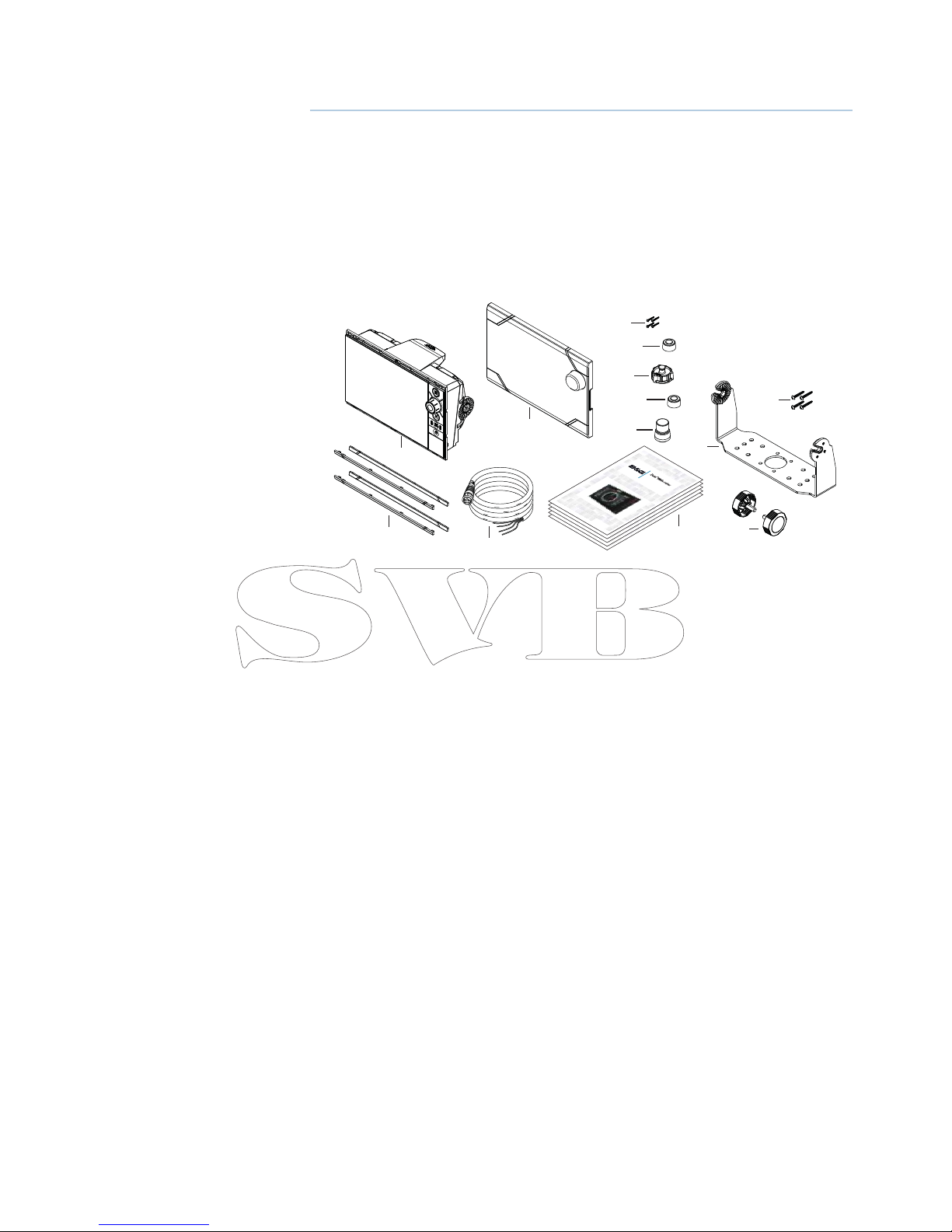
B&G Zeus2 series User manual

ENGLISH
Zeus series
Installation Manual
bandg.com


Preface
As Navico is continuously improving this product, we retain the right to make changes to the
product at any time which may not be reected in this version of the manual. Please contact
your nearest distributor if you require any further assistance.
It is the owner’s sole responsibility to install and use the instrument and transducers in a
manner that will not cause accidents, personal injury or property damage. The user of this
product is solely responsible for observing safe boating practices.
NAVICO HOLDING AS AND ITS SUBSIDIARIES, BRANCHES AND AFFILIATES DISCLAIM ALL
LIABILITY FOR ANY USE OF THIS PRODUCT IN A WAY THAT MAY CAUSE ACCIDENTS, DAMAGE
OR THAT MAY VIOLATE THE LAW.
Governing Language: This statement, any instruction manuals, user guides and other
information relating to the product (Documentation) may be translated to, or has been
translated from, another language (Translation). In the event of any conict between any
Translation of the Documentation, the English language version of the Documentation will be
the ocial version of the Documentation.
This manual represents the product as at the time of printing. Navico Holding AS and its
subsidiaries, branches and aliates reserve the right to make changes to specications
without notice.
Copyright
Copyright © 2014 Navico Holding AS.
Warranty
The warranty card is supplied as a separate document.
In case of any queries, refer to the brand web site of your display or system:
www.bandg.com
Declarations and conformance
This equipment is intended for use in international waters as well as coastal sea areas
administered by countries of the E.U. and E.E.A.
Compliance Statements
The B&G Zeus series;
• complies with CE under R&TTE directive 1999/5/EC
• complies with the requirements of level 2 devices of the Radio-communications
(Electromagnetic Compatibility) standard 2008
The relevant Declaration of Conformity is available on the following website, under the model
documentation section:
www.bandg.com
Warning
The user is cautioned that any changes or modications not expressly approved by
the party responsible for compliance could void the user’s authority to operate the
equipment.
This equipment has been tested and found to comply with the limits for a Class B digital
device, pursuant to Part 15 of the FCC rules. These limits are designed to provide
reasonable protection against harmful interference in a residential installation. This
equipment generates, uses and can radiate radio frequency energy and, if not installed
and used in accordance with the instructions, may cause harmful interference to radio
communications. However, there is no guarantee that the interference will not occur in
a particular installation. If this equipment does cause harmful interference to radio or
television reception, which can be determined by turning the equipment o and on, the

user is encouraged to try to correct the interference by one or more of the following
measures:
Reorient or relocate the receiving antenna
• Increase the separation between the equipment and receiver
• Connect the equipment into an outlet on a circuit dierent from that of the receiver
• Consult the dealer or an experienced technician for help
Trademarks
• NMEA 2000 is a registered trademark of the National Marine Electronics Association
• Navionics is a registered trademark of Navionics SpA
• B&G, Lowrance, StructureScan, Navico, SonicHub, SimNet, Skimmer, InsightHD,
Broadband Radar, Broadband Sonar, and SonarHub are trademarks of Navico, registered
in the US and other countries
About this manual
This manual is a reference guide for installing the B&G Zeus series.
The manual does not cover basic background information about how equipment such as
radars, echosounders and AIS work.
Important text that requires special attention from the reader is emphasized as follows:
Note: Used to draw the reader’s attention to a comment or some important information.
!Warning: Used when it is necessary to warn personnel that they should proceed
carefully to prevent risk of injury and/or damage to equipment/personnel.

Contents
1 Zeus overview
2 Front - controls
3 Rear - connections
4 Hardware installation
4 Display mounting location
5 Display installation
7 Wiring
7 Guidelines
7 Power connection
8 Power Control connection
9 External alarm
10 Connect an external monitor
11 NMEA 2000 – connection to backbone
12 NMEA 0183 device connection
13 Ethernet device connection
13 Video in
14 Software setup
14 First time startup
15 Time and Date
15 Power Control setup
15 Source selection
16 Device list
16 Network Groups
17 Diagnostics
17 External Alarm Setup
17 Radar setup
19 Video In conguration
20 Autopilot setup
26 Fuel setup
28 CZone setup
29 Software updates and data backup
30 NMEA 0183 setup
31 Ethernet setup
32 Wi setup
34 Accessories
35 Supported data
35 NMEA 2000 compliant PGN List
38 NMEA 0183 supported sentences
39 Specications
40 Dimensioned drawings


| 1
Zeus2 overview | Zeus Installation Manual
Zeus overview
The Zeus range of multifunction displays consist of rugged marine displays with built in
powerful marine processors. Display size choices are 7”, 9”, and 12” . All models come with a
built in 10 Hz high gain GPS antenna.
The ability to network over NMEA 2000 and ethernet allows access to data as well as control
of numerous optional devices that can provide radar, audio entertainment, weather and even
digital switching.
All displays can operate on 12 V or 24 V systems.
Each size display may be ush or bracket mounted.
Included Items
1
3
2
11
4
12
13
5
7
8
9
10
6
ENGLISH
Installation Manual
bandg.com
ENGLISH
Installation Manual
bandg.com
ENGLISH
Installation Manual
bandg.com
ENGLISH
Installation Manual
bandg.com
ENGLISH
Installation Manual
bandg.com
1 Zeus display
2 Sun cover
3 Bezels trim (black and silver)
4 Power cable
5 Self tapping pozi screws, 4Gx1/2” (x4 for 7/9, x8 for 12)
6 Ethernet dust cap (x2 for Zeus 12)
7 HDMI dust cap (only for Zeus 12)
8 NMEA 2000 dust cap
9 Video/NMEA 0183 dust cap
10 Document pack (includes: installation manual, user manual, quick start guide,
templates, and warranty card)
11 Bracket
12 Bracket knobs
13 Self tapping pozi screws for bracket

2 | Zeus2 overview | Zeus Installation Manual
Front - controls
8
7
5
3
2
1
4
6
ZEUS 9/12 ZEUS 7
1 Touch screen - cursor control, chart panning and zoom, context related menus
2 Home key - opens home page for page selection and setup options
3 Rotary knob - zooming and menu scrolling / selection by press
4 Exit - exits menu dialogue, clears cursor from screen
5 STBY/AUTO - autopilot control
6 Mark - places waypoint at vessel location
7 Power - turns on unit, opens System Controls dialogue, long press turns o
8 Card reader door - access to dual card reader slot

| 3
Zeus2 overview | Zeus Installation Manual
Rear - connections
5
31 4
54
21 3
1
ZEUS 9/12 ZEUS 7
1 Ethernet - connection to high bandwidth network modules
2 HDMI - video output for external monitor
3 NMEA 2000 - dynamic data and user database sharing
4 Video - input for video sources such as cameras
5 Power - 12 V or 24 V supply input

4 | Hardware installation | Zeus Installation Manual
Hardware installation
Display mounting location
Choose the mounting locations carefully before you drill or cut; The display should be
mounted so that the operator can easily use the controls and clearly see the display screen.
B&G displays are high-contrast and anti-reective, and are viewable in direct sunlight, but for
best results install the display out of direct sunlight. The chosen location should have minimal
glare from windows or bright objects.
If bracket mounting the display, choose an area where the display will not be subjected to
excessive vibration.
The mounting location will aect the internal GPS receiver. Test the unit in it’s intended
location to ensure satisfactory reception. An external GPS source may be added to overcome
poor reception areas.
Leave sucient clearance to connect all relevant cables.
Check that it is possible to route cables to intented mounting location
Ensure that any holes cut are in a safe position and will not weaken the boat’s structure. If in
doubt, consult a qualied boat builder.
Before cutting a hole in a panel, make sure that there are no hidden electrical wires or other
parts behind the panel.
Do not mount any part where it can be used as a hand hold, where it might be submerged, or
where it will interfere with the operation, launching or retrieving of the boat.
Choose an area where the unit will not be subjected to excessive vibration, or heat.
Choose a location that will not expose the unit to conditions that exceed the IP rating - refer
to “Specications” on page 39.
Note: Where ush mounted, the enclosure should be dry and well ventilated. The ventilation
of the space behind the unit should be enough to prevent excessive heat build up as a com-
bined result of radiated heat o the heat sink, and sunlight heating of the enclosure. In very
small enclosures, it may be required to t forced cooling.
!Warning: Inadequate ventilation and subsequent overheating of display may
cause unreliable operation and reduced service life. Ensure enclosure does not con-
sistently exceed +55° C (+131° F) during normal daytime operation (in direct sunlight,
and at full screen brightness).
!Warning: When installing, ensure appropriate safety equipment is used, e.g. ear
mus, protective glasses, gloves and a dust mask. Power tools may exceed safe noise
levels, and can cast o dangerous protectiles. The dust from many materials com-
monly used in boat construction may cause irritation or damage to eyes, skin, and
lungs.

| 5
Hardware installation | Zeus Installation Manual
Display installation
Bracket mounting
Place the bracket in the desired mounting location, and use a pencil or permanent marker to
mark drilling locations.
Note: ensure that the chosen location has enough height to accomodate the display tted in
the bracket, and allows tilting of the display. Also adequate space is required on both sides to
allow tightening and loosening of the knobs.
Use fasteners suited to the mounting surface material. If the material is too thin for self
tappers, reinforce it, or mount bracket with machine screws and large washers. Use only 304
or 316 stainless steel fasteners. Mark the screw locations using bracket as template, and drill
pilot holes.
Screw down the bracket.
Mount the display to the bracket using the knobs. Hand tighten only. The ratchet teeth in
the bracket and display case ensure a positive grip and prevent the unit changing from the
desired angle.

6 | Hardware installation | Zeus Installation Manual
Flush mounting
Check the template for scaling accuracy, using a tape
measure or ruler against the ruler printed on the
template.
Cut away excess paper if required, and tape template
to mounting surface. Check it is correctly aligned to a
vertical or horizontal reference. Do not use a bubble
level as vessel may be listing! Adjust where required.
Drill all marked pilot holes, then using an appropriate
saw, cut through the template and mounting surface,
along the dotted line bordering the shaded area of the
template.
Check the t of the display, and le away
remaining obstructions. Secure the display
with the supplied screws. Once screws are fully
tightened, ensure there is complete contact
with the mounting surface.
Bezel Fitment and Removal
When tting bezels, ensure hook tabs on
back of each bezel recess in to opposing
slots on screen frame. Once ush with front
surface of screen, slide top bezel to the left,
and bottom bezel to the right to lock in to
place. The bezel trim have been designed
to be very low prole, and therefore fully
conceal the locking tabs that keep them
from being accidentally disengaged from
the mounting ange. To release the locking
tab, it is necessary to gently lever the centre
of the bezel trim away from the mounting
ange. To remove the cover, simultaneously
slide it sideways; to the right for the top
bezel, and to the left for the bottom bezel.
REMOVESHADEDAREA
*988-10455-001*
NOTE:
DONOT SCALE
PRINT1:1
IMPORTANT.Donotusethis template if ithas beenrescaled
bycopyingor prin ng.Ifthisis not the original, oris a print
fromale, please check the dimension lines below are to
scalebeforeuse.
IMPORTANT.Nepasu liser ce gabarit s’il a été photocopiéou
impriméenformat réduit ou agrandi. Si ce gabarit n’estni un
originalniuneversion impriméed’un chier PDF,veuillez
vérierqu’ilestà l’échelle avant de l’uliser.
IMPORTANTE.nousarla plan llasihay peligroque la escala
originalexactaseha alterado por copias o procesos de
impresiónimprecisos.Siesto no es el original, o un PDF,veri
carquelaslíneasabajo están a la escala antes de usar.
WICHTIG.DiesenVordrucknichtverwenden, wenn er durch
KopierenoderDrucken im Maßstab verändert wurde.Sollte
esnichtdas Originaloder ein PDF-Ausdruck sein, müssen
untenstehendeZeilenvorerwendungan den rich gen
Maßstabangepasstwerden.
BELANGRIJK.Gebruikdeze malnietindiende schaal is veran-
derddoordathetisgecopieerd ofgedrukt.Indien dezemal
niethetorigineelofeenprintvanPDFis, controleer danofde
onderstaandelijnendejuisteschaal zijnvoordatuzegebrui-
kt.
IMPORTANTE.Nãou lizeestegabaritosea escala do mesmo
versidoalteradaporcópia ou impressão. Se não foro
originalouumacópia impressadeumarquivoPDF,verique
aslinhasabaixo,para acertara escala antes da u lização.
VIKTIGT.Användintedennamallom den skalats omgenom
utskri ellerkopiering.Omdeainte är originalet eller en
utskri frånenPDF,kontrolleraalinjerna nedan stämmer
medskalaninnandetanvänds.
IMPORTANTE.Nonu lizzare questomodello se èstato
ridimensionatocopiandoloostampandolo.Sequesto nonè
l’originaleolastampa diun le PDF,vericarese le linee che
seguonodevonoesseredimensionate prima di essereulizza-
te.
TÄRKEÄÄ.Äläkäytätätäkaaviota,jos sen mi akaava on
muuunutkopio-idessataitulostaessa.Jos tämä ei olealku-
peräinentaiPDF tuloste tarkista rajatmiakaavastaalla
ennenkäyöä.
⊼ᛣ˖䇋ሑ䞣ϡ㽕Փ⫼ᴀᅝ㺙ᣪᄨሎᇌ⠜ⱘӊDŽ
བᵰՓ⫼ӊˈ߭Փ⫼Пࠡ䇋⹂䅸݊↨՟ϔᅮ㽕Ϣ
ӊᇣᖙ乏ϔ㟈DŽ
㩅㟈aG⸩㇠⇌G㻐⥙㡰⦐G䆠ὤᴴG㦤㥉G═G㟤G㢨G䊐䙀⫳㡸G
㇠㟝䚌㫴G⫼㐡㐐㝘UG㠄⸬㢨G㙸⏼ᶤ⇌G㢬㋸Ɒ㢨⮨SG
㇠㟝䚌ὤG㤸G㙸⣌G㾌㍌㉔㢌G⌼Ἴ㡸G䞉㢬G䚨G㨰㐡㐐㝘U
謗ஔအြ႒ႿႣႸー႔ွ襙蕧ၒၿႠー္ၖေဴ貽谞ယ変
ၝေဴဒၙအံယတၘ၌ဧြဵ萦蠯ဥးဒဵ踆ဣဒଟ႒
ႿႣႸー႔ယၶႶႄ႖Ⴗြၐြဵးဒ见踵္ွଞ踆ြ貎
茽蓧ၠ萦ေဴ貽谞ၠ輑襨ဥဴဝီဣဒଟ
ɩɴɯɳɧɴɯɬaGɴʌGʏʘʖʕʒʣʎʚʐʙʌGʤʙʚGʏʔʘʙʗʚʑʝʏʥSGʌʘ
ʒʏGʕʔʇGʈʢʒʇGʏʎʓʌʔʌʔʇGʉGʗʇʎʓʌʗʇʜGʖʗʏGʑʕʖʏʗʕʉʇ
ʔʏʏGʏʒʏGʗʇʘʖʌʞʇʙʑʌUGɬʘʒʏGʉʢGʏʘʖʕʒʣʎʚʌʙʌGʔʌGʕʗ
ʏʊʏʔʇʒSGʇGʗʇʘʖʌʞʇʙʑʚGʏʎGʛʇʐʒʇSGʚʈʌʋʏʙʌʘʣGʉGʘʕʕ
ʙʉʌʙʘʙʉʏʏGʗʇʎʓʌʗʕʉGʒʏʔʌʐʑʏGʉGʔʏʍʔʌʐGʞʇʘʙʏGʏ
ʔʘʙʗʚʑʝʏʏGʘGʋʌʐʘʙʉʏʙʌʒʣʔʢʓʏGʗʇʎʓʌʗʇʓʏU
Checkdimensions before cutting
12"
300mm
L
C
L
C
192.5mm (7.58")
186.0mm (7.32")
192.5mm(7.58")
186.0mm (7.32")
200.0mm(7.87")
117.5mm (4.63")
111.0mm (4.37")
130.0mm (5.12")130.0mm (5.12")
117.5mm (4.63")
111.0mm (4.37")
200.0mm (7.87")
385.0mm (15.16")
372.0mm (14.65")
400.0mm (15.75")
235.0mm (9.25")
222.0mm (8.74")
260.0mm (10.24")
MO16
Marine Monitor
X4
1
3
x4
x2
4
CLICK
5
6
7
2

| 7
Wiring | Zeus Installation Manual
Wiring
Guidelines
Care must be taken when running cables in a boat, to ensure that the cables are protected
from damage and do not interfer with mechanical systems such as throttle cables and hatch
covers.
At each end of a cable, it is advisable to leave a short loop hanging lower than the termination
point. This prevents any water that may get in contact with the cable from running down it to
termination points vulnerable to corrosion.
Extending cables should be done with suitable crimp connectors or solder and heat shrink.
Keeps joins as high as possible to minimize possibility of water immersion.
Routing cables adjacent to high current or high frequency signal cables could cause noise to
be induced from one device to another. Allow spacing between cables where possible.
Secure all cables at regular intervals, to prevent movement during boat operation. Cable
movement may cause fatigue at termination points or cause the cable to interfere with other
boat systems.
Allows enough cable slack for easy access to connectors when removing the device from a
bracket or ush mount installation.
!Warning: Before starting the installation, be sure to turn electrical power o. If
power is left on or turned on during the installation, re, electrical shock, or other
serious injury may occur. Be sure that the voltage of the power supply is compatible
with the Zeus2 display
!Warning: The positive supply wire (red) should always be connected to (+) DC with
the supplied fuse or a circuit breaker (closest available to fuse rating).
Power connection
Zeus displays are designed to be powered by a 12 or 24 V DC system. They are protected
against reverse polarity, under voltage and over voltage.
+_
2
34
6
7
5
1
1 Zeus display
2 Four pin power cable
3 Positive supply, 12/24V (red wire)
4 Negative (black wire)
5 Power control (yellow wire)
6 Alarm output (blue wire)

8 | Wiring | Zeus Installation Manual
Power Control connection
The yellow Power Control wire on the Zeus power cable can either be an input that will turn
on the processor when power is applied, or an output that turns on other devices when the
processor is powered on. It can be congured at the installation stage to control the power
state of displays and compatible devices. When commissioning the system, the Zeus can be
set to be a Power Control Slave or Power Control Master.
Power Control conguration options of the Zeus are:-
• Zeus to turn on when power key pressed: Yellow wire not connected
• Zeus to turn on when power source is turned on: Common red and yellow wires
• Zeus to turn on with power key, as well as other compatible devices such as Broadband
Radar: Yellow wire connected to a Power Control Bus. (Set one or more displays to be a Power
Control Master)
Power Control unconnected
Device will turn on and o when the power
button on the front of the unit is pressed.
Leave yellow Power Control wire disconnected.
Tape or heat-shrink end to prevent shorting.
Power Control to supply positive (auto on)
Device will turn on immediately when power is
applied. Common the yellow wire with the red
wire after the fuse.
Note: The unit can not be powered down by
power button, but can be put in to standby
mode. (screen backlight also turns o).
+_
+_

| 9
Wiring | Zeus Installation Manual
Power Control master/slave bus
Turning on the ‘master’device turns on connected ‘slave’devices.
1 Zeus displays
2 Power cable
3 Radar Interface box
4 Sonic Hub
5 Ground wire
6 Positive wire
7 Power control wire
If the left Zeus turns on using the power button and is set as the Power Control Master, it will
output voltage on the Power Control bus to power on the other Zeus, the Radar Interface,
and the SonicHub.
If the right Zeus is set to Power Control Slave, it cannot be powered down using its own
power button, but can be set to standby.
If the left Zeus (Power Control Master) is o, the right Zeus can be turned on using its own
power button, but won’t turn on any other devices.
To turn on all network devices from either Zeus, both devices can be congured as Power
Control Masters.
Note: If an Zeus has its power state controlled by another device (or ignition switch), it can’t
be totally powered down. It can however enter a standby state to save power. If the power
button is pressed and Power O selected, a message will appear “Preparing to standby…”
External alarm
Blue wire on power cable:
An external alarm can be connected to one or more Zeus displays on the network. The
external alarm can be a small peizo buzzer connected directly, or a horn siren connected via a
relay.
Alarms are congured globally in the system i.e they can be congured on any one
networked multifunction device or Triton instrument, and be seen, heard, and acknowledged
from all devices. Individual devices can also be congured to not to sound their internal
buzzer, but still display the alarm information. For information on conguring alarms, refer to
the Alarms section in the Operator manual.
+_
6
3
2
7
8
5
4
1

10 | Wiring | Zeus Installation Manual
+_
For sirens that draw more than 1 Amp, use a relay
+_
Connect an external monitor
The Zeus 12 oers an HDMI output which can be connected to an external monitor to
replicate video at a remote location.
13
2
4
1 MO series monitor
2 HDMI cable
3 Zeus 12
4 HDMI cable - waterproof connector (use in exposed installations)
Note: If connected to an HDTV it is possible the image may appear cropped, ie missing some
detail at the outer edges of the screen. This is usually due to overscan applied by the TV. Refer
to your TV operator manual to nd if and how overscan can be turned o.

| 11
Wiring | Zeus Installation Manual
NMEA 2000 – connection to backbone
Device connection
The Zeus multi function displays are equiped with an NMEA 2000 data port, which allows the
receiving and sharing of a multitude of data from various sources.
Essential network information
• The standardised physical cables/connectors for NMEA 2000 are ‘Micro-C’ and ‘Mini-C’,
directly derived from the automation industy’s ‘DeviceNET’ - ‘Micro-C’ being the more
commonly used size.
• A network consists of a linear ‘backbone’ from which ‘drop cables’ connect to NMEA 2000
compliant devices
• A single drop cable has a maximum length of 6 m (20 ft). The total length of all drop cables
combined should not exceed 78m (256 ft)
• A NMEA 2000 network, using Micro-C cabling, has a maximum cable length of 100 m (328 ft),
between any two points
• A NMEA 2000 network needs to have a terminator at each end of the backbone. A terminator
can be one of the following:
• a terminator blank plug
• a wind transducer (where the mast cable is one end of the backbone)
Planning and installing a network backbone
The Micro-C backbone needs to run between the locations of all products to be installed -
typically in a bow to stern layout - and be no further than 6 m from a device to be connected.
Choose from the following components to make up the backbone:
• Micro-C cables: 0.6 m (2 ft), 1.8 m (6 ft), 4.55 m (15 ft), and 7.58 m (25 ft) cables
• T-connector. Used to connect a drop cable to the backbone
• Micro-C power cables. Connected to backbone via a T-connector
Note: When using a wind sensor, the mast cable should be connected at one end of the
backbone, as the sensor is tted with a termination resistor.
Note: Most NMEA 2000 devices can be connected directly to a SimNet backbone and SimNet
devices can be connected to a NMEA 2000 network by using adapter cables.
Note: B&G devices are fully compatible with a SimNet network by using a Micro-C to SimNet
adapter cable.
Note: Triton displays have two Micro-C connectors, and can either be connected inline with
the backbone, or wired individually o a drop cable. Connecting from device to device is
known as ‘daisy chaining’ This network topology is not ocially NMEA 2000 compliant.
Power the network
The network requires its own 12 V DC power supply protected by a 5 amp fuse or breaker. For
vessels tted with 24 V systems, use a DC-DC converter to supply 12 V.
Connect power at any location in the backbone for smaller systems.
For larger systems introduce power at central point in the backbone to “balance” the voltage
drop of the network.
Note: If joining to an existing NMEA 2000 network that already has its own power supply, do
not make another power connection elsewhere in the network, and ensure existing network
is not powered by 24 V DC.
Note: Do not connect the NMEA 2000 power cable to the same terminals as the engine start
batteries, autopilot computer, radar, bow thruster or other high current devices.

12 | Wiring | Zeus Installation Manual
The following drawing demonstrates a typical small network. The backbone is made up of
direcly interconnected T-piece joiners and an extension cable, which is terminated at each
end.
+
_
12 V DC TT
9
8
5
7
6
4
3
2
1
9
1 GPS antenna
2 Zeus
3 Broadband radar interface
4 SonicHub
5 ‘Drop’ cables (should not exceed 6m (20’) each)
6 Power cable
7 Micro-C T junctions
8 Backbone
9 Micro-C terminator (one male, one female)
NMEA 0183 device connection
The Zeus display has an NMEA 0183 serial port, providing both an input and an output.
The port uses the NMEA 0183 (serial balanced) standard, and can be congured in the
software for dierent baud rates up to 38,400 baud.
1 NMEA 0183 RX_B (orange)
2 NMEA 0183 RX_A (green)
3 NMEA 0183 TX_B (blue)
4 NMEA 0183 TX_A (yellow)
Note: The connector for NMEA 0183 is labelled VIDEO, as the cable is dual purpose and carries
both composite video and NMEA 0183 (on seperate wires).
Talkers and Listeners
Do not connect multiple devices outputing data (Talkers) on to the serial input (Rx) of the
unit. The NMEA 0183/RS422 standard is not intended for this type of connection, and data
will be corrupted if multiple devices transmit simultaneously. The output however may drive
A
B
+
+
-
-
RX_B
RX_A
TX_B
TX_A
12
34

| 13
Wiring | Zeus Installation Manual
multiple receivers (Listeners). The number of receivers is nite, and depends largely on the
receiving hardware. Typically driving three devices is possible.
Ethernet device connection
Ethernet is used to interconnect high bandwidth devices such as radar, sonar, and other
multi function displays. The Zeus 7/9 have one ethernet port, whereas the Zeus 12 has two.
Connection of network devices can be made directly, or via a NEP-2 ethernet expansion port.
Additional NEP-2s can be added to provide required number of ports.
Note: some ethernet devices are equiped with two or more ethernet ports, which allow con-
nection of additional devices, and may eliminate the need for an extra NEP-2.
Video in
Each Zeus can be connected to two composite video cameras, and display video images on
its displays. Both NTSC and PAL formats are supported. The Zeus video input cable is tted
with female RCA plugs - the camera cables should be terminated with male RCA cables to
suit.
VIDEO 1
VIDEO 2
RED
GREEN
Note: The video images will not be shared with another unit via the network. It is only pos-
sible to view video on the unit connected to the video source.

14 | Software setup | Zeus Installation Manual
Software setup
The Zeus requires some initial conguration before use, in order to get the most out of the
product.
The following sections focus on settings that typically will not require change once
congured. User preference settings and operation are covered in the operator manual.
Pressing the home key brings up the home page, which has three distinct panels.
The scrollable left column of icons access most settings that require conguration;
First time startup
When the Zeus is started for the rst time, or after a factory default, the unit will raise
prompts requesting the user to select some fundamental setup options;
Choose language.
Initiate source selection for data sources both internal and external to device.
Check all external data sources and NMEA 2000 data bus are turned on.
Simulation uses recorded data to allow product demonstration of features otherwise not
possible without physical installation on a vessel.
Other manuals for Zeus2 series
4
This manual suits for next models
3
Table of contents
Other B&G Marine Equipment manuals

B&G
B&G Network Series User manual

B&G
B&G Zeus3 Glass Helm User manual

B&G
B&G Network Series User manual

B&G
B&G H5000 Pilot Use and care manual

B&G
B&G PTT User manual

B&G
B&G RAM T3 User manual

B&G
B&G Triton Display User manual

B&G
B&G Zeus Touch User manual

B&G
B&G HB-1000I User manual

B&G
B&G Zeus3 Glass Helm User manual