Marine Air Systems vector compact Installation and operating instructions

vector
compact
INSTALLATION,
OPERATION
&
MAINTENANCE
/HARINE
/IIR
SYSTEMS®
A
Member
of
Taylor
Made
Group.
6/99
Patented

PREFACE
Congratulations
on
the
purchase
of your
Marine
Air
Systems
VECTOR
COMPACT
air
conditioner.
No
matter
which
of
the
following
features
was
the
reason
for
your
purchase
of
this
air
conditioner,
we
are
sure
it
will
meet
your
needs
and
will
give
you
many
years
of
efficient
and
trouble
free use.
The
VECTOR
COMPACT
units
are
self-contained
direct
expansion
air
conditioners
designed
for
marine
applications
incorporating
the
following
features:
•
Patented
compact
design
with
the
condenser
coil
in
the
evaporator
shroud.
•
High
efficiency
rotary
(7-16K)
or
scroll
(24K)
compressors
•
Cupronickel
condenser
coil
•
Raised
lance
fin
designed
evaporator
coil
•
Polyurethane
coated
2"
deep
drain
pan
with
multiple
condensate
drain
locations
•
Anti-vibration
base
pan
•
Pre-charged
and
pre-wired
systems
for
easy
connections
•
Rotatable
insulated
blower
assembly
•
Charge
Guard®
ensures
environmental
protection
and
system
integrity
The
PASSPORT
II
microprocessor
based
digital
controller,
optional
with
this
unit,
offers
the
most
technologically
advanced
design
specifically
made
for
the
unique
requirements
of
marine
air
conditioning.
The
controller
has
been
designed
with
flexibility
and
the
following
"user
friendly"
features
customers
require
for
their
applications:
•
Non-volatile
memory
•
Program
lock
-
prevents
accidental
program
tampering
•
Low
voltage
display
panel
•
Face
plate
air
sensor
for
accurate
temperature
control,
or
optional
remote
sensor
•
LED
cabin
temperature
displayed
in
Fahrenheit
or
Celsius
•
Multiple
fan
speed
selections
with
high
and
low
limits
•
User
selected
programs
for
optimum
control
•
Optional
outside
air
temperature
sensor
•
Compressor
pressure
failsafe
protection
and
run
time
hour
meter
•
Compressor
start
staging
delay
for
multiple
a/c
systems
•
Moisture
mode
cycle
for
humidity
control
•
De-icing
feature
to
prevent
evaporator
icing
•
Blank
display
for
nighttime
operation
This
manual
is
intended
to
provide
the
information
necessary
to
ensure
proper
installation,
operation,
and
maintenance
of
the
unit.
Improper
installation
or
misunderstood
operating
procedures
can
result
in
unsatisfactory
performance
and/or
premature
failure
of
these
units,
so
before
proceeding
please
read
this
manual
completely.
The
VECTOR
COMPACT
a/c
units
are
covered
under
the
existing
Marine
Air
Systems'
warranty
policy
contained
in
this
manual.
In
the
interest
of
product
improvement,
Marine
Air
Systems'
specifications
and
design
are
subject
to
change
without
prior
notice.
REVISION
HISTORY
DOCUMENT
NAME:
Vector
Compact.doc
ORIGINAL
PRINT:
March
1998
REVISED:
5/98,
7/98
&
11/98

CLEAN
AIR
ACT
AMENDMENTS
OF
1990
[TITLE
VI
-
SECTION
608(C-1)]
"Effective
July
1,
1992,
it
shall
be
unlawful
for
any
person,
in
the
course
of
maintaining,
servicing,
repairing,
or
disposing
of an
appliance
or
industrial
process
refrigeration,
to
knowingly
vent
or
otherwise
knowingly
release
or
dispose
of
any
Class
I*
or
Class
II**
substance
used
as
a
refrigerant
in
such
appliance
(or
industrial
process
refrigeration)
in
a
manner
which
permits
such
substance
to
enter
the
environment.
De
minimis
releases
associated
with
good
faith
attempts
to
recapture
and
recycle
or
safely
dispose
of
any
such
substances
shall
not
be
subject
to
the
prohibition
set
forth
in
the
proceeding
sentence."
*Class
I
substances
include
CFC-12
**Class
II
substances
include
HCFC-22
MARINE
AIR
SYSTEMS
Marine
Air
Systems,
Inc.
(MAS)
is
a
manufacturer
of
air
conditioning
and
refrigeration
equipment
for
the
marine
industry.
MAS
is
committed
to
innovative
technology,
competitively
priced
products
and
market
leadership.
The
MAS
team
has
many
years
of
experience
in
the
design,
manufacture,
application
and
support
of
marine
air
conditioning
and
refrigeration.
Our
practical
experience
and
design
capability
allows
our
application
engineers
and
customer
support
team
to
offer
optimum
solutions
for
your
environmental
control
requirements.
Marine
Air
Systems,
Inc.
is
A
Member
of
the
Taylor
Made
GroupT
'TM*
VECTOR
COMPACT
OVERVIEW
ROTATABLE
BLOWER
BLOWER
MOTOR
CONDENSER
COIL
OUTLET
CONDENSER
COIL
INLET
ROTARY
COMPRESSOR
EVAPORATOR
COIL
SHROUD
WITH
CONDENSER
COIL
INSIDE
ELECTRIC
BOX
REVERSING
VALVE
BASE/DRAIN PAN
HANDLE
HOW
IT
WORKS:
Your
self-contained
air
conditioner
consists
of
four
main
components
and
a
refrigerant
gas
circulating
through
the
system.
The
BLOWER
draws
warm
moist
cabin
air
across
the
fins
on
the
EVAPORATOR
where
the
heat
from
the
air
causes
the
refrigerant
in
the
evaporator
coil
to
evaporate
from
a
liquid
into
a
gas.
As
the
refrigerant
evaporates,
it
absorbs
the
heat
from
the
cabin
air.
The
moisture
in
the
air
is
captured
on
the
evaporator
coil
and
fins
by
forming
condensation
as
the
air
is
cooled.
The
COMPRESSOR
then
compresses
the
refrigerant
gas
and
pumps
it
through
the
outer
tube
in
the
CONDENSER
COIL
(located
in
the
evaporator
shroud).
The
seawater
pump
circulates
cool
seawater
through
the
inner
tube
in
the
condenser
coil;
this
cools
the
refrigerant
and
condenses
it
into
a
liquid.
The
heat
from
the
refrigerant
is
exchanged
to
the
seawater
and
discharged
overboard.
The
liquid
refrigerant
is
then
passed
through
the
EVAPORATOR
COIL
and
the
cycle
repeats.
Removing
heat
and
moisture
from
the
cabin
air
lowers
its
temperature
and
humidity
levels.
The
conditioned
air
is
blown
through
the
ducting
and
out
the
supply
air
grille(s).
For
reverse
cycle
heating,
the
refrigerant
flows
in
the
opposite
direction
through
the
reversing
valve.
Heat
is
transferred
from
the
seawater
in
the
condenser
coil
to
the
refrigerant
and
then
to
the
air
blowing
through
the
evaporator
into
the
cabin.
Seawater
temperature
will
directly
affect
the
a/c unit's
efficiency.
This
a/c
unit
can
effectively
cool
your
boat
in
water
temperatures
up
to
90°F
and
heat
it
in
water
temperatures
as
low
as
40°F.
n

TABLE
OF
CONTENTS
INSTALLATION
Unpacking
and
Inspection
1
Safety
Considerations
1
Placement
of
System
(Tools
Required)
2
Spacing
Allowances
and
Dimensions
3
Condensate
Drains
4
Mounting
Brackets
4
Blower
Assembly
4
Supply
&
Return
Air
Grilles
5
Ducting
5
Seawater
Pump
and
Plumbing
6
Electrical
Connections,
Grounding
and
Bonding
7
3
Phase
Notice
7
Vector
Compact
Mechanical
Control
(VCM)
Wiring
Diagrams
8
Vector
Compact
Passport
II
Digital
Control
(VCP)
Wiring
Diagrams
.9
Manual
Control
Panel
(MCP)
Installation
10
Passport
II
Display
Panel
Installation
11
Installation
Checklist
(review
prior
to
installation)
12
OPERATION
Manual
Control
Panel
(MCP)
Operation
10
Quick
Start
Operations
Checklist
12
Passport
II
Control
13
Modes
of
Operation
13-14
Programming
the
Passport
II
14-15
Programmable
Parameters
15-17
Programming
Notes
17
General
Troubleshooting
Guidelines
18-19
Passport
II
Digital
Control
Troubleshooting
Guidelines
19-21
MCP
Mechanical
Control
Panel
Troubleshooting
Guidelines
....21
MAINTENANCE
Seawater
System,
Return
Air
Filters,
Winterization
22
Manufacturers
Limited
Warranty
Agreement
23
Worldwide
Dealer/Service
Network
1998
24-25
in

UNPACKING
AND
INSPECTION
When
the
equipment
is
received,
all
items
should
be
carefully
checked
against
the
packing
list
to
ensure
all
cartons
have been
received.
Move
units in
the
normal
"up"
orientation
as
indicated
by
the
arrows
on
each
carton.
Examine
cartons
for
shipping
damage,
removing
the
units
from
the
cartons
if
necessary.
If
the
unit
is
damaged,
the
carrier
should
make
the
proper
notation
on
the
delivery
receipt
acknowledging
the
damage.
SAFETY
CONSIDERATIONS
VERY
IMPORTANT:
A/ever
install
your
air
conditioner
in
the
bilge
or
engine
room
areas.
Insure
that
the
selected
location
is
sealed
from
direct
access
to
bilge
and/or
engine
room
vapors.
Do
not
terminate
condensate
drain
line
within
four
(4)
feet
of
any
outlet
of
engine
or
generator
exhaust
systems,
nor
in
a
compartment
housing
an
engine or
generator,
nor
in
a
bilge,
unless
the
drain
is
connected
properly
to
a
sealed
condensate
or
shower
sump
pump.
Installation
and
servicing
of
this
system
can
be
hazardous
due
to
system
pressure
and
electrical
components.
When
working
on
this
equipment,
always
observe
precautions
described
in
the
literature,
tags
and
labels
attached
to
the
unit.
Follow
all
safety
codes.
Wear
safety
glasses
and
work
gloves
and
place
a
fire
extinguisher
close
to
the
work
area.
The
following
is
a
summary
of
the
labels
on
the
unit:
!
DANGER
ELECTRICAL
SHOCK
HAZARD.
DISCONNECT
VOLTAGE
AT
MAIN
PANEL
OR
POWER
SOURCE
BEFORE
OPENING
ANY
COVER.
FAILURE
TO
COMPLY
MAY
RESULT
IN
INJURY
OR
DEATH.
!
WARNING
THIS
COMPONENT
DOES
NOT
MEET
FEDERAL
REQUIREMENTS FOR
IGNITION
PROTECTION.
DO
NOT
INSTALL
IN
SPACES
CONTAINING
GASOLINE
ENGINES,
TANKS,
LPG/CPG
CYLINDERS,
REGULATORS,
VALVES
OR
FUEL
LINE
FITTINGS.
FAILURE
TO
COMPLY
MAY
RESULT
IN
INJURY
OR
DEATH
NOTICE
THIS
COMPONENT
IS
CHARGED
WITH
HYDROCHLOROFLUOROCARBON
(HCFC)
REFRIGERANT
R22.
EFFECTIVE
JULY
1,
1992
IT
SHALL
BE
UNLAWFUL
FOR
ANY
PERSON
TO
KNOWINGLY
VENT
OR
OTHERWISE
KNOWINGLY
RELEASE
ANY
CLASS
1
(CFC)
OR
CLASS
2
(HCFC)
SUBSTANCE
AS
A
REFRIGERANT
IN
A
MANNER
WHICH
PERMITS
SUCH
SUBSTANCE
TO
ENTER
THE
ATMOSPHERE
PER
THE
CLEAN
AIR
ACT
OF
1990.
PUBLIC
LAW
101-549
TITLE
IV
SECTION
608-C.
FAILURE
TO
COMPLY
MAY
RESULT
IN
SEVERE
PENALTIES,
INCLUDING
FINES
AND
IMPRISONMENT.
!
WARNING
TO
MINIMIZE
THE HAZARD
OF
ELECTRICAL
SHOCK
AND
PERSONAL
INJURY,
THIS
COMPONENT
MUST
BE
EFFECTIVELY
GROUNDED.
REFER
TO
THE
INSTALLATION
GUIDELINES
FOR
FURTHER
INFORMATION.
CAUTION!
HIGH
COMPRESSOR
TEMPERATURE
IS
NORMAL
DO
NOT
TOUCH
PLACEMENT
OF SYSTEM
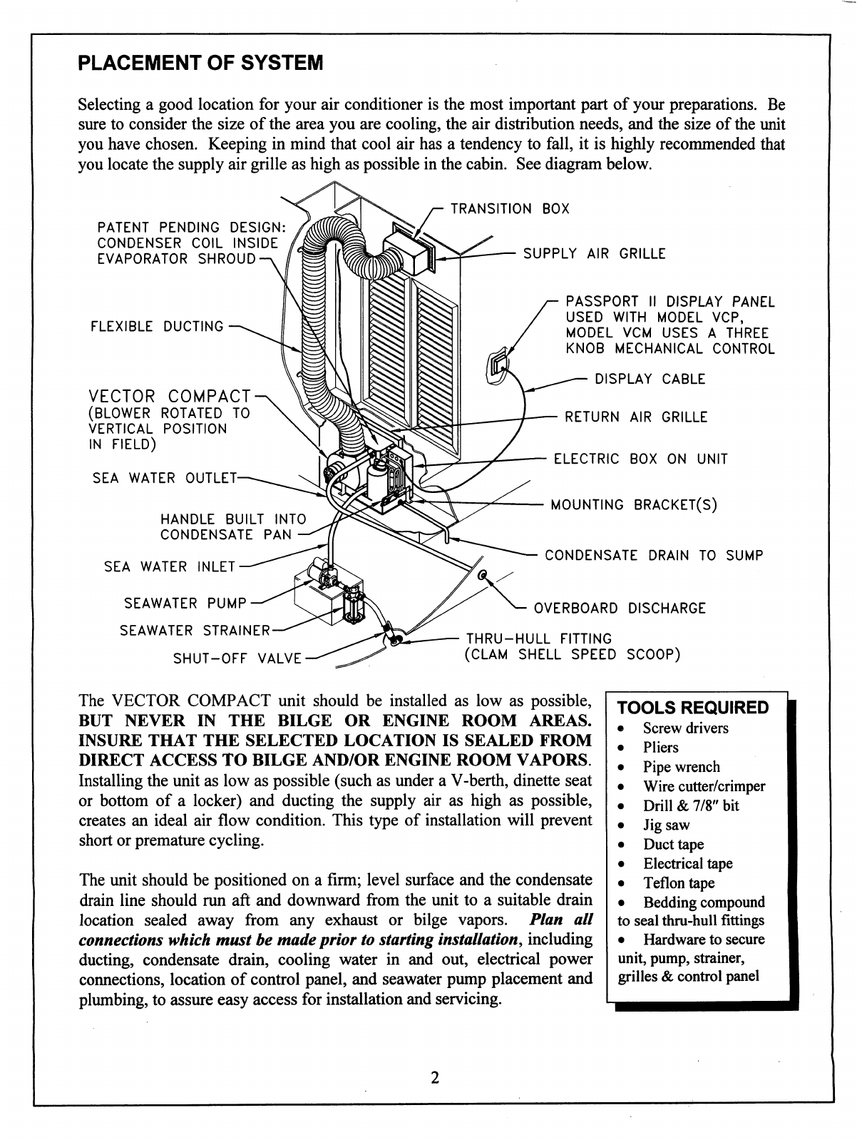
Selecting
a
good
location
for
your
air
conditioner
is
the
most
important
part
of
your
preparations.
Be
sure
to
consider
the
size
of
the
area
you
are
cooling,
the
air
distribution
needs,
and
the
size
of
the
unit
you
have
chosen.
Keeping
in
mind
that
cool
air
has a
tendency
to
fall,
it
is
highly
recommended
that
you
locate
the
supply
air
grille
as
high
as
possible
in
the
cabin.
See
diagram
below.
TRANSITION
BOX
PATENT
PENDING
DESIGN:
CONDENSER
COIL
INSIDE
EVAPORATOR
SHROUD
FLEXIBLE
DUCTING
VECTOR
COMPACT
(BLOWER
ROTATED
TO
VERTICAL
POSITION
IN
FIELD)
SEA
WATER
OUTLET-
HANDLE
BUILT
INTO
CONDENSATE
PAN
SEA
WATER
INLET
SEAWATER
PUMP
SEAWATER
STRAINER
SHUT-OFF
VALVE
SUPPLY
AIR
GRILLE
PASSPORT
II
DISPLAY
PANEL
USED
WITH
MODEL
VCP,
MODEL
VCM
USES
A
THREE
KNOB
MECHANICAL
CONTROL
DISPLAY
CABLE
RETURN
AIR
GRILLE
ELECTRIC
BOX
ON
UNIT
MOUNTING
BRACKET(S)
CONDENSATE
DRAIN
TO
SUMP
OVERBOARD
DISCHARGE
THRU-HULL
FITTING
(CLAM
SHELL
SPEED
SCOOP)
The
VECTOR
COMPACT
unit
should
be
installed
as
low
as
possible,
BUT
NEVER
IN
THE
BILGE
OR
ENGINE
ROOM
AREAS.
INSURE
THAT
THE
SELECTED
LOCATION
IS
SEALED
FROM
DIRECT
ACCESS
TO
BILGE
AND/OR
ENGINE
ROOM
VAPORS.
Installing
the
unit
as
low
as
possible
(such
as
under
a
V-berth,
dinette
seat
or
bottom
of
a
locker)
and
ducting
the
supply
air
as
high
as
possible,
creates
an
ideal
air
flow
condition.
This
type
of
installation
will
prevent
short
or
premature
cycling.
The
unit
should
be
positioned
on
a
firm;
level
surface
and
the
condensate
drain
line
should
run
aft
and
downward
from
the
unit
to
a
suitable
drain
location
sealed
away
from
any
exhaust
or
bilge
vapors.
Plan
all
connections
which
must
be
made
prior
to
starting
installation,
including
ducting,
condensate
drain,
cooling
water
in
and
out,
electrical
power
connections,
location
of
control
panel,
and
seawater
pump
placement
and
plumbing,
to
assure
easy
access
for
installation
and
servicing.
TOOLS
REQUIRED
•
Screw
drivers
•
Pliers
•
Pipe
wrench
•
Wire
cutter/crimper
•
Drill
&
7/8"
bit
•
Jig
saw
•
Duct
tape
•
Electrical
tape
•
Teflon
tape
•
Bedding
compound
to
seal
thru-hull
fittings
•
Hardware
to
secure
unit,
pump,
strainer,
grilles
&
control
panel

PROPRIETARY
NOTE:
THE
INFORMATION
CONTAINED
WITHIN
THIS
DOCUMENT
IS
THE
PROPERTY
OF
MARINE
AIR
SYSTEMS
INC.
ANY
ATTEMPT
TO
COPY
OR
DISTRIBUTE
WITHOUT
WRITTEN
CONSENT
FROM
MARINE
AIR
SYSTEMS
INC.
SHALL
BE
CONSIDERED
UNLAWFUL
AND
CAN
BE
CONTESTED
IN
A
COURT
OF
LAW.
REV
1
J
K
L
DATE
N/A
4/16/98
1/13/99
5/10/99
REVISION
NO
REVISION
'I'
REVISED
DIMENSIONS
ON
10
&
12
HV
UNITS
CHANGED
24K
M
DIMENSION
ADDED
5K
UNIT
DWG
DKM
DKM
DKM
DKM
APR
R
P
D
D
SPACE
ALLOWANCES
TO
CONSIDER
WHEN
DESIGNING
AREA
FOR
A/C
UNITS
1)
Allow
a
minimum
3.00"
[7.62cm]
of
air
space
in
front
of
evaporator
for
return
air
intake
if it
is
adjacent
to
a
bulkhead.
2)
Allow
a
minimum
1.00"
[2.54cm]
of
air
space
for
electric
blower
motor
ventilation.
Not
applicable
with
HV
units.
3)
For
flexible
ducting
connection:
A)
If
mount
ring
is
used,
allow
2.00"
[5.08cm]
for
the
ring,
1.00"
[2.54cm]
for
duct
bend
radius
and
add
the
diameter
of
the
ducting
to
get
total
distance
as
measured
from
blower
outlet.
B)
When
using
a
transition
box
consider
thot
each
box
is
unique
to
it's
application.
A
general
rule
is
to
add
1.00"
[2.54cm]
to
the
largest
ring
diameter
used
to
get
size
of
box
(5"
min.).
Add
mount
ring
and
ducting
as
figured
above
to
get
approximate
space
needed
to
install
transition
box.
Also
note
that
the
universal
T-box
is
8.00"
[20.32cm]
tall
measured
from
blower
outlet.
4)
Allow
enough
room
for
removal
of
electric
box
cover
for
servicing.
NOTE:
The
above
dimensions
are
minimums.
Enough
space
should
be
allocated
for
installation
and
serviceability.
CONDENSER
COIL
IN
EVAPORATOR
SHROUD
—\
0.63/1.6
MAX.—
DRAIN
PLUG
LOCATIONS
WILL
VARY
—
0.38/1.0
(TYPICAL)
1
>
D
SEE
NOTE
3
/
H
H*
■<
M
\
ROTATED
BLOWER
POSITIONS
MODEL
NUMBER
H
DIMENSIONS
(inches/centimeters)
H*
W
D
M
WEIGHT
(lbs/kg)
VCP/M5K
1
1.75/29.8
N/A
16.5/41.9
9.00/22.9
3.75/9.5
42.0/19.1
VCP/M7K
12.00/30.5
12.25/31.1
12.25/31.1
18.00/45.7
9.63/24.5
3.25/8.3
48.7/22.0
VCP/M10K
13.63/34.6
20.25/51.4
10.63/27.0
4.00/10.2
59.2/26.8
VCP/M12K
13.63/34.6
20.25/51.4"
10.63/27.0
3.75/9.5 62.8/28.5
VCP/M16K
13.63/34.6
20.25/51.4
12.00/30.5
4.00/10.2
64.7/29.3
VCP/M24K
VCP/M7K-HV
18.00/45.7
19.25/48.9
24.75/62.9
18.00/45.7
15.25/38.7
9.63/24.5
3.50/8.9
1.00/2.5**
120.0/54.4
12.00/30.5
12.25/31.1
48.7/22.0
VCP/M10K-HV
12.25/31.1
13.63/34.6
20.25/51.4"
12.00/30.5
1.00/2.5**
59.2/26.8
VCP/M12K-HV
13.63/34.6
N/A
20.25/51.4
12.00/30.5"
1.00/2.5**
62.8/28.5
VCP/M16K-HV
13.63/34.6
N/A
20.25/51.4
12.00/30.5
1.00/2.5**
64.7/29.3
♦HEIGHT
TO
TOP
OF
BLOWER
OUTLET,
BLOWER
MAY
BE
ROTATED
DOWN
BELOW
EVAP
SHROUD
'H'
**MOTOR
IS
INSIDE
FAN
HOUSING
ON
HIGH
VELOCITY
(HV)
UNITS,
HOWEVER,
ALLOW
1
"/2.5cm
FOR
BLOWER
RING
MOUNTING
FLANGE
AND/OR
BLOWER
CAPACITOR
ON
THAT
SIDE
OF
UNIT
ALL
DIMENSIONS
ARE
NOMINAL
-
VERIFY
ALL
CRITICAL
DIMENSIONS
WITH
MAS
ENGINEERING.
9/10/97
1/8
ITATUS:
CURRENT
JRAWN
BY:
DKM
APPROVED
BY:
D
D
ORTHOGRAPHIC
PROJECTION
VCP/M5-24K
(HV)
VECTOR
COMPACT
PASSPORT/MECHANICAL
SPACING
ALLOWANCES
AND
DIMENSIONS
DRAWING
NO:
M1020036L
/MARINE
/IIR
SYSTEMS®
POMPANO
BEACH,
FLORIDA
U.S.A.
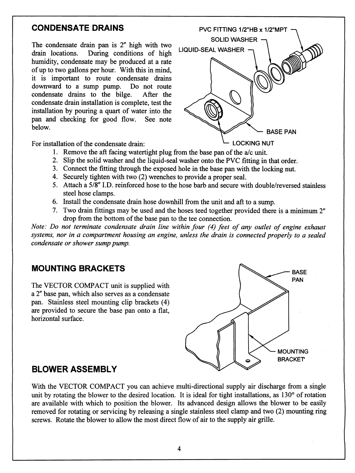
CONDENSATE
DRAINS
The
condensate
drain
pan
is
2"
high
with
two
drain
locations.
During
conditions
of
high
humidity,
condensate
may
be
produced
at
a
rate
of
up
to
two
gallons
per
hour.
With
this
in
mind,
it
is
important
to
route
condensate
drains
downward
to
a
sump
pump.
Do
not
route
condensate
drains
to
the
bilge.
After
the
condensate
drain
installation
is
complete,
test
the
installation
by
pouring
a
quart
of
water
into
the
pan
and
checking
for
good
flow.
See
note
below.
PVC
FITTING
1/2"HB
x
1/2"MPT
SOLID
WASHER
LIQUID-SEAL
WASHER
BASE
PAN
For
installation
of
the
condensate
drain:
*-
LOCKING
NUT
1.
Remove
the
aft
facing
watertight
plug
from
the
base
pan
of
the
a/c
unit.
2.
Slip
the
solid
washer
and
the
liquid-seal
washer
onto
the
PVC
fitting
in
that
order.
3.
Connect
the
fitting
through
the
exposed
hole
in
the
base
pan
with
the
locking
nut.
4.
Securely
tighten
with
two
(2)
wrenches
to
provide
a
proper
seal.
5.
Attach
a
5/8"
I.D.
reinforced
hose
to
the
hose
barb
and
secure
with
double/reversed
stainless
steel
hose
clamps.
6.
Install
the
condensate
drain
hose
downhill
from
the
unit
and
aft
to
a
sump.
7.
Two
drain
fittings
may
be
used
and
the
hoses
teed together
provided
there
is
a
minimum
2"
drop
from
the
bottom
of
the
base
pan
to
the
tee
connection.
Note:
Do
not
terminate
condensate
drain
line
within
four
(4)
feet
of
any
outlet
of
engine
exhaust
systems,
nor
in
a
compartment
housing
an
engine,
unless
the
drain
is
connected
properly
to
a
sealed
condensate or
shower
sump
pump.
MOUNTING
BRACKETS
The
VECTOR
COMPACT
unit
is
supplied
with
a
2"
base
pan,
which
also
serves
as
a
condensate
pan.
Stainless
steel
mounting
clip
brackets
(4)
are
provided
to
secure
the
base
pan
onto
a
flat,
horizontal
surface.
BLOWER
ASSEMBLY
MOUNTING
BRACKET
With
the
VECTOR
COMPACT
you
can
achieve
multi-directional
supply
air
discharge
from
a
single
unit
by
rotating
the
blower
to
the
desired
location.
It
is
ideal
for
tight
installations,
as
130°
of
rotation
are
available
with
which
to
position
the
blower.
Its
advanced
design allows
the
blower
to
be
easily
removed
for
rotating
or
servicing
by
releasing
a
single
stainless
steel
clamp
and
two
(2)
mounting
ring
screws.
Rotate
the
blower
to
allow
the
most
direct
flow
of
air
to
the
supply
air
grille.

SUPPLY
&
RETURN
AIR
GRILLES
Install
the
supply
air
grille
as
high
as
possible
in
a
location
that
will
provide
uniform
air
distribution
throughout
the
cabin,
grille
louvers
should
be
directed
upward.
The
return
air
grille
should
be
installed
as
low
and
close
to
the
a/c
unit as
possible
to
insure
direct
uninterrupted
airflow
to
the
evaporator.
The
return
air
grille
should
have
a
minimum
four
inches
(4")
or
clearance
in
front
of
it,
free
from
any
furniture
or
other
obstructions.
In
no
instance
should
a
supply
air
discharge
be
directed
towards
a
return
air
grille,
as
this
will
cause
the
system
to
short
cycle.
Allow
for
adequate
clearance
behind
the
supply
air
grille(s)
for
the
transition
box
and
ducting
connection.
The
following
table
shows
minimum
grille
sizes.
See
the
MAINTENANCE
section
of
this
manual
for
return
air
filter
cleaning
instructions.
DUCTING
Good
air
flow
is
critical
for
the
performance
of
the
entire
system.
It
is
highly
dependent
on
the
quality
of
the
ducting
installation.
The
ducting
should
be
run
as
straight,
smooth
and
taut
as
possible
minimizing
the
number
of
90
degree
bends
(two
tight
90
degree
bends
can
reduce
airflow
by
25%).
The
following
table
shows
minimum
duct
diameters
and
their
corresponding
supply
and
return
air
grille
minimum
areas
in
square
inches.
If
a
transition
box
is
used,
the
total
area
of
supply
air
ducts
going
out
of
the
box
should
equal
the
area
of
the
supply
duct
feeding
the
box.
To
calculate
the
square
inch area
of
a
round
duct,
multiply
the
radius
by
itself
(r2)
and
multiply
that
number
by
3.1416
(tt).
MODEL
DUCT
DIA
DUCT
AREA
R/A
GRILLE
S/A
GRILLE
7K
5"
dia
19.6
sq
in
88
sq
in
40
sq
in
10K
5"
dia
19.6
sq
in
98
sq
in
50
sq
in
12K
6"
dia
28.3
sq
in
140
sq
in
70
sq
in
16K
7"
dia
38.5
sq
in
168
sqin
84
sq
in
24K
8"
dia
50.3
sq
in
280
sq
in
140
sqin
The
following
is
a
summary
of
proper
ducting
connections:
1.
Pull
back
the
fiberglass
insulation
exposing
the
inner
mylar
duct
hose.
2.
Slide
the
mylar
duct
hose
around
the
mount
ring
until
it
bottoms
out.
3.
Screw
3
or
4
stainless
steel
sheet
metal
screws
through
the
duct
hose
into
the
transition
ring.
Make
sure
to
catch
the
wire
in
the
duct
hose
with
the
heads
of
the
screws.
Do
not
use
band
clamps,
as
the
hose
will
slide
off.
4.
Wrap
the
duct
tape
around
the
ducting
and
ring
joint
to
prevent
any
air
leaks.
5.
Pull
the
insulation
back
up
over
the
mylar
to
the
ring
and
tape
this
joint.
6.
Remove
excess
ducting
and
use
the
same
connection
method
at
the
s/a
grille.
All
ducting
should:
•
Be
appropriately
sized
for
each
application.
•
Run
as
smoothly
and
taut
as
possible.
•
Have
as
few
bends
or
loops
as
possible.
•
Be
securely
fastened
to
prevent
sagging
during
boat
operation.
•
Have
all
excess
ducting
lengths
trimmed
off.
•
Not
be
flattened
or kinked.
•
Insulated
when
located
in
high
heat
load
areas
(hull
side,
mechanical compartments,
etc.).
•
Be
properly
protected
against
potential
damage
when
routed
through
open
areas.
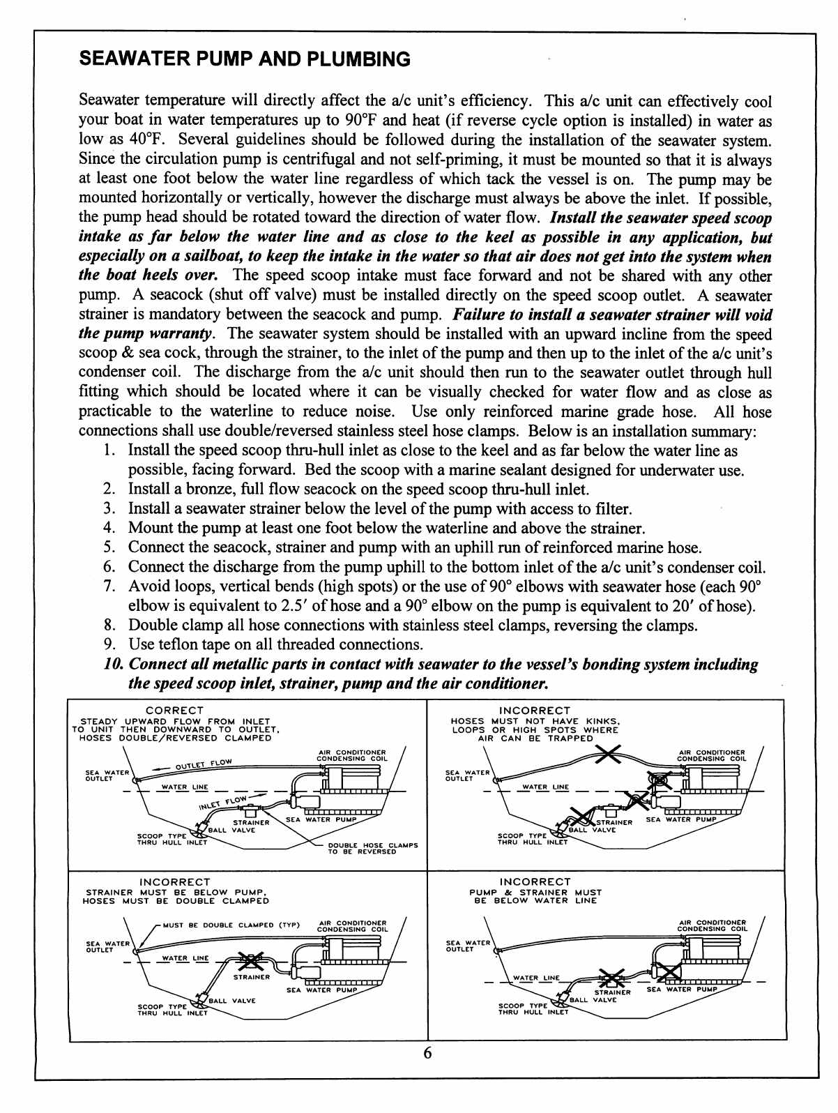
SEAWATER
PUMP
AND
PLUMBING
Seawater
temperature
will
directly
affect
the
a/c unit's
efficiency.
This
a/c
unit
can
effectively
cool
your
boat
in
water
temperatures
up
to
90°F
and
heat
(if
reverse
cycle
option
is
installed)
in
water
as
low
as
40°F.
Several
guidelines
should
be
followed
during
the
installation
of
the
seawater
system.
Since
the
circulation
pump
is
centrifugal
and
not
self-priming,
it
must
be
mounted
so
that
it
is
always
at
least
one
foot
below
the
water
line
regardless
of
which
tack
the
vessel
is
on.
The
pump
may
be
mounted
horizontally
or
vertically,
however
the
discharge
must
always
be
above
the
inlet.
If
possible,
the
pump
head
should
be
rotated
toward
the
direction
of
water
flow.
Install
the
seawater
speed
scoop
intake
as
far
below
the
water
line
and
as
close
to
the
keel
as possible
in
any
application,
but
especially
on
a
sailboat,
to
keep
the
intake
in
the
water
so
that
air
does
not
get
into
the
system
when
the
boat
heels
over.
The
speed
scoop
intake
must
face
forward
and
not
be
shared
with
any
other
pump.
A
seacock
(shut
off
valve)
must
be
installed
directly
on
the
speed
scoop
outlet.
A
seawater
strainer
is
mandatory
between
the
seacock
and
pump.
Failure
to
install
a
seawater
strainer
will
void
the
pump
warranty.
The
seawater
system
should
be
installed
with
an
upward
incline
from
the
speed
scoop
&
sea
cock,
through
the
strainer,
to
the
inlet
of
the
pump
and
then
up
to
the
inlet
of
the
a/c
unit's
condenser
coil.
The
discharge
from
the
a/c
unit
should
then
run
to
the
seawater
outlet
through
hull
fitting
which
should
be
located
where
it
can
be
visually
checked
for
water
flow
and
as
close
as
practicable
to
the
waterline
to
reduce
noise.
Use
only
reinforced
marine
grade
hose.
All
hose
connections
shall
use
double/reversed
stainless
steel
hose
clamps.
Below
is
an
installation
summary:
1.
Install
the
speed
scoop
thru-hull
inlet
as
close
to
the
keel
and
as
far
below
the
water
line
as
possible,
facing
forward.
Bed
the
scoop
with
a
marine
sealant
designed
for
underwater
use.
2.
Install
a
bronze,
full
flow
seacock
on
the
speed
scoop
thru-hull
inlet.
3.
Install
a
seawater
strainer
below
the
level
of
the
pump
with
access
to
filter.
4.
Mount
the
pump
at
least
one
foot
below
the
waterline
and
above
the
strainer.
5.
Connect
the
seacock,
strainer
and
pump
with
an
uphill
run
of
reinforced
marine
hose.
6.
Connect
the
discharge
from
the
pump
uphill
to
the
bottom
inlet
of
the
a/c
unit's
condenser
coil.
7.
Avoid
loops,
vertical
bends
(high
spots)
or
the
use
of
90°
elbows
with
seawater
hose
(each
90°
elbow
is
equivalent
to
2.5'
of
hose
and
a
90°
elbow
on
the
pump
is
equivalent
to
20'
of
hose).
8.
Double
clamp
all
hose
connections
with
stainless
steel
clamps,
reversing
the
clamps.
9.
Use
teflon
tape
on
all
threaded
connections.
10.
Connect
all
metallic
parts
in
contact
with
seawater
to
the
vesseVs
bonding
system
including
the
speed
scoop
inlet,
strainer,
pump
and
the
air
conditioner.
CORRECT
STEADY
UPWARD
FLOW FROM
INLET
TO
UNIT
THEN
DOWNWARD
TO
OUTLET,
HOSES
DOUBLE/REVERSED
CLAMPED
DOUBLE HOSE
CLAMPS
TO
BE
REVERSED
INCORRECT
HOSES
MUST
NOT
HAVE
KINKS,
LOOPS
OR
HIGH
SPOTS
WHERE
AIR
CAN
BE
TRAPPED
INCORRECT
STRAINER
MUST
BE
BELOW
PUMP,
HOSES
MUST
BE
DOUBLE
CLAMPED
INCORRECT
PUMP
&
STRAINER
MUST
BE
BELOW
WATER
LINE

ELECTRICAL
CONNECTIONS,
GROUNDING
AND
BONDING
All
a/c
units
have
a
terminal
strip
mounted
inside
the
electric
box.
The
terminal
strip
is
labeled
for
proper
connections
of
the
electrical
supply,
ground
wires
and
pump
circuits.
A
wiring
diagram
is
provided
in
the
electrical
box
and
in
this
manual.
The
correct
size
circuit
breaker
should
be
used
to
protect
the
system
as
specified
on
the
a/c
unit's
data
plate
label.
A
minimum
of
12
AWG
boat
cable
should
be
used
to
supply
power
to
the
a/c
unit
and
the
seawater
pump.
All
connections
shall
be
made
with
ring
or
fork
terminals.
Turn
off
a/c
power
supply
circuit
breaker
before
opening
electric
box.
Each
a/c
unit
installed
requires
its
own
dedicated
circuit
breaker.
If
there
is
only
one
a/c
unit
installed,
the
seawater
pump
does
not
require
a
circuit
breaker;
the
wiring
from
the
seawater
pump
is
connected
to
the
terminal
strip
in
the
electric
box.
If
two
or
more
a/c
units
use
the
same
seawater
pump,
the
pump
wires
will
be
connected
to
a
pump
relay
panel
(PRP)
which
in
turn
has
its
own
dedicated
circuit
breaker
sized
for
the
pump
(20
amp
max).
Please
see
the
wiring
diagram
furnished
with
the
PRP
(NOTE:
PRP
triac
must
have
its
mounting
screw
installed
in
order
to
dissipate
heat).
Electrical
connections
in
the
bilge
and/or
below
the
waterline
should
use
heat
shrink
type
butt
splices.
Field
wiring
must
comply
with
ABYC
electrical
codes.
Power
to
the
unit
must
be
within
the
operating
voltage
range
indicated
on
the
data
plate.
Properly
sized
fuses
or
HACR
circuit
breakers
must
be
installed
for
branch
circuit
protection.
See
data
plate
for
maximum
fuse/circuit
breaker
size
(mfs)
and
minimum
circuit
ampacity
(mca).
All
units
must
be
effectively
grounded
to
minimize
the
hazard
of
electrical
shock
and
personal
injury.
The
following
are
to
be
observed:
1.
AC
(alternating
current)
grounding
(green
wire)
must
be
provided with
the
AC
power
conductors
and
connected
to
the
ground
terminal
(marked
"GRND")
at
the
AC
power
input
terminal
block
of
the
unit(s),
per
ABYC
standard
E-8,
or
equivalent.
2.
Connections
between
the
vessel's
AC
system
grounding
conductor
(green
wire)
and
the
vessel's
DC
(Direct
Current)
negative
or
bonding
system
should
be
made
as
part
of
the
vessel's
wiring,
per
ABYC
standard
E-9,
or
equivalent.
3.
When
servicing
or
replacing
existing
equipment
that
contains
a
chassis-mounted
ground
stud,
the
service
person
or
installer
must
check
the
vessel's
wiring
for
the
existence
of
the
connection
required
in
item
2
above.
ABYC
standards
are
available
from:
American
Boat
and
Yacht
Council
3069
Solomon's
Island
Rd.
Edgewater,
MD
21036
Telephone:
(410)
956-1050
The
a/c
unit
must
be
connected
to
the
ship's
bonding
system
to
prevent
corrosion
due
to
stray
electrical
current
or
voltage.
All
pumps,
metallic
valves
and
fittings
in
the
seawater
circuit
that
are
isolated
from
the
a/c
unit
by
PVC
or
rubber
hoses
must
be
individually
bonded
to
the
vessels
bonding
system
also.
This
will
help
eliminate
any
possibility
of
corrosion
due
to
stray
current
or
voltage.
FAILURE
TO
PROPERLY
GROUND
AND
BOND
THE
SYSTEM
WILL
VOID
WARRANTY!
3
PHASE
NOTICE
It
is
extremely
important
to
insure
that
wiring
and
phase
sequencing
of
a
three
phase
power
source
is
correct.
Marine
wiring
standards
call
for
power
source
phases
LI,
L2,
and
L3
to
be
color-coded
BLACK,
WHITE,
and
RED,
respectively.
These
must
be
connected
to
the
unit
with
the
proper
sequence,
otherwise,
it
will
not
operate
properly.
If
the
wiring
sequence
is
incorrect,
the
unit's
compressor
{Scroll
type
only)
and
pump
(if
applicable)
will
run
in
the
reverse
direction
at
a
significantly
increased
noise
level.

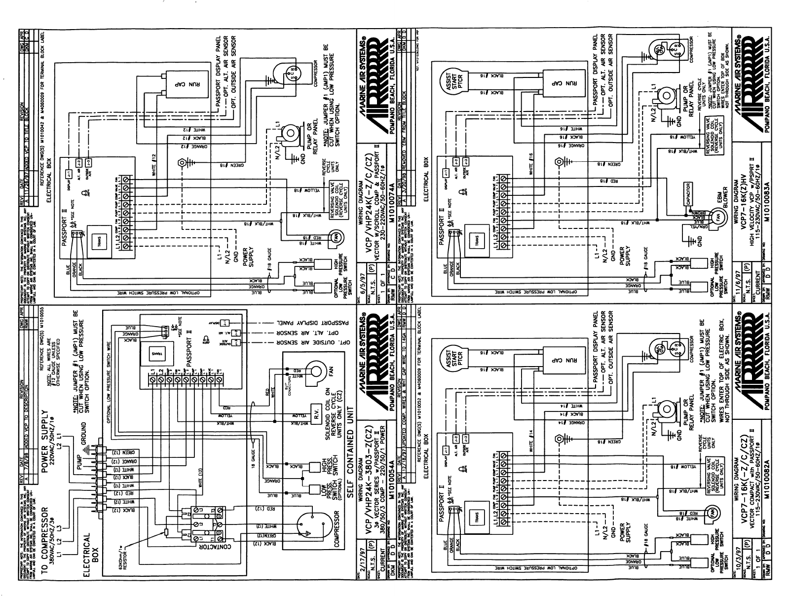
VECTOR
COMPACT
WIRING
DIAGRAMS
1
GREEN
2
BLACK
3
WHT/BLK
4
RED
5
ORANGE
6
YELLOW
7
BLK/RED
8
WHltE
SELF
CONTAINED
UNIT
MALE
FEMALE
POLARIZED
PLUG
DETAIL
3/19/98
N.T.S.
WIRING
DIAGRAM
VCM24K-Z
3PH
VECTOR
COMPACT
3*
24K
WITH
230VAC/50-60HZ/3g
MCP
M1010090A
/III
/MARINE/IR
SYSTEMS®
mi))))
POMPANO
BEACH,
FLORIDA
U.S.A.
oktaino)
m
ths
REV
DATE
AIR
SYSTEMS
NC
ANY
—
*—&
>WFULL
AND
CAN
BE
CCNTESTEO
M
A
COURT
OT
b
POWER
SUPPLY
GND
POWER
SUPPLY
•=BUH
CONNECTORS
FIELD
WIRING
1
CREEN
2
BUCK
3
WHT/BLK
4
REO
5
ORANCE
6
YELLOW
7
BLK/RED
/B
WHITE
SELF
CONTAINED
UNIT
MALE
FEMALE
POLARIZED
PLUG
DETAIL
1
GREEN
2
SLACK
3
WHT/BLK
4
RED
5 ORANGE
6
YELLOW
7
BLK/RED
8
WHITE
SELF
CONTAINED
UNIT
MALE
FEMALE
POLARIZED
PLUG
DETAIL
1/19/98
N.T.S.
WIRING
DIAGRAM
VCM7-16K(-Z/C/CZ)
VECTOR
COMPACT
with
MCP
115-23OVAC/5O-6OHZ/10
M1010086
/HARINE
yiiR
SYSTEMS®
1/30/98
N.T.S.
POMPANO
BEACH,
FLORIDA
U.S.A.
WIRING
DIAGRAM
VCM24K(-Z/C/CZ)
VECTOR
COMPACT
with
MCP
115-230VAC/50-60HZ/1*
M1010087
yVlARINE/IR
SYSTEMS®
POMPANO
BEACH.
FLORIDA
U.S.A.
/B/9B
AUUfcU
VIP
IU
I
PROPRIETARY
NOTE:
THE
INFORMATION
CONTAINED
W
THS
ATTEMPT
TO
COPT
OR
TO
COMPRESSOR
38OVAC/5OHZ/30
L1
L2 L3
LJ
REFERENCE
DWC(S)
M1010055
NOTE:
ALJL
WIRES
ARE
7i2
GAUGE
UNL£SS
OTHERWISE
SPECIFIED
POWER
SUPPLY
220VAC/50HZ/1*
L2
L1
'NOTE:
JUMPER
#1
(JMP1)
MUST
BE
PUM.P
-
rRnuwn
CUT
WHEN
USING
LOW
PRESSURE
^GROUND
SOLENOID
COIL
ON
REVERSE
CYCLE
UNITS
ONLY
(CZ)
SELF
CONTAINED
UNIT
-ML
11/26/9
ADDED
VCP
TO
TITLE
BLOC
REFERENCE
DWC(S)
Ml010042
&
M406C009
FOR
TERMINAL
BLOCK
LABEL
ELECTRICAL
BOX
!
L
PASSPORT
DISPLAY
PANEL
•
OPT.
ALT.
AIR
SENSOR
OPT.
OUTSIDE
AIR
SENSOR
*NOTE:
JUMPER
#1
(JMP1)
MUST
BE
CUT
WHEN
USING
LOW
PRESSURE
SWITCH
OPTION.
2/17/97
*N.T.S.
CURRENT
WIRING
DIAGRAM
VCP/VHP24K-3803-Z(CZ)
3*
VECTOR
SERIES
w/PASSPORT
E
380/50/3
COMP
-
220/50/1
POWER
7V1AR1NE/HR
SYSTEMS®
6/5/97
"N.T.5.
Iff)
1
OF
1
WIRING
DIAGRAM
VCP/VHP24K(-Z/C/CZ)
VECTOR
W/SCROLL
COMP
&
PASSPORT
23O-22OVAC/5O-6OHZ/10
/MARINE
/IR
SYSTEMS®
POMPANO
BEACH,
FLORIDA
U.S.A.
POMPANO
BEACH,
FLORIDA
U.S.A.
REFERENCE
DWC(S)
M1O1OO52
it
M4060009
FOR
TERMINAL
BLOCK
LABEL
ELECTRICAL
BOX
ELECTRICAL
BOX
L-
PASSPORT
DISPLAY
PANEL
'
OPT.
ALT.
AIR
SENSOR
I
OPT.
OUTSIDE
AIR
SENSOR
D
OPTIONAL
HIGH
LOW
PRESSURE
PRESSURE
SWITCH
SWITCH
•NOTE:
JUMPER
#1
(JMP1)
MUST
BE
CUT
WHEN
USING
LOW
PRESSURE
SWITCH
OPTION.
WIRES
ENTER
TOP
OF
ELECTRIC BOX,
NOT
THROUGH
SIDE
AS
SHOWN.
OPTIONAL
HIGH
LOW
PRESSURE
PRESSURE
SWITCH
SWITCH
EBM
'BLOWER
REVERSING
VALVE
SOLENOID
COIL
(REVERSE
CYCLE
UNITS
ONLY)
COMPRESSOR
REVERSE
CYCLE
UNITS
ONLY
•NOTF:
JUMPER
fi
(JMP1)
MUST
BE
CUT
WHEN
USING
LOW
PRESSURE
SWITCH
OPTION.
WIRES
ENTER
TOP
OF
BOX
NOT
THROUGH
SIDE
AS SHOWN.
10/3/97
"N.T.S.
1
OF
1
RMW
I
D D
WIRING
DIAGRAM
VCP7-16K(-Z/C/CZ)
VECTOR
COMPACT
with
PASSPORT
0
115-230VAC/50-60HZ/1
g
M1010082A
/MARINE
yllRSYSTEMSp
POMPANO
BEACH,
FLORIDA
U.S.A.
11/6/97
"!N.T.S.
CURRENT
RMW
|
D D
WIRING
DIAGRAM
VCP7-16K(Z)HV
HIGH
VELOCITY
VCP
w/PSPRT
H
115-23OVAC/5O-6OHZ/10
M1010083A
/V1AR1NE
y||R
SYSTEMS®
POMPANO
BEACH.
FLORIDA
U.S.A.

MANUAL
CONTROL
PANEL
(MCP)
INSTALLATION
The
MCP
should
be
located
within
cap
tube
length
of
the
a/c
unit.
The
3
knob
MCP
is
configured
either
vertically
(shown)
or
horizontally.
The
cut
out
size
is
2.5"
by
7.0",
see
MCP
for
orientation.
Once
the
cut
out
is
made,
carefully
uncoil
the
copper
cap
tube
with
return
air
sensor
(copper
bulb)
and
route
the
control
wires
and
cap
tube
through
the
hole
and
back
to
the
a/c
unit
using
caution
not
to
kink
the
cap
tube.
Mount
the
return
air
sensor
into
the
clips
provided
on
the
evaporator
coil.
If
the
return
air
sensor
cannot
be
mounted
on
the
evaporator
coil,
mount
it
behind
the
return
air
grille.
The
sensor
must
be
mounted
in
the return
air
stream.
Make
electrical
connections
according
to
the
wiring
diagram
found
in
the
electric
box
and/or
in
the
operations
manual.
MCP
OPERATION
1)
Ensure
seawater
intake
ball
valve
(sea
cock)
is
open.
2)
Turn
SYSTEM
SWITCH
control
knob
to
OFF.
3)
Turn
on
AC
circuit
breaker.
If
the
seawater
pump
has
its
own
circuit
breaker,
turn
that
on
too.
4)
Turn
the
SYSTEM
SWITCH
control
knob
to
START;
this
energizes
the
fan
and
seawater
pump.
Turn
THERMOSTAT
control
knob
to
the
coolest
position
by
rotating
fully
clockwise.
If
system
has
reverse
cycle,
turn
knob
counter-clockwise
for
heat.
5)
Check
for
a
steady
solid
stream
of
seawater
from
the
overboard
discharge.
6)
Turn
FAN
SPEED
control
knob
clockwise
to
highest
setting.
7)
Verify
that
the
fan
is
running
and
that
there
is
steady
airflow
out
of
the
supply
air
grille.
8)
Turn
the
SYSTEM
SWITCH
to
RUN;
this
will
start
the
compressor.
The
indicator
light
on
the
control
will
illuminate.
9)
To
set
the
thermostat,
allow
sufficient
time
for
the
unit
to
cool/heat
the
area
to
the
desired
temperature.
When
the
area
is
sufficiently
cooled/heated,
turn
the
thermostat
knob
slowly
toward
the
center
position
until
it
clicks
once
(the
indicator
light
will
turn
off).
The
thermostat
is
now
set
to
maintain
a
constant
temperature.
While
heating,
if
the
ambient
temperature
is
less
than
50°F,
set
the
FAN
SPEED
control
knob
to
low
for
five
to
ten
minutes
until
the
unit
begins
to
heat
well,
then
increase
the
fan
speed
for
more
heat
output.
START
SYSTEM
SWITCH
FAN
SPEED
THERMOSTAT
O
/MARINE/URSVSIEMS&
2.5"
CUT
OUT
-3.75"
PANEL-
O
5
„
b
t^ °°
The
thermostat
on
the
MCP
control
panel
serves
to
cycle
the
compressor
on
and
off
and
provide
an
automatic
changeover
from
cooling
to
heating
(reverse
cycle
only)
with
a
3.5°
differential.
Rotating
the
thermostat
to
the
left
after
it
has
been
set
for
cooling
will
cause
the
unit
to
heat.
If
you
rotate
the
thermostat
to
the
right,
the
unit
will
cool.
If
the
thermostat
is
left
stationary
after
being
set,
the
unit
will
cycle
from
cooling
to
neutral,
or
heating
to
neutral
depending
on
the
requirement.
Note:
Do
not
turn
the
unit
off
and
immediately
turn
it
back
on.
Wait
at
least
30
seconds.
10
PASSPORT
II
DISPLAY
PANEL
INSTALLATION
COOL
LED
FAN
LED
POWER
BUTTON
HEAT
LED
FAN
BUTTON
DISPLAY
WINDOW
UP
&
DOWN
BUTTONS
AIR
SENSOR
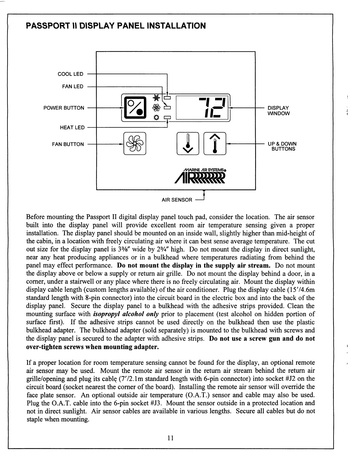
Before
mounting
the
Passport
II
digital
display
panel
touch
pad,
consider
the
location.
The
air
sensor
built
into
the
display
panel
will
provide
excellent
room
air
temperature
sensing
given
a
proper
installation.
The
display
panel
should
be
mounted
on
an
inside
wall,
slightly
higher
than
mid-height
of
the
cabin,
in
a
location
with
freely
circulating
air
where
it
can
best
sense
average
temperature.
The
cut
out
size
for
the
display
panel
is
3%"
wide by
2%"
high.
Do
not
mount
the
display
in
direct
sunlight,
near
any
heat
producing
appliances
or
in
a
bulkhead
where
temperatures
radiating
from
behind
the
panel
may
effect
performance.
Do
not
mount
the
display
in
the
supply
air
stream.
Do
not
mount
the
display
above
or
below
a
supply
or
return
air
grille.
Do
not
mount
the
display
behind
a
door,
in
a
corner,
under
a
stairwell
or
any
place
where
there
is
no
freely
circulating
air.
Mount
the
display
within
display
cable
length
(custom
lengths
available)
of
the
air
conditioner.
Plug
the
display
cable
(1574.6m
standard
length
with
8-pin
connector)
into
the
circuit
board
in
the
electric
box
and
into
the
back
of
the
display
panel.
Secure
the
display
panel
to
a
bulkhead
with
the
adhesive
strips
provided.
Clean
the
mounting
surface
with
isopropyl
alcohol
only
prior
to
placement
(test
alcohol
on
hidden
portion
of
surface
first).
If
the
adhesive
strips
cannot be
used
directly
on
the
bulkhead
then
use
the
plastic
bulkhead
adapter.
The
bulkhead
adapter
(sold
separately)
is
mounted
to
the
bulkhead
with
screws
and
the
display
panel
is
secured
to
the
adapter
with
adhesive
strips.
Do
not use
a
screw
gun
and
do
not
over-tighten
screws
when
mounting
adapter.
If
a
proper
location
for
room
temperature
sensing
cannot
be
found
for
the
display,
an
optional
remote
air
sensor
may
be
used.
Mount
the
remote
air
sensor
in
the
return
air
stream
behind
the
return
air
grille/opening
and
plug
its
cable
(772.1m
standard
length
with
6-pin
connector)
into
socket
#J2
on
the
circuit
board
(socket nearest
the
corner
of
the
board).
Installing
the
remote
air
sensor
will
override
the
face
plate
sensor.
An
optional outside
air
temperature
(O.A.T.) sensor
and
cable
may
also
be
used.
Plug
the
O.A.T.
cable
into
the
6-pin
socket
#J3.
Mount
the
sensor
outside
in
a
protected
location
and
not
in
direct
sunlight.
Air
sensor
cables
are
available
in
various
lengths.
Secure
all
cables
but
do
not
staple
when
mounting.
11
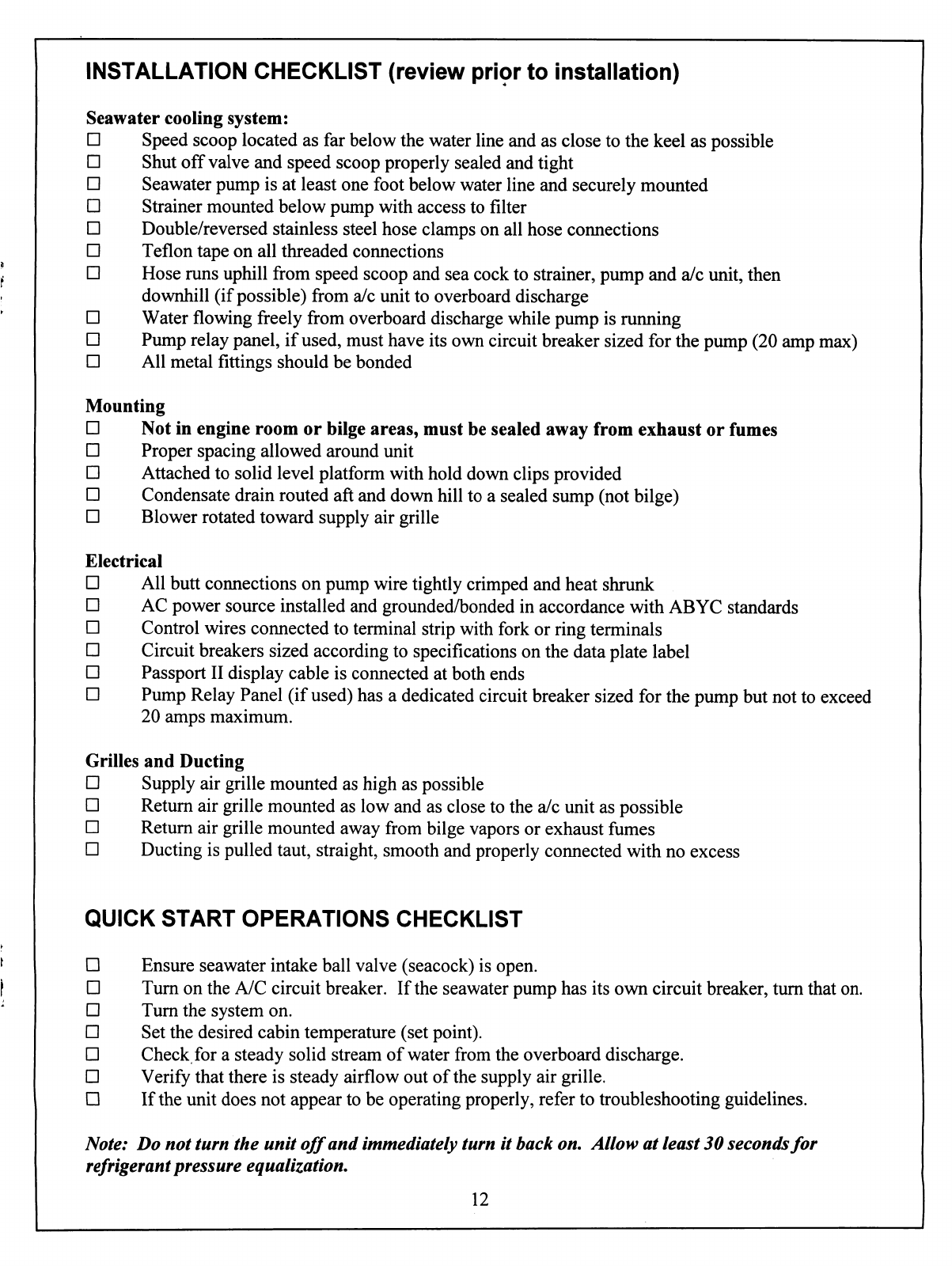
INSTALLATION
CHECKLIST
(review
prior
to
installation)
Seawater
cooling
system:
□
Speed
scoop
located
as
far
below
the
water
line
and
as
close
to
the
keel
as
possible
□
Shut
off
valve
and
speed scoop
properly
sealed
and
tight
□
Seawater
pump
is
at
least
one
foot
below
water
line
and
securely
mounted
□
Strainer
mounted
below
pump
with
access
to
filter
□
Double/reversed
stainless
steel
hose
clamps
on
all
hose
connections
□
Teflon
tape
on
all
threaded
connections
□
Hose
runs
uphill
from
speed
scoop
and
sea
cock
to
strainer,
pump
and
a/c
unit,
then
downhill
(if
possible)
from
a/c
unit
to
overboard
discharge
□
Water
flowing
freely
from
overboard
discharge
while
pump
is
running
□
Pump
relay
panel,
if
used,
must
have
its
own
circuit
breaker
sized
for
the
pump
(20
amp
max)
□
All
metal
fittings
should
be
bonded
Mounting
D
Not
in
engine
room
or
bilge
areas,
must
be
sealed
away
from
exhaust
or
fumes
□
Proper
spacing
allowed
around
unit
□
Attached
to
solid
level
platform
with
hold
down
clips
provided
□
Condensate
drain
routed
aft
and
down
hill
to
a
sealed
sump
(not
bilge)
□
Blower
rotated
toward
supply
air
grille
Electrical
□
All
butt
connections
on
pump
wire
tightly
crimped
and
heat
shrunk
□
AC
power
source
installed
and
grounded/bonded
in
accordance
with
ABYC
standards
□
Control
wires
connected
to
terminal
strip
with
fork
or
ring
terminals
□
Circuit
breakers
sized
according
to
specifications
on
the
data
plate
label
□
Passport
II
display
cable
is
connected
at
both
ends
□
Pump
Relay
Panel
(if
used)
has
a
dedicated
circuit
breaker
sized
for
the
pump
but
not
to
exceed
20
amps
maximum.
Grilles
and
Ducting
□
Supply
air
grille
mounted
as
high
as
possible
□
Return
air
grille
mounted
as
low
and
as
close
to
the
a/c
unit as
possible
□
Return
air
grille
mounted
away
from
bilge
vapors
or
exhaust
fumes
□
Ducting
is
pulled
taut,
straight,
smooth
and
properly
connected
with
no
excess
QUICK
START OPERATIONS
CHECKLIST
□
Ensure
seawater
intake
ball
valve
(seacock)
is
open.
□
Turn
on
the
A/C
circuit
breaker.
If
the
seawater
pump
has
its
own
circuit
breaker,
turn
that
on.
□
Turn
the
system
on.
□
Set
the
desired
cabin
temperature
(set
point).
□
Check
for
a
steady
solid
stream
of
water
from
the
overboard
discharge.
□
Verify
that
there
is
steady
airflow
out
of
the
supply
air
grille.
□
If
the
unit
does
not
appear
to
be
operating
properly,
refer
to
troubleshooting
guidelines.
Note:
Do
not
turn
the
unit
off
and
immediately
turn
it
back
on.
Allow
at
least
30
seconds
for
refrigerant
pressure
equalization.
12

PASSPORT
II
CONTROL
POWER
BUTTON:
Press
and
release
to
turn
unit
on
and
off.
NOTE:
To
"press
and
release"
a
button,
press
and
hold
for
one
second
and
then
release.
FAN
BUTTON:
Press
and
hold
until
the
letter
"A"
appears
for
automatic
fan
speed
or
the
numbers
"1"
(slow)
through
"6"
(fast)
appear
for
manual
fan
speed.
Fan
may
be
used
while
a/c
is
off.
UP
&
DOWN
BUTTONS:
Press
and
hold
either
button
until
desired
temperature
(set
point)
is
displayed.
Press
either
button
momentarily
to
show
current
set
point.
Range
=
60°-85°F.
COOL
LED:
Lights
when
the
compressor
is
running
in
cool
mode
or
in
automatic
mode
while
cooling.
FAN
LED:
Lights
when
fan
is
on
in
manual
mode.
HEAT
LED:
Lights
when
the
compressor
is
running
in
heat
mode,
in
automatic
mode
while
heating
or
if
optional
electric
heat
is
installed
and
operating.
DISPLAY
WINDOW:
Shows
current
cabin
temperature.
It
can
also
show
outside
air
temperature
if
the
optional
O.A.T.
sensor
is
installed.
Also
used
in
viewing
and
setting
program
parameters.
AIR
SENSOR:
Cabin
temperature
is
detected
by
the
face
plate
air
sensor,
located
in
the
bottom
edge
of
the
display.
A
remote
air
sensor
can
be
installed
if
needed.
Installing
the
remote
air
sensor
will
override
the
face
plate
sensor.
BLANK
DISPLAY
FOR
NIGHTTIME
OPERATION:
Press
the
FAN
and
DOWN
buttons
simultaneously
to
blank
the
display
for
nighttime
operation.
The
appropriate
LEDs
will
remain
lit
during
cooling
and
heating.
When
the
desired
temperature
has
been
achieved,
the
middle
segment
of
the
display
window
will
remain
lit
to
indicate
that
the
system
is
on.
Press
any
button
to
return
to
normal
display
mode.
OUTSIDE
AIR
TEMPERATURE:
When
the
optional
outside
air
sensor
is
installed,
press
the
UP
and
DOWN
buttons
simultaneously
to
display
the
outside
air
temperature.
The
outside
air
sensor
should
not
be
mounted
in direct
sunlight.
MODES
OF
OPERATION
COOL
ONLY
MODE:
When
the
Passport
II
is
configured
for
cool
only
mode,
only
cooling
systems
will
be
operated
as
required.
When
the
temperature
drops
below
the
set
point
the
system
will
not
automatically
switch
into
the
heating
mode.
HEAT
ONLY
MODE:
When
the
controller
is
programmed
for
heating
mode,
only
the
heating
system
will
be
selected
for
operation
as
required.
Should
the
temperature
rise
above
the
set
point
the
system
will
not
switch
to
the
cooling
mode
automatically.
AUTOMATIC
MODE:
When
the
controller
is
configured
for
the
automatic
mode,
both
heating
and
cooling
will
be
supplied
as
required.
The
heat
and
cool
LED
indicators
will
light
according
to
which
mode
is
operating.
Temperature
differential
in
a
given
mode
will
be
maintained
at
2°F,
however,
a
4°F
difference
is
required
to
allow
the control
to
change modes.
13

HUMIDITY
MODE:
While
the
system
is
on,
press
the
POWER
and
the
DOWN
buttons
simultaneously
to
enter
the
humidity
or
moisture
control
mode.
The
characters
"HU-1"
will
appear
in
the
temperature
display.
Every
four
hours,
the
fan
is
started
and
air
is
circulated
for
thirty
minutes.
During
this
time
the
air
temperature
is
sampled
and
entered
into
memory.
The
cooling
cycle
is
then
started
and
continues
until
the
temperature
is
lowered
2°F.
The
compressor
is
allowed
a
maximum
of
one
hour
running
time
to
reach
the
desired
temperature.
Four
hours
after
the
temperature
is
satisfied
or
the
compressor
times
out,
the
cycle
is
repeated.
During
the
cycle,
the
cool
LED
will
be
lit
when
the
compressor
is
running.
Humidity
mode
is
provided
to
maintain
a
specific
temperature
and
humidity
range
when
the
vessel
is
unoccupied
for
extended
periods
of
time.
AUTOMATIC
FAN
MODE:
Press
and
hold
the
FAN
button
until
the
letter
"A"
appears
in
the
display
window.
Automatic
fan
mode
allows
the
control
to
determine
fan
speeds
based
on
the
room
temperature.
The
closer
the
room
temperature
gets
to
the
set
point,
the
slower
the
fan
will
run
while
in
cool
mode.
This
permits
a
balance
between
the
most
efficient
temperature
control
and
the
slowest
fan
speed.
See
programmable
parameter
"U
9"
to
reverse
the
fan
speeds
while
in
heat
mode.
The
fan
LED
will
not
be
lit
during
automatic
fan
mode.
MANUAL
FAN
MODE:
Press
and
hold
the
FAN
button
during
normal
operation
to
select
one
of
the
six
manual
fan
speeds
available.
Six
(6)
is
the
highest
and
one
(1)
represents
the
lowest
speed
available.
When
a
manual
fan
speed
has
been
selected
the
fan
LED
will
be
lit.
NOTE:
High
and
low
fan
speeds
can
be
further
tailored
to
suit
the
user
by
adjusting
the
fan
limits.
See
programming
modes
"U
2"
and
"U
3".
CIRCULATION
MODE
(FAN
ONLY):
With
the
system
off,
press
and
hold
the
FAN
button
until
the
desired
fan
speed
is
indicated
by
the
numbers
"1"
(slow)
through
"6"
(fast).
To
turn
the
fan
off
press
and
hold
the
FAN
button
until
the
number
"0"
appears
in
the
display
window.
PROGRAMMING
THE
PASSPORT
II
The
program
mode
is
used
to
adjust
operating
parameters
to
tailor
the
system
for
efficient
operation
and
to
allow
for
user
flexibility.
Installation
variables
such
as ducting,
sensor
location
and
system
layout
effect
the
operation
of
the
overall
system.
Custom
programming
allows
the
system
to
operate
as
efficiently
as
possible
in
any
given
installation.
TO
ENTER
PROGRAM
MODE:
With
the
system
off,
press
and
hold
the
POWER
button
for
five
seconds
until
the
letter
"U"
appears
in
the
display
window.
Release
the
button
and
the
first
parameter
setting
appears
followed
by
"U
1".
TO
UNLOCK
PROGRAM
MODE:
After
entering
the
program
mode,
simultaneously
press
and
release
the
POWER
and
DOWN
buttons.
TO
SELECT
PROGRAM
PARAMETER:
Press
and
hold
the
FAN
button
to
scroll
through
the
parameters
indicated
by
the
program
number.
Programs
are
described
in
the
following
table.
TO
CHANGE
THE
PROGRAM
PARAMETER:
Use
the
UP
and
DOWN
buttons
to
select
data
or
set
the
desired
limits.
The
range
of
parameter
settings
is
listed
in
the
following
table.
TO
RESET
DEFAULT
SETTINGS:
With
the
system
off,
press
and
hold
the
POWER
button
for
ten
seconds
until
the
software
version
number
(A##)
appears
in
the
display
window.
14

TO
LOCK
NEW
DEFAULT
SETTINGS:
Once
the
desired
program
changes
have
been
made
and
before
exiting
the
program
mode,
simultaneously
press
and
release
the
UP
and
DOWN
buttons.
Locking
new
defaults
will
render
the
factory
defaults
obsolete.
Make
note
of
the
new
defaults
in
the
following
chart
for
future
reference.
TO
EXIT
PROGRAM
MODE:
Press
the
POWER
button
or
press
no
button
for
sixty
seconds.
The
software
version
number
is
displayed
for
one
second
prior
to
exiting
the
program
mode.
PROGRAMMABLE
PARAMETERS:
Program
Number
U1
U2
U3
U4
U5
U6
U7
U8
U9
U10
U11
U12
U15
Description
Operating
Mode
High
Fan
Speed
Limit
Low
Fan
Speed
Limit
Compressor
Staging
Time
Delay
Temperature
Calibration
Compressor
Fail-Safe
Protection
HHH
=
high
freon
pressure
PPP
=
low
freon
pressure
(option)
Fahrenheit
or
Celsius
Temperature
Display
Not
Used
Reversed
Fan
Speeds
During
Heating
Continuous
Fan
Operation
or
Cycle
Fan
with
Compressor
Reverse
Cycle
or
Electric
Heat
Option
Installed
Fan
Motor
Type
Selection
De-icing
Cycle
Default
Setting
Oorl*
85
50
15 or
135*
0
3
0
-
1
1
0
Set
at
Factory
0
New**
Default
Range
0
=
Automatic
Mode
1
=
Cool
Only
Mode
2
=
Heat
Only
Mode
56-85
30-55
5-135
Seconds
±10°F
0
=
Fail
Safe
Protection
OFF
1
=
Continuous
Restarts,
No
Display
2
=
Continuous
Restarts,
With
Display
3
=
3
Failures
w/Display,
Reset
Required
0
=
°F
1=°C
-
0
=
Fan
speed
decreases
as
set
point
is
approached.
1
=
Reversed
Fan
Speeds
0
=
Cycle
Fan
with
Compressor
1
=
Continuous
Fan
Operation
0
=
Reverse
Cycle
Heat
1
=
Electric
Heat
0
=
Shaded
Pole
Fan Motor
1
=
Split
Capacitor
Fan
Motor
0
=
Off,
1
=
One
Minute
2
=
Two
Minutes,
3
=
Three
Minutes
*
Specific
default
settings
for
cool
only
a/c
units
(no
heat
option
installed)
should
not
be
changed.
**
Default
parameter
settings
may
be
reprogrammed
by
user,
enter
new
default
settings
in
this
column.
U
1
OPERATING
MODE:
The
operating
mode
is
used
to select
heating,
cooling,
or
automatic
modes.
Zero
(0)
selects
automatic
mode,
one
(1)
selects
cooling
mode
and
two
(2)
selects
heating
mode.
Systems
that
do
not
have
heating
capabilities
should
be
programmed
for
cooling
mode
(1).
The
factory
default
is
zero
(0)
for
automatic
mode
for
reverse
cycle
units
or
one
(1)
for
cool
only
mode
for
units
with
no
heat
option
installed.
U
2
HIGH
FAN
SPEED
LIMIT:
The
high
fan
speed
limit
can
be
tailored to
suit
various
motors
and
operating
conditions.
The
range
of
values
is
56
through
85
in
arbitrary
units.
The
factory
default
is
85.
15

U
3
LOW
FAN
SPEED
LIMIT:
The
low
fan
speed
limit
determines
the
lowest
output
allowed
for
the
low
fan
speed.
The
range
of
values
is
30
through
55
in
arbitrary
units.
The
factory
default
is
50.
Both
the
high
and
low
fan
limits
may
be
adjusted
as
follows:
While
the
system
is
off,
start
the fan
by
pressing
and
holding
the
FAN
button
until
the
number
"1"
appears
in
the
display.
Enter
the
program
mode
while
the
fan
is
running
and
select
"U2"
or
"U3".
Raising
and
lowering
the
fan
limits
while
the
fan
is
running
allows
the
programmer
to
experience
fan
speed
changes
as
they
are
made.
Once
the
high
and
low
fan
speed
limits
are
set,
the
system
will
automatically
reprogram
itself
to
produce
six
equally
spaced
fan
speeds
between
them.
U
4
COMPRESSOR
STAGING
TIME
DELAY:
The
compressor
staging
time
delay
is
provided
for
use
where
more
than
one
a/c
system
is
being
operated
from
the
same
power
source.
Setting
the
staging
delays
at
different
intervals
allows
for
only
one
compressor
to
start
at
a
time
to
lessen
the
amperage
load
on
the
power
source.
The
minimum
delay
is
five
(5)
seconds
and
the
maximum
is
one
hundred
thirty
five
(135)
seconds.
The
factory
default
setting
is
fifteen
(15)
seconds
for
reverse
cycle
units
or
one
hundred
thirty
five
(135)
seconds
for
units
with
no
heat
option
installed.
U
5
TEMPERATURE
CALIBRATION:
Use
this
feature
to calibrate
the
air
sensor
within
a
range
of
±
10°F.
The
factory
default
is
0°F.
U
6
COMPRESSOR
FAIL-SAFE
PROTECTION:
This
feature
is
provided
to
monitor
the
refrigerant
circuit.
When
a
high
head
pressure
condition
occurs
the
display
will
flash
"HHH",
when
the
refrigerant
system
is
low
on
pressure
"PPP"
will
flash
only
if
the
optional
low
pressure
switch
is
installed.
This
display
indicates
that
the
system
requires
maintenance.
See
the
troubleshooting
guidelines
in
this
manual.
The
factory
default
is
three
(3).
The
four
parameter
settings
are:
Zero
(0):
Turns
off
all
protection,
no
action
is
taken
and
no
message
displayed.
One
(1):
No
message
displayed
with
90
seconds
between
continuous
restarts.
Two
(2):
Message
displayed
with
90
seconds
between
continuous
restarts.
Three
(3):
Message
displayed
with
three
90
second
restarts,
manual
reset
is
required.
U
7
FAHRENHEIT
OR
CELSIUS
TEMPERATURE
DISPLAY:
The
PASSPORT
II
can
display
temperature
in
either
degrees
Fahrenheit
(°F)
or
degrees
Celsius
(°C).
Setting
to
zero
(0)
displays
°F
and
setting
to
one
(1)
displays
°C.
The
factory
default
is
zero
(0).
U8
NOT
USED
U
9
REVERSED
FAN
SPEEDS
DURING
HEATING:
During
normal
operation
in
the
cooling
mode
with
the
fan
speed
set
to
"A"
(automatic),
the
fan
speed
is
reduced
as
the
set
point
temperature
is
approached.
During
heating,
this
is
not
always
the
preferred
method
of
operation.
When
this
parameter
is
set
to
one
(1),
the
fan
speed
will
increase
as
the
set
point
is
approached
during
heating.
This
will
reduce
head
pressure
by
increasing
airflow
across
the
coil
as
the
set
point
is
approached.
Setting
the
parameter
to
zero
(0)
will
cause
the
fan
speed
to
decrease
as
the
set
point
is
approached
during
heating,
as
it
does
in
the
cooling
mode.
The
factory default
is
one
(1).
U10
CONTINUOUS
FAN
OPERATION
OR
CYCLE
FAN
WITH
COMPRESSOR:
The
fan
can
be
programmed
to
run
continuously
while
the
system
is
on,
or
can
be
allowed
to
cycle
with
the
compressor.
When
cycled
with
the
compressor,
the
fan
will
only
operate
when
cooling
or
reverse
cycle
heating
is
called
for.
To
cycle
the
fan
with
the
compressor,
select
zero
(0).
To
operate
the fan
continuously,
select
one
(1).
The
factory
default
is
one
(1).
16
Table of contents
Other Marine Air Systems Marine Equipment manuals


