Marini Quarry Votager Operating instructions

MARINI QUARRIES GROUP S.
R.L.
Unipersonale
Via Beura, 44 •28844 Villadossola (VB) •ITALY
Tel.: +39 0324 575106 •Fax: +39 0324 54096
Web : www.MariniQG.it
E-mail: M[email protected]

Dear Customer,
using the products and services supplied by our company is a guarantee of having
purchased a product bearing the “MARMO MACCHINE MARK”, a trademark shared solely
by Italian makers of stone-working machinery and equipment and ensuring the absolute
originality and strictly Italian provenance of this technology for working authentically
natural stone through observance of “Trademark Concession Rules” containing specific
technical, production and standard-meeting requisites.
Along with certification of the all-Italian origin of the product you have acquired goes the
expertise, experience and quality of the services on which, as our customer, you can
completely rely – services that our company puts at your complete disposal through the
knowledge and experience it has gained in the stone-working sector.
It is therefore with great satisfaction at being your supplier that we thank you again for the
trust you have put in us, inviting you to share our pride in choosing the “MARMO
MACCHINE MARK”.
Marini Quarries Group
(*REGISTERED ON JUNE 25, 2008 UNDER APPLICATION NUMBER “MI2008C 007066” WITH THE PATENT OFFICE OF THE CHAMBER OF
COMMERCE, INDUSTRY, CRAFT TRADE AND AGRICULTURE OF MILAN)

072010
1
Dear customer,
We would like to thank you for choosing our drilling unit.
We guarantee that you have purchased a quality product.
We have prepared this manual to allow you to become better aware of the
characteristics of this model.
While flipping through the pages you will also come across some
recommendations for the best use of your machine.
We are certain that this advice will be useful for a very long time and provide
full satisfaction.
Cordially.
Marini Quarries Group
NOTE: The representation of the machine is
NOTE: The representation of the machine is NOTE: The representation of the machine is
NOTE: The representation of the machine is approximate and non binding, in that Marini
approximate and non binding, in that Marini approximate and non binding, in that Marini
approximate and non binding, in that Marini
Quarries
QuarriesQuarries
Quarries roup
roup roup
roup reserves the right to make any modifications or changes without forewarning
reserves the right to make any modifications or changes without forewarning reserves the right to make any modifications or changes without forewarning
reserves the right to make any modifications or changes without forewarning.

072010
2
TABLE OF CONTENTS
INTRODUCTION 5
Intended use of the machine 6
Scope of this publication 6
RESPONSIBILITIES 6
GENERAL INFORMATION REGARDING DELIVERY 7
Warranty 7
Identification of the machine 8
TECHNICAL DESCRIPTION 9
QUARRY VOYAGER drilling unit 9
POSITIONING for vertical drilling 10
POSITIONING for horizontal drilling 10
TECHNICAL CHARACTERISTICS 11
Quarry Voyager 11
Moving And Transport 12
Rock drill MA90 13
Rotary head ID 160 14
Coring rotary head IDCD 14
SAFETY 15
General information regarding safety 15
Safety rules 15
Risks determined through analysis of the dangers 15
Safety decals 16
Safety devices 17
EMERGENCY buttons 19
NOISE EMISSION 20
Prevention measures for the machine operators 20
Personal protective devices 20

072010
3
A – KNOWING AND USING THE VOYAGER DRILLING UNIT:
GENERAL WARNINGS 22
SAFETY MEASURES FOR USE 22
CHECKS BEFORE USE 23
OPERATING INSTRUCTIONS 25
HYDRAULIC POWER UNIT 27
Hydraulic power unit – Gasoline engine 27
Hydraulic power unit – Diesel engine 28
Hydraulic power unit – Electric engine 30
COMPRESSED AIR SUPPLY SYSTEM 31
WATER SUPPLY FOR CORING IDCD 32
CHECKS AND ADJUSTMENTS 33
POSITIONING CONTROLS 34
Moving the vehicle 34
Stabilizer 36
Rotating the drilling unit 37
Shifting of the drilling unit 37
Tilting the column 38
Moving the column closer 38
Column rotation 38
Drilling on a horizontal plane 39
Gallery vault drilling 40
ANCHORING THE COLUMN WITH CHAINS 41
WORK COMMANDS 42
DRILLING 43
Hammer rotation 43
Raising/lowering the drilling machine carriage 43
Hydraulic vice 44

072010
4
B – MAINTENANCE :
MAINTENANCE OPERATIONS 46
PROTECTING THE ENVIRONMENT 46
SAFETY REGULATIONS FOR MAINTENANCE OPERATIONS 47
INTERNAL-COMBUSTION ENGINE AND HYDRAULIC POWER UNIT 48
PRESSURE REGULATIONS ON THE CONTROL PANELS 48
HYDRAULIC POWER UNIT – GASOLINE END ELECTRIC ENGINE 50
HYDRAULIC POWER UNIT – DIESEL ENGINE 51
ADDING LUBRICATING OIL TO THE DRILLING UNIT 52
PERIODIC CHECKS 52
Daily 52
Weekly 52
TROUBLESHOOTING GUIDE 53
C – WIRING DIAGRAM
Hydraulic power unit – Gasoline engine 55
Hydraulic power unit – Diesel engine 56
Hydraulic power unit – Electric engine 57
Rope switch adjustment 58
D – HYDRAULIC SYSTEM DIAGRAM 59
EXPLODED DIAGRAMS 61

072010
5
INTRODUCTION
The VOYAGER drilling unit was designed to offer the maximum drilling performance and
efficiency along with maximum safety for the operator.
Before using the drilling unit for the first time, the operator must carefully read all the subject
matters discussed in this manual.
For future reference, keep this manual in a dry and secure place so that it will not get ruined and is
always available for consultation.
This manual must not take the place of user experience but does provide all the information needed
to correctly operate the machine.
For additional copies or updates, contact the Marini Quarries Group who will provide information
regarding this as well as how to resolve any problems.
NOTE: In some of the illustrations, the panels or guards have been removed in order to make the
figure clearer. Never operate the machine without these panels or guards.
CAUTION and WARNING
These words and symbols are used in this manual and on the decals in order to indicate operations
that have implications related to the safety of the machine’s parts (WARNING) or to the safety of
the operator (CAUTION). Whenever you come across these symbols, we would ask you to carefully
read that which is described.
NOTE: The right and left positions that are indicated in this manual refer to the machine view
with the operator facing the front of the drilling unit, or as if the operator was observing the rock
drill holding columns.
CAUTION: Marini Quarries Group recommends that the instructions,
procedures and recommendations provided in this manual be follo ed,
that all the suggested precautions for good technique be adopted and that
the current safety regulations be observed
.
rightleft
Figure 1

072010
6
Intended use of the machine:
CAUTION: This machine as designed to be safely positioned and used ith a
maximum allo able tilt of 10% (~6°).
If the machine as positioned at an angle greater than this, it ould be
considered an improper use of the machine.
Any use for purposes other than those foreseen is prohibited.
CAUTION: Marini Quarries Group ill assume no responsibility for damage due
to inappropriate use of the machine.
CAUTION: The reported technical data is given purely as an indication. Marini
Quarries Group reserves the right to make changes, ithout fore arning, in
order to improve the characteristics and performance of the machines.
Scope of this publication:
-To provide the operator with safe and effective instructions regarding the operation and
maintenance of the self-moving VOYAGER drilling unit.
If these instructions are followed, your machine will fulfill all the lifespan and efficiency
expectations, making your work much easier.
It is important that only original replacement parts be used. The use of non-original replacement
parts could cause damage to the other components.
RESPONSIBILITIES
-The machines are built in accordance with the EU directives in force at the time of sale.
-Not observing the safety and operating regulations or using the machine when it is not in
perfect working order can cause accidents that are prosecutable by law.
-Marini Quarries Group is not responsible for damage caused to people, objects or animals
resulting from the incorrect use of the machine or from unauthorized structural
modifications, applications or transformations.

072010
7
GENERAL INFORMATION REGARDING DELIVERY
Upon reception of the machine, check that:
- the equipment is not damaged
- if there was damage during transport, immediately inform the transporter and/or the company
who insured the shipment in a detailed manner.
- the delivered items correspond to that which was ordered
If there are any missing items, immediately inform the Marini Quarries Group in a detailed
manner within 8 days of reception.
Warranty
The supplied machine is guaranteed against any manufacturing defects or faulty material for a
period of 12 months from the date indicated on the shipping document.
This warranty is contingent on the fact that any defects found must be communicated to Marini
Quarries Group within 8 days of their occurrence.
At the Marini Quarries Group’s discretion, the defective parts will either be repaired or replaced
if said defect does not relate to the lack of respect of the operating and maintenance instructions,
improper or poor use of the machine or normal wear.
The parts to be repaired or replaced will be made available free of charge by our facility.
The shipping and transport charges are the user’s responsibility, as too are the labor, travel and
accommodation expenses if the repair requires the presence of one of our technicians.
The parts that are subject to wear are not covered under the warranty.
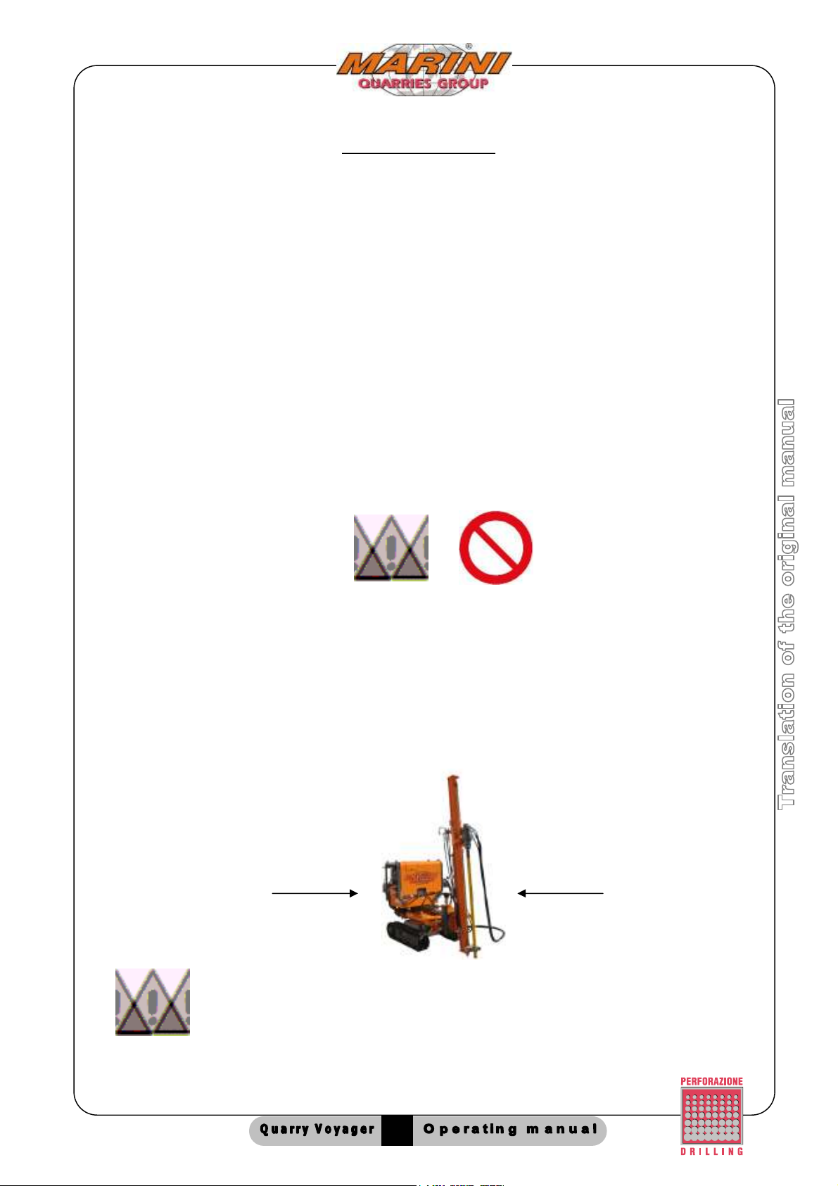
MANDATORY MACHINE DOWNTIME: If there is the risk that the defect could
compromise safety or cause further damage, the machine must not be used
until it has been repaired and tested.
Modifications to the machine
Marini Quarries Group reserves the right to make any necessary changes to its machines for any
technical or commercial needs without forewarning.
Identification of replacement parts
When requesting replacement parts, always indicate the machine’s serial number, found on the
chart on page 5, along with the required part, found on the attached spare parts lists.

072010
8
Identification of the machine:
The machine is identified by a serial number printed on the identification plate fixed to the
frame.
Furthermore, the engine, compressor and remote control have their own printed serial
numbers. To ensure fast and efficient service, the main serial numbers should be entered in
the table below.
When ordering replacement parts or for any technical information, always specify the data
reported in the following table:
TABLE OF IDENTIFICATION DATA
TABLE OF IDENTIFICATION DATATABLE OF IDENTIFICATION DATA
TABLE OF IDENTIFICATION DATA
Model:
QUARRY VOYAGER
Serial number:
052011
Year of manufacture:
2011
Rock drill type:
/
Type of rotary head:
ID 160
Track type:
G1,5 - 10
Hydraulic power unit type: Gasoline
Gasoline Gasoline
Gasoline –
––
– LOMBARDINI LD12 477(23 Hp)
LOMBARDINI LD12 477(23 Hp) LOMBARDINI LD12 477(23 Hp)
LOMBARDINI LD12 477(23 Hp)
Hydraulic column type:
CID 80
Figure 2
Identification plate
QUARRIES GROUP
MODEL
SERIAL NUMBER
DATE OF MANUFACTURING
ATTACHMENT WEIGHT
MAXIMUM OIL OPERATING PRESSURE
MAXIMUM OIL FLOW RATE
OIL TYPE
MAXIMUM AIR OPERATING PRESSURE
MAXIMUM AIR CONSUMPTION
MAXIMUM OPERATING TEMPERATURE
DRILL FLUSHING AIR / WATER

072010
9
2
3
4
5
6
Figure 3
1
TECHNICAL DESCRIPTION
QUARRY VOYAGER drilling unit:
The machine is fitted with quick connectors for separating:
•Self-moving carriage on tracks
•Drilling slide
•Control panel
•Hydraulic power unit
Is possible reconnecting them with extension hoses in order to reach difficult work positions.
1. Self-moving carriage on tracks
2. Hydraulic power unit with electric motor/internal combustion
engine
3. control panel for machine POSITIONING
4. WORK control panel (drilling)
5. hydraulic slide for the rock drill / rotary head
6. Rock drill / hydraulic rotary head (DTH or coring )

072010
10
The standard QUARRY VOYAGER drilling unit is composed of:
-Self-moving carriage on tracks
-CID 80 hydraulic drilling slide for the rock drill / rotary head
-Hydraulic power unit with internal-combustion engine
Optional accessories: Coring, Rotary head ID160, MA90 Rock Drill, Hydraulic vice, Rod guide,
Stabilizer, Drill steels, Threaded drifter rods, Drill steel sharpener, Handles and drill bits, Device
for drilling in water, Dust collector.
POSITIONING for VERTICAL drilling:
45°
30°
600 mm
400 mm
250°
POSITIONING for HORIZONTAL drilling:
Figure 4
MAX. 800mm
MIN. 30mm
MIN. 100mm
CON GUIDA ASTE:
MIN. 250mm
CON GUIDA ASTE E MORSA IDRAULICA:
Figure 5
WITH ROD GUIDE
WITH ROD GUIDE AND HYDRAULIC VICE

072010
11
TECHNICAL CHARACTERISTICS
SLIDE CID 80
High strength continuous link chain
Standard stroke : 1600 mm
(other strokes available upon request)
Thrust force : from 0 - 900 kg
Lifting force: 1000 kg
Slide feed cylinder : stroke 600 mm
Weight slide with stroke
of 1600 mm: 100 kg
HYDRAULIC POWER UNIT
12 HP electric motor, 400V AC, 50 Hz (ONLY VERSION WITH ELECTRIC MOTOR)
23 HP internal-combustion engine (ONLY VERSION WITH GASOLINE ENGINE)
Hydraulic fluid: MOBIL DTE 25 or equivalent
Calibration of the pressure relief valves (inside the power unit)
•discharge for rotary head : 200 bar
•discharge for feed cylinder and other services : 200 bar
CONTROL PANEL
Rotation distributor calibration : 140 bar
Advancement distributor calibration : 140 bar
Line lubricator with 7 liter reservoir
Oil for the line lubricator : MOBIL ALMO 525 or equivalent
Weight : 40 kg
Rock drill MA90 drilling and flushing air pressure : 6 bar (max)
DTH drilling and flushing air pressure : 10 bar (max)
NOTE: All the data on this sheet is approximate and non binding, in that Marini
Quarries reserves the right to make any modifications or changes ithout
fore arning.
2100
2300
1100
Figure 7

072010
12
MOVING AND TRANSPORT
CAUTION: The moving and transport of the machine must be done by
properly trained or specialized personnel.
Column weight CID-80 100 kg
Weight of self-moving carriage 850 kg
Hydraulic power unit weight (gasoline motor) 150 kg
Hydraulic power unit weight (diesel motor) 280 kg
Hydraulic power unit weight (electrical motor) 200 kg
Weight of rock drill MA90 29 kg
Weight of rotary head ID160 35 kg
Weight of coring IDCD 22 kg
LIFTING:
Position the machine as shown in the figure and
use special lifting hooks (G).
WARNING: to lift the machine
use No. 4 ropes with loading
capacity of 1000 kg each.
Marini Quarries Group ill assume no
Marini Quarries Group ill assume no Marini Quarries Group ill assume no
Marini Quarries Group ill assume no
responsibility for damage due to
responsibility for damage due to responsibility for damage due to
responsibility for damage due to
inappropriate use o
inappropriate use oinappropriate use o
inappropriate use of the machine.
f the machine.f the machine.
f the machine.
MACHINE WEIGHT CHANGE
ACCORDINLGLY WITH THE MODEL
AND ACCESSORIES
STANDARD MACHINE : 1300 Kg ca
THE MACHINE WEIGHT IS
PRINT ON THE PLATE one
QUARRIES GROUP
MODEL
SERIAL NUMBER
DATE OF MANUFACTURING
ATTACHMENT WEIGHT
MAXIMUM OIL OPERATING PRESSURE
MAXIMUM OIL FLOW RATE
OIL TYPE
MAXIMUM AIR OPERATING PRESSURE
MAXIMUM AIR CONSUMPTION
MAXIMUM OPERATING TEMPERATURE
DRILL FLUSHING AIR / WATER
2100
2300
1100
G
Figure 7
G

072010
13
Rotopercussion Pneumatic Rock Drill MA90
TECHNICAL DATA
Weight: 30kg
Total length: 565 mm
Sleeve bushing size: 22x108 mm (upon request 25x108 mm)
Piston diameter: 90 mm
Piston stroke: 50 mm.
Max working pressure 6 bar
Average air consumption at 6 bar: 4500 Litres/min (158 c.f.m.) with air vent
Average air consumption at 6 bar: 4000 Litres/min (140 c.f.m.) with water drain
Average water consumption at 2 bar: 5 Litres/min (1.3 US gal/min)
Impact rate per minute (6 bar): 2500
Blow force (6 bar) : 180 J
Impact power: 8 kW
Number of revolutions: 190 rev./min.
Figure 8

072010
14
ID 160 Rotary head
TECHNICAL DATA
Weight kg 35
Torque
Rotation torque at 140 bar Kgm 160
Working pressure bar 140∼160
Speed rpm 40∼45
Threading of the output shaft API 2”3/8 F
NOTE: The ID160 rotary head is interchangeable with the coring IDCD unit mounted on our
hydraulic drilling slides.
Coring ID CD
TECHNICAL DATA
Weight kg 22
Torque
Rotation torque at 140 bar Kgm 3,5
Working pressure bar 140∼160
Speed rpm 1100∼1300
Threading of the output shaft 1 ¼” W PIN
NOTE: The Coring IDCD is interchangeable with the ID160 rotary head mounted on our
hydraulic drilling slides.
SAFETY
Figure 10
Figure 9

072010
15
General information regarding safety
In the design and building of this machine, the criteria and procedures to meet the basic safety requirements foreseen by
European directive 2006/42/CE
In particular, measures were taken during the design and construction phase in order to prevent risks to the operators.
All the documentation regarding the adopted safety measures is contained in the technical file located at the offices of
Marini Quarries Group Srl.
For certain risks, solutions could not be found from a design point of view. In these cases, the safety measures to be
followed in order to operate as safely as possible are reported.
CAUTION: Marini Quarries Group recommends that the instructions,
procedures and recommendations provided in this manual be follo ed, that
all the suggested precautions for good technique be adopted and that the
current safety regulations be observed.
Safety rules
- The installation, maintenance and use of the machine is reserved for specialized personnel only.
- Make sure that the power supply has been shut off before performing any cleaning or maintenance interventions.
- Do not remove the machine guards that protect the moving parts.
- Do not place your hands inside parts where there is the risk of crushing and/or entanglement.
- During the work and positioning operations, the operator must stay at a safe distance with the remote control, in as
protected a position as possible.
- The lifting and transport of the machine as well as the handling of parts of the machine must be done with the machine
off by specialized personnel using suitable equipment.
- If machine components need to be replaced, use only original replacement parts.
Risks determined through analysis of the dangers and hazardous situations while working
Contact with overhead electrical lines, impacts, beating, compressions, vibrations, slipping, falling, noise, shearing,
grinding, falling of material from above, mineral oil and derivatives, remote controlled mechanical moving parts, safe
distances.
CAUTION
IT IS FORBIDDEN TO TOUCH EITHER THE HAMMER
OR THE RODS DURING DRILLING
OPERATIONSENTANGLEMENT AND CRUSHING RISK

072010
16
Safety decals
Safety decals and their locations:
Safety devices:
Figure (A) – Located on the frame of the
drilling carriage:
-
Danger: Live electrical components.
Risk of electrocution.
-
Danger: Crushing, shearing, vibrations,
compressions, pounding, grinding,
falling
of material from above, noise during
machine use.
- Danger: Possibility of being burnt
Figure (B) –
Located on the control
panels:
-
Danger: Read the operating and
maintenance manual before performing
any drilling or maintenance oper
ations on
the machine.
Figure (C) –
Located on the frame of the
drilling carriage.
Danger:
Read the operating and
maintenance manual before performing
any drilling or maintenance operations on
the machine.
Figure (D) – Located o
n the frame of the
drilling carriage:
Danger: Maintain a safe distance during
carriage movements and when drilling.
Figure (A)
Figure (D)
Figure (C)
Figure (B)

072010
17
The machine is outfitted with certain safety devices that
protect the user from incorrect maneuvers or in the case
of emergency.
Their locations and purposes:
Drive wheels with normal braking (POS 1): The
brake automatically releases both tracks when the
carriage movement levers are moved. The brake
remains engaged whether the engine is on and off.
The brake is immediately re-engaged when the
carriage movement levers are released.
Emergency stop cable (POS 2): When this is pressed,
all the machine actions are immediately stopped and
the motor of the power unit shuts off.
To restart the work, the cable must be reset by pulling
the button (E), figure 12 and reactivating the safety unit
by pressing one of the green buttons (S) on the control
panels, figure 12
The motor on the power unit can then be restarted.
Stop valves on the column positioning cylinders (POS 3):
They keep the cylinders locked in position in case of a
broken tube or lack of pressure in the hydraulic circuit.
POS. 1
POS. 3
POS. 2
Figure 11
POS. 4
Figure 12
E
Control
panel Control
panel
S
S
S = reset push button for emergency devices installed
on petrol motor. On the electric and diesel power pack
the emergency devices reset is automatic pushing the
motor start up button
Figure 13
POS. 3

072010
18
Pressure switch and safety solenoid valve on the air line coming from the
compressor:
(Optional – available only with the machine equipped with MA90 rock drill)
The safety solenoid valve (available on request) (G) on the air line allows the
compressed air to pass if the line pressure is at least 2-3 bar. If the compressor
malfunctions or is damaged, the pressure switch (K) closes the valve blocking the
machine movements and shutting down the motor on the power unit, Figure 14.
To restart the work, the cause of the compressor problem must be resolved. The safety
device interlock must then be reactivated by pressing one of the green buttons (S) on
the control panels.
Emergency stop buttons:
WORK control panel
S
G
Air inlet
pipe
K
Figure 14
S = reset push button for emergency devices installed on petrol motor. On the electric
and diesel
power pack the emergency devices reset is automatic pushing the motor start up button
Table of contents
Popular Industrial Equipment manuals by other brands

ChocoMa
ChocoMa 2T70 operating manual

Julabo
Julabo SW22 operating manual

Woodward
Woodward VariStroke-DX Component Maintenance Manual

Keysight Technologies
Keysight Technologies 16194A Operation and service manual

hager
hager univers N Mounting instructions

R.V.R. Elettronica
R.V.R. Elettronica TEX150 user manual