4
1. INTRODUCTION
1.1. PRECAUTIONS, REQUIREMENTS, RECOMMENDATIONS
Detailed analysis of this documentation, as well as assembly and use of equipment, according to the descriptions contained therein, and following all safety requirements, is the basis for the
correct and safe operation of the device. Any other use that contradicts this instruction may cause accidents with serious consequences. Unauthorised personnel should have limited access
to the device, while the personnel should be properly trained. The term operational personnel refers to people, who, as the result of completed training, own experience and knowledge of
important standards, documentation and provisions, concerning safety and working conditions, have been authorised to carry out necessary work and are able to recognise potential hazards
and avoid them. This technical documentation must be delivered together with the device. The documentation contains information concerning all possible congurations of air curtains.
Examples of air curtain assembly and installation, as well as activation, use, repair and maintenance. Provided that the device is operated according to the intended use, this documentation
contains a sucient number of instructions, required by the qualied personnel. The documentation should be placed near the device and be readily available to the service team. The
manufacturer reserves the right to introduce changes to the instruction, as well as changes to the device that aect its operation, without prior notice. Mark Climate Technology shall bear
no responsibility for on-going maintenance, inspections, programming of equipment and damage, caused by standstills of equipment related to the waiting for warranty services, all and any
damage related to the Client’s property, other than the device in question, as well as malfunctions that result from incorrect installation or improper use of the device.
EASYAIR air curtains are intended for indoor assembly only.
DO NOT COVER
WARNING: To avoid overheating - do not cover the device!
1.2. TRANSPORT
Prior to the installing and taking the device out of the cardboard box, it is required to check whether the cardboard box has not been damaged in any way and/or the adhesive tape (installed
at the company) has not been broken o or cut. It is recommended to check whether the device’s casing has not been damaged in transport. Should any of the above situation occur, please
contact
us
through
telephone
or
e-mail:
T
el.
+31
598
656
600,
email:
[email protected].
The device should be transported by two people. Use appropriate tools, when transporting the device, so as to avoid the damaging of goods and potential hazard to health.
1.3. INITIAL STEPS TAKEN BEFORE THE INSTALLATION
Record the serial number of the device in the warranty card, prior to the commencement of the installation process. It is required to properly ll-in the warranty card, after the completion of the
assembly. Prior to the commencing of any installation or maintenance work, it is required to disconnect power supply and protect it against unintentional activation.
Assembly, connection and rst start should be performed by qualied personnel, according to the guidelines provided in this manual.
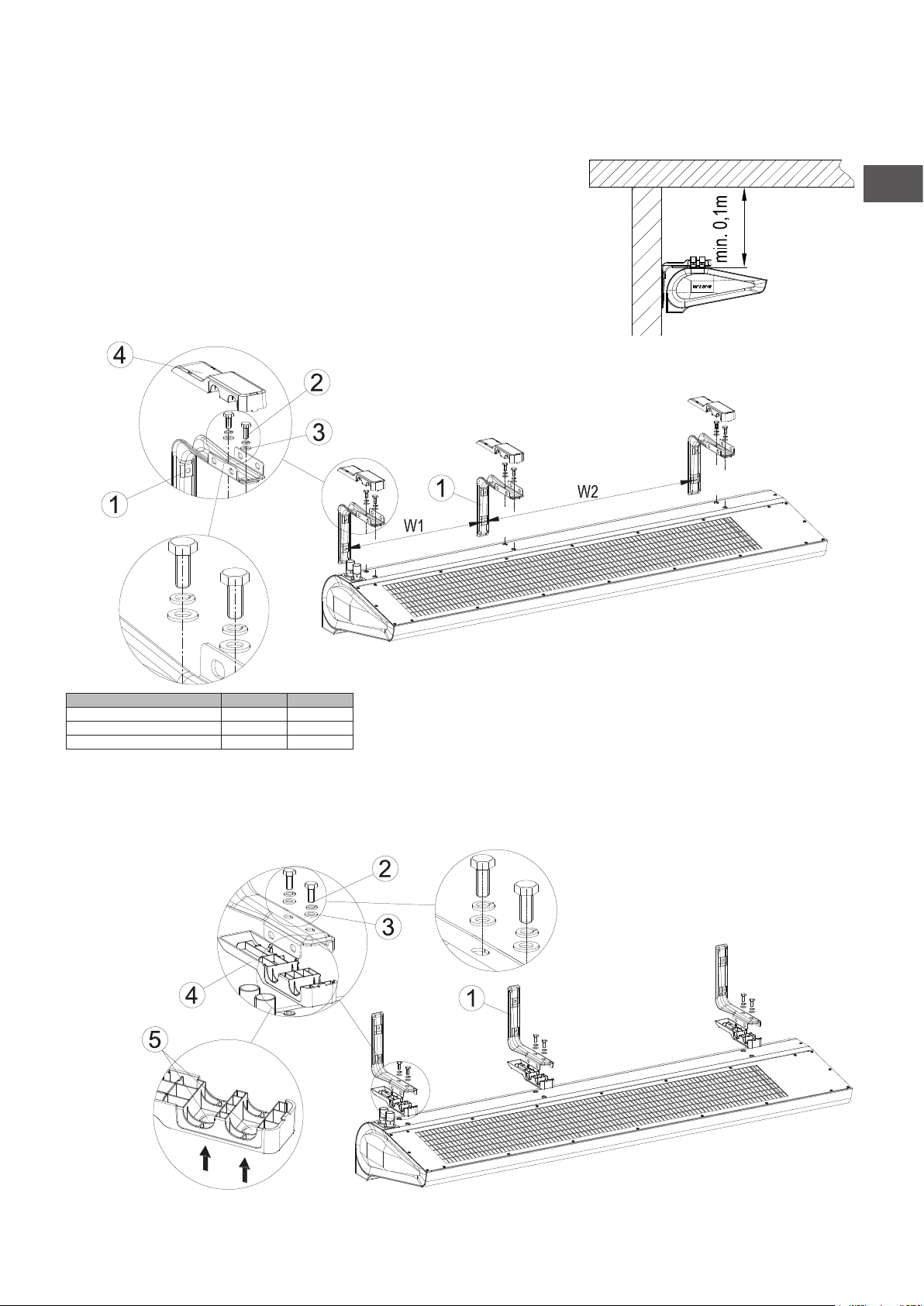
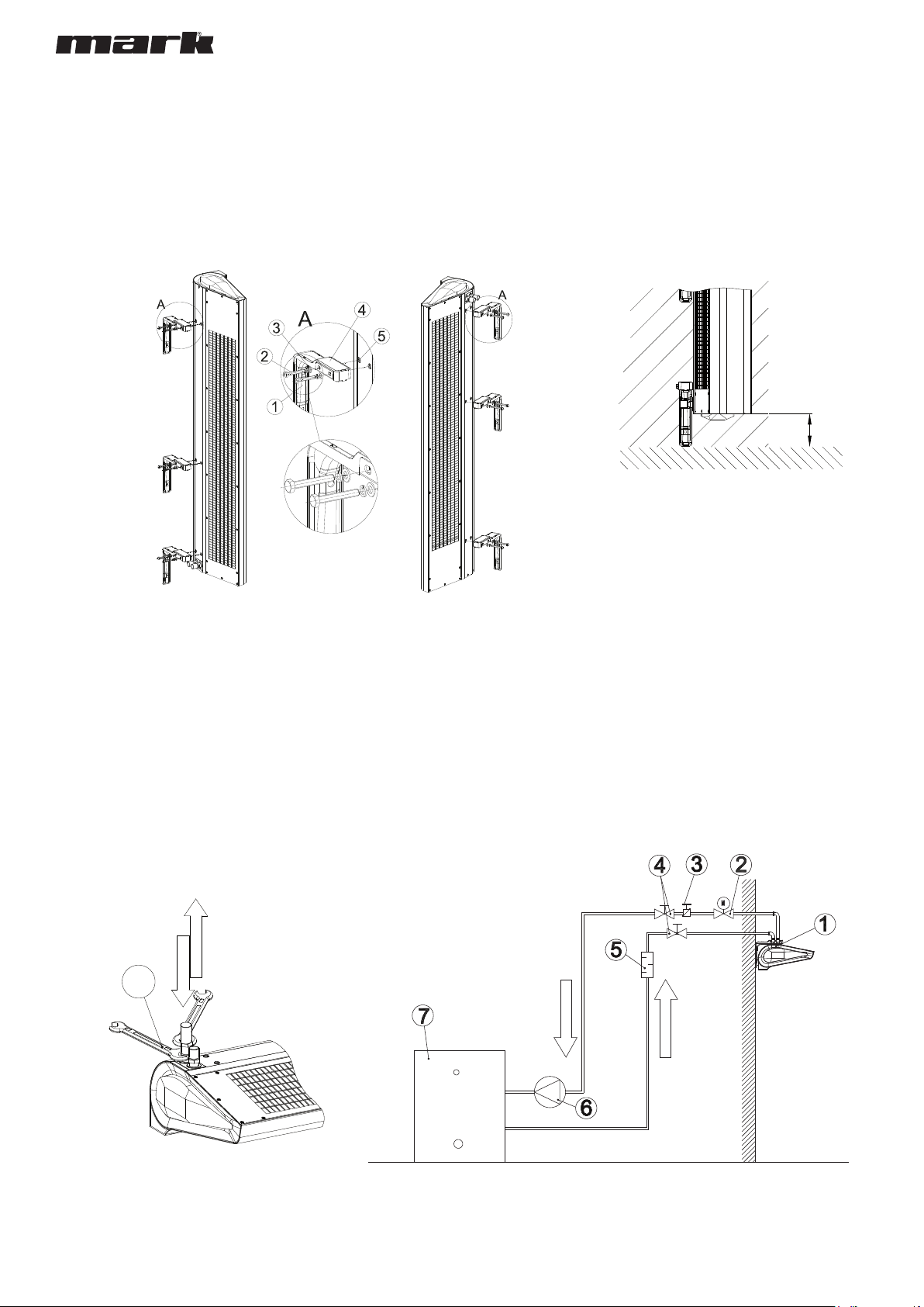
The order of installation steps:
• Mount the device in its intended operation place
• Perform the hydraulic connection, check connections for tightness and vent the system
• Perform the electrical connection
• Before attempting any installation works, ensure that EASYAIR air curtain (being a power supply source for the controller) is mechanically disconnected from electric power supply.
• Make sure the device is correctly connected (according to the diagram found in the back of this manual)
• In the case of an electrical curtain, vacuum the heaters to avoid the unpleasant smell of burning dust
• Turn the power on and start the device.
2. STRUCTURE, INTENDED USE, PRINCIPLE OF OPERATION
2.1. INTENDED USE
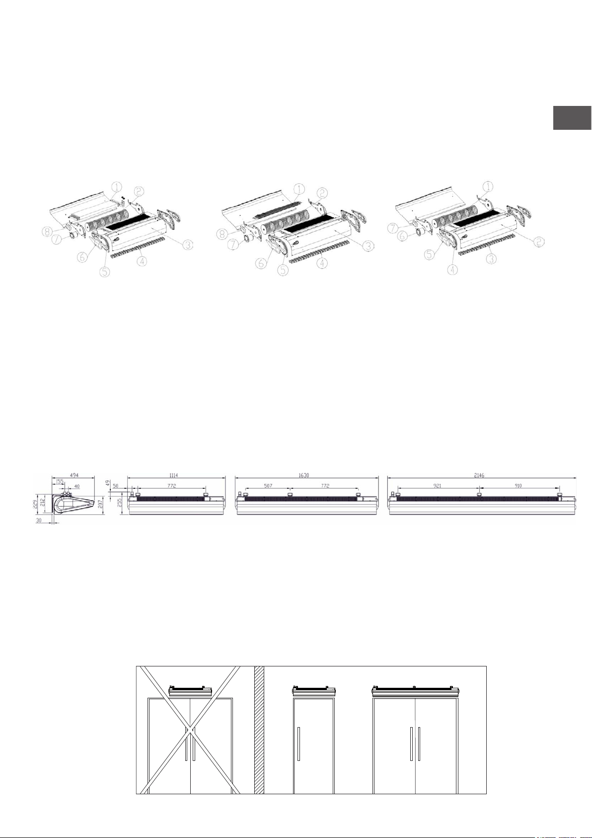
For the convenience of users as well as dierent types of installations in commercial and industrial facilities we have designed an air curtain in three dierent options and three sizes:
● EASYAIR W100 EC curtains 1.0m wide with a water heater ((4-17 kW, 1850 m³/h)
● EASYAIR E100 EC curtains 1.0m wide with electric heaters (2/4/6 kW, 1850 m³/h)
● EASYAIR C100 EC curtains 1.0m wide (1880 m³/h)
● EASYAIR W150 EC curtains 1.5m wide with a water heater (10- 32 kW, 3100 m³/h)
● EASYAIR E150 EC curtains 1.5m wide with electric heaters (8/12 kW, 3100 m³/h)
● EASYAIR C150 EC curtains 1.5m wide (3200 m³/h)
● EASYAIR W200 EC curtains 2.0m wide with a water heater (17- 47 kW, 4400 m³/h)
● EASYAIR E200 EC curtains 2.0m wide with electric heaters (5/15 kW, 4500 m³/h)
● EASYAIR C200 EC curtains 2.0m wide (4600 m³/h)
The use of the EASYAIR air curtain enables the leaving of the room door open, regardless of weather conditions, thus providing a protective barrier. The curtain also enables a simultaneous
keeping of the required heating comfort inside the room/facility. The modern design of the EASYAIR air curtain is a result of its wide range of application. The places in which it is possible to
install the device include: malls, oce buildings, supermarkets, cinema complexes, as well as shops, store-rooms, manufacturing facilities or warehouse rooms. Please notice that the use of an
air curtain not only provides a protective barrier, but also it is an additional heat source in the room. APPLICATION: warehouse rooms, warehouses, sports facilities,
supermarkets, religious buildings, hotels, clinics, pharmacies, hospitals, oce buildings, manufacturing facilities. PRIMARY ADVANTAGES: protection of climatic conditions in the room,
reduction of heating/cooling costs, universal size, ability to work both in vertical and horizontal position; simple, quick and intuitive assembly.
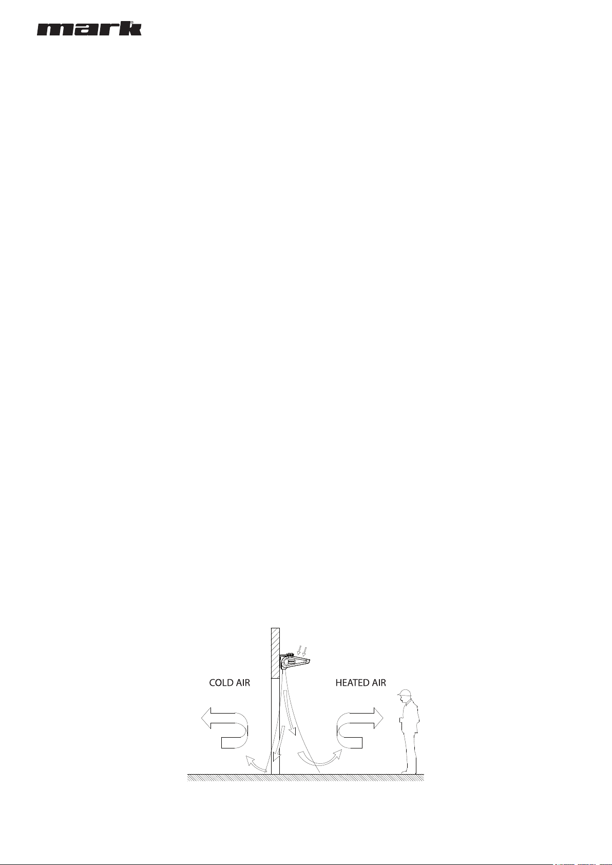
2.2. PRINCIPLE OF OPERATION
EASYAIR W100-200 - heating medium, for example hot heating water, returns heat through a heat exchanger with a wide heat-exchange surface, thus providing high heating output (4-47 kW).
A transverse fan (880-4400 m³/h) sucks in the air in the room, and pumps it through the heat exchanger, back into the room. The jet of warm air is directed downstream at high velocity, thus
providing an air barrier.
EASYAIR E100-200 - electric heaters (4-15 kW) heat up, as a result of the owing of electric current, and return the heat to the air; the air is blown o through the fan, which sucks in the air in
the room. A jet of warm air is directed downstream at high velocity, thus providing an air barrier.