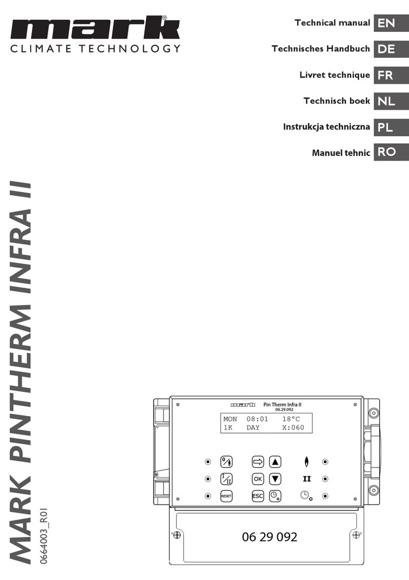
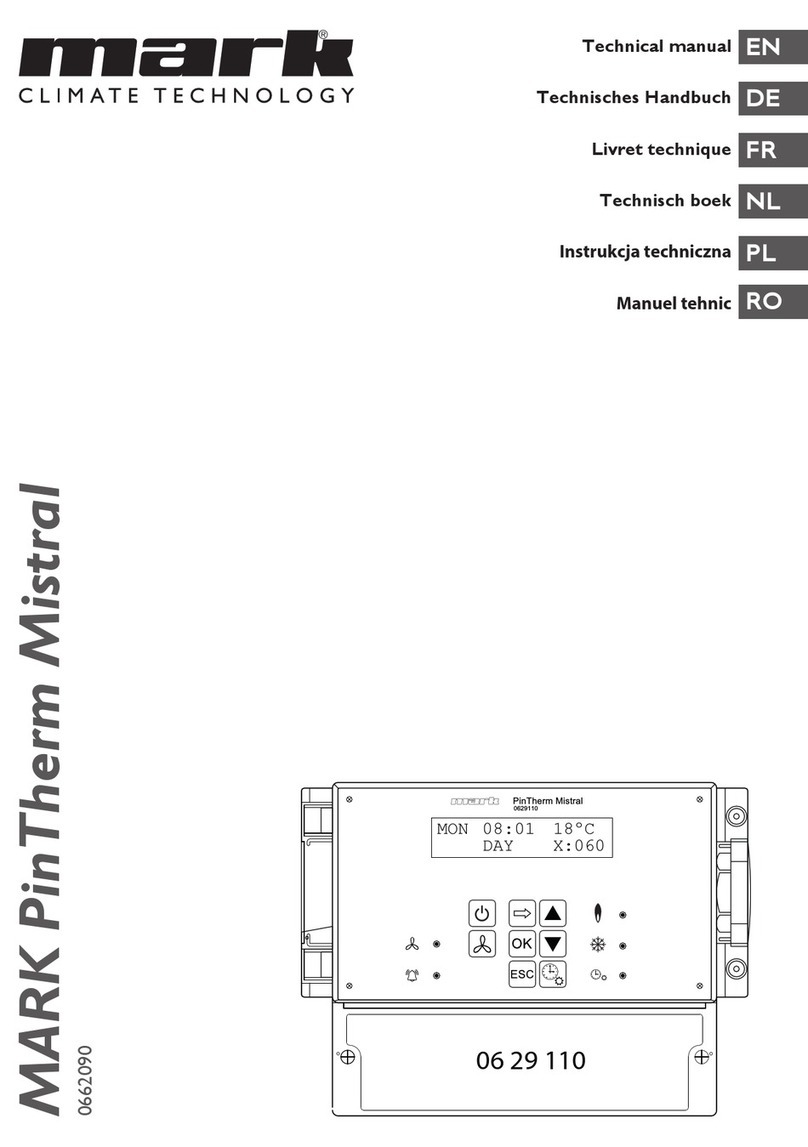
Mark Pin Therm+ 06 29 089 User manual

T chnical manual
T chnisch s handbuch
Livr t t chniqu
T chnisch bo k
Instruk ja te hni zna
EN
DE
FR
NL
PL
MARK PIN THERM+
06 64 002
OK
RESET ESC
0
0
06.29.089
Pin Therm+
06 29 089

2

Read this document before
installing the appliance
Warning
ncorrect installation, adjustment, alteration, repair or maintenance work may lead to material
damage or injury. All work must be carried out by certified, qualified professionals. f the appli-
ance is not positioned in accordance with the instructions, the warranty shall be rendered void.
This appliance is not intended for use by children or persons with a physical, sensory or mental
handicap, or who lack the required experience or expertise, unless they are supervised or have
been instructed in the use of the appliance by somebody who is responsible for their safety.
Children must be supervised to ensure that they do not play with the appliance.
1.0 Contents
1.0 Contents page 03
2.0 General
2.1 All rights reserved page 04
2.2 General warnings page 04
2.3 Reference to a table or illustration page 04
3.0 Te hni al spe ifi ations
3.1 Technical specifications, Pin Therm+ page 04
3.2 Technical details, external room sensor (optional) page 04
3.3 Resistance chart, (external) room sensor page 05
3.4 Default settings, Pin Therm+ page 05
4.0 Installation
4.1 General page 05
4.2 nstallation, Pin Therm+ page 05
4.3 nstallation, external room sensor (optional) page 06
5.0 Operating manual
5.1 Explanation of the push-buttons and LEDs page 07
5.2 Explanation of the display page 08
5.3 nitial operation of the Pin Therm+ page 08
5.4 Activate user menu page 09
5.5 Enter or change switching times page 09
5.6 Change day/night temperature setting page 10
5.7 Change time and date page 10
5.8 Change menu code page 10
5.9 Change language page 11
5.10 Calibration temperature page 11
5.11 Change minimum control signal. page 11
5.12 Change maximum control signal page 12
5.13 Change control signal range page 12
5.14 Switch overtime timer on/off page 12
5.15 Switch on chimney-sweep function page 13
5.16 Restore factory settings, Pin Therm+ page 13
6.0 Disposing of the Pin Therm+ page 13
7.0 Pin Therm+ onne tions page 14
Wiring diagrams page 15 3
EN

4
2.0 General
2.1 All rights reserved.
The manufacturer has a policy of continuous product improvement and reserves the right to make
changes to the specifications without prior notice. The technical details are considered correct
but do not form the basis for a contract or warranty. All orders are accepted subject to the stan-
dard terms and conditions of sale and delivery (which will be sent to you at your request).
2.2 General warnings.
nstallation must comply with the relevant local and/or national regulations. You must therefore
have the Pin Therm+ installed by a professionally qualified installer in accordance with all applica-
ble national and international regulations. Faulty installation, adjustment, alteration, maintenance
activity or repair shall render the warranty void.
2.3 Reference to a table or illustration.
f reference is made in the manual to an illustration or table, a number between square brackets is
used, e.g. [3]. The number refers to images and tables at the back of the manual with the stated
number.
3.0 Technical specifications
3.1 Technical specifications, Pin Therm+.
• Type designation : Pin Therm+
• tem number : 06 29 089
• Pin Therm+ power supply : 230 VAC / 50Hz
• Clock : 24-hour clock with automatic summer/winter time transition
• Switching differential : 1K
• Dimensions : 166 x 160 x 106mm (l x w x h)
• Weight : 880 grammes
• Protection class: : P 54
• Ambient temperature : 0-40
• Switching contact(s) : 230VAC/10(4)A
• Temperature setting : 0 to 39°C, in increments of 1°C
• Overwork timer : choice of 3 settings: 1, 2 or 3 hours (060, 120, 180)
• Calibration temp. : setting range from -3.5°C to +3.5°C
• Sensor : NTC4K7 room sensor in the Pin Therm+.
An external room sensor may be fitted (option).
• Language options : Dutch, English, German ,French, talian and Polish.
3.2 Technical details, external room sensor (optional):
• Type designation : RTF1 NTC4,7K
• tem number : 06 29 086
• Resistance : NTC 4K7
• Dimensions : 79 x 81 x 26mm (l x w x h)
• Weight : 42 grammes
• Electrical connection : 0.75 -1.5mm²
• Protection class : P 30

EN
5
3.3 Resistance chart, (external) room sensor.
-15°C -10°C -5°C 0°C 5°C 10°C 15°C
32,937kW 25,217kW 19,392kW 15,040kW 11,743kW 9,241kW 7,330kW
20°C 25°C 30°C 35°C 40°C 45°C 50°C
5,855kW 4,700kW 3,777kW 3,071kW 2,512kW 2,066kW 1,.709kW
3.4 Default settings, Pin Therm+.
• Menu code : 1000
• Switching times : MON, TUE, WED, THU, FR 07.30-17.30 hours
SAT, SUN 00.00-00.00 hours
• Room temperature : Day setting 18°C
Night setting 08°C
• Calibration temp. : +0.0
• 0-10V min(0-5V) : 2.0 V
• 0-10V max(5-10V) : 10.0 V
• 0-10V Range(1-3) : 1.0
4.0 Installation
4.1 General.
After unpacking the Pin Therm+, check the external room sensor supplied with the unit for dam-
age (if applicable). Check that the type/model and the rated voltage are correct.
4.2 Installation, Pin Therm+.
Determine a suitable place for installing the Pin Therm+. The internal room sensor is mounted in-
side the Pin Therm+ and the Pin Therm+ should therefore be installed in the space/room that is
to be heated. This does not apply if the optional external room sensor is to be used.
We recommend mounting the Pin Therm+ at a height of ±1.5m from the floor.
Check that the power supply has been switched off before connecting any wiring. f this is not the
case, the power supply must be switched off before you continue. When switching off the power
supply of the appliance to which connection is to be made, you should also refer to the technical
documentation/operating instructions for the appliance in question.
Connect the 0-10VDC signal from the Pin Therm+ to the air heater in accordance with one of the
two diagrams at the back of the technical documentation. Refer to the chart below for the correct
wire diameter and length. [1] [2]
Diameter Length
0.8mm² 125 metres
mn this case, we advise the use of a shielded cable.
the use of a shielded cable.
1.0mm² 150 metres
1.5mm² 250 metres

6
4.3 Installation, external room sensor (optional).
As standard, the Pin Therm+ is equipped with an on-board temperature sensor. t is also possible
to use an optional external room sensor. f an external sensor is used, the internal room sensor is
automatically switched off.
Consideration must be given to the following when determining the right position for the external
sensor:
– not in direct sunlight
– not close to a heat source
– not on a non-insulated external wall
– not close to an outside door
– Choose a draught-free location at a height of approx. 1.5m from the floor.
Next, connect the sensor to the sensor terminals (1 + 2) in the Pin Therm+. Refer to the chart
below for the correct wire diameter and length.
Diameter Length
0.8mm² 125 metres
mn this case, we advise the use of a shielded cable.
the use of a shielded cable.
1.0mm² 100 meter
1.5mm² 150 meter

EN
7
5.0 Operating manual
5.1 Explanation of the push-buttons and LEDs.
A. - lluminated display (see also 5.2)
B. - Push-button for switching the heating mode on and off.
C. - LED, lit when the heating mode is active.
D. - Push-button for switching the ventilation mode on and off.
E. - LED, lit when the ventilation mode is active.
F. - Push-button for switching the appliance out of lock-out after a (burner) fault.
G. - LED, lit when a (burner) fault has been detected.
H. - Push-button for activating the user menu or to display the next value.
. - Push-button for confirming a selection/change or for displaying the next menu item.
J. - Push-button for exiting the setting or menu without executing a change.
K. - Push-button for switching the overtime timer on and off.
L. - Push-button +– to change a setting.
M. - LED, lit when there is heat demand in the heating mode (burner on).
N. - LED, lit when the fan is switched on.
O. - LED, lit when the overtime timer function is active.
5.2 Explanation of the display.
A. - ndicates the day of the week.
B. - The current clock time is shown here.
C. - ndicates the measured temperature (°C).
D. - ndicates the number of minutes before the overtime timer function is switched off again and
the Pin Therm+ will return to night temperature control mode.
E. - ndicates whether the Pin Therm+ is set to daytime mode (DAY) or to night mode (N GHT)
and temperature control based on the daytime or night temperature setting.
A16°C
X:060
MON
DAY
08:01
E
B
C
D
C
OK
RESET ESC
0
E
G
M
N
O
D
F
JK LI
A
B
H
0
MON
DAY
08:01
X:060
16°C
06.29.089
Pin Therm+

5.3 Initial operation of the Pin Therm+.
When you connect a power supply to the Pin Therm+ for the first time, you will be asked to se-
lect your choice of language, (language settings: Dutch, English, German, French, talian and Polish.)
Having done so, the next step is to set the time and date. After the time and date have been set,
the Pin Therm+ displays the main screen and activates the “heating” function.
Language options: Dutch, English, German ,French, talian and Polish.
5.4 Activate user menu.
You can change the following settings in the menu:
– Enter/change switching times
– Change day/night setting
– Change time/date
– Change menu code
– Change language
– Calibration
– 0-10V min (0-5V)
– 0-10V max (5-10V)
– 0-10V range (1-3)
ENTER CODE
exit the menu and return
to the main screen
Factory setting menu
code
1000
°CMon
DAy
08:01 16
changes the
ashing value
go to the
next value
select your choice
of menu option
ESC
OK OK
0000
ENTER/CHANGE
SWITCHING TIMES
SELECT LANGUAGE SAT 01-01-2006
00:00:00
°CMON
DAY
08:00 16
chnges the
ashing value
go to the
next value
select language
OK OK
ENGLISH
8

5.5 Enter or change switching times.
5.6 Change day/night temperature setting.
5.7 Change time and date.
MON 23-03-2009
09:10:00
select OK OK
CHANGE
TIME/DATE
changes the
ashing value
go to the
next value
back to
the menu
18°C
DAY SETTING
NIGHT SETTING
select OK OK
OK
08°C
SET/CHANGE
TEMPERATURE
changes the
ashing value
changes the
ashing value
go to the
next value
go to the
next value
back to
the menu
MONDAY
TUESDAY etc. SUNDAY
back to
the menu
changes the
ashing value
changes the
ashing value
go to the
next value
go to the
next value
OK OK
OK
07:30-->17:00
07:30-->17:0007:30-->17:00
ENTER/CHANGE
SWITCHING TIMES
9
EN

10
5.8 Change menu code.
5.9 Change language.
Language options: Dutch, English, German, French, talian and Polish.
5.10Calibration temperature
f the Pin Therm+ is installed in an unfavourable position, the actual temperature and the tempera-
ture measured by the Pin Therm+ may differ. This temperature difference can be compensated by
setting a correction factor in this temperature calibration function. f this solution is inadequate,
you also have the option of connecting an external room sensor to the Pin Therm+.
For example: The measured temperature is 18°C, but the Pin Therm+ display indicates
20°C. The difference in this example is 2°C too high the correction value
must be set to -2°C.
CALIB TEMP CALIB TEMP
Correction value can be set in the range
select OK OK
+ 0.0°C
from -3,5°C tot +3,5°C
changes the
ashing value
go to the
next value
back to
the menu
NEDERLANDS
SELECT LANGUAGE
select
language
select OK OK
SELECT
LANGUAGE
back to
the menu
SELECT NEW CODE
New menu code
SELECT OK OK
1000
CHANGE MENU
CODE
changes the
ashing value
go to the
next value
back to
the menu

5.11Change minimum control signal.
Note:
When there is no demand for heat, the Pin Therm+ sends out a signal of 0VDC.
5.12Change maximum control signal.
5.13 Change control signal range.
This function determines when the 0 – 10VDC signal is modulated back in conditions of heat de-
mand. When set to 1.0, the Pin Therm+ will start to modulate the 0 - 10V signal at 1K below the
target temperature.
The range can be set between 0.5 – 3.0 and is set to 1.0 as standard.
back to
the menu
select
change setting
OK OK
0-10V Range(1-3)
1.0
0-10V Range(1-3)
select
change setting
OK OK
0-10V min(0-5V)
2.0 V
0-10V min(0-5V)
back to
the menu
select
change setting
OK OK
0-10V max(5-10V)
10.0 V
0-10V max(5-10V)
back to
the menu
EN
11

5.14 Switch overtime timer on/off.
This function provides the option of manually switching to the daytime temperature outside the
set switching times for a period of 1, 2 or 3 hours.
The yellow LED with the symbol is lit when this function is active. n addition, the bottom right of
the display shows the time in minutes that still remains before the function is deactivated and the
Pin Therm+ returns to night temperature control. The function can also be switched off prema-
turely by pressing the push-button again until the yellow LED extinguishes and the number of re-
maining minutes disappears from the display. See the illustration below.
5.15 Switch on chimney-sweep function.
You can use this function to switch the appliance temporarily to full heat output/partial heat out-
put so that measurements can be taken. Refer to the information below for instructions on how
to switch this function on and off. After activation, this function remains switched on for 15 min-
utes and will switch off automatically again after that period..
5.16 Restore factory settings, Pin Therm+.
All the factory settings are restored when you activate this function. This function may be acti-
vated at any time. See the illustration below.
NIGHT
MON 17:01 °C
X:060
MON
DAY
17:01 18
X:120
MON
DAY
17:01
X:180
MON
DAY
17:01 18 °C18 °C
18 °C
SELECT LANGUAGE
°CMON
DAY
08:01 16
Press and hold down
for ±12 seconds
OK OK
ESC
ENGLISH
DEFAULT SETTINGS
RESTORED!
RESET TO DEFAULT
SETTINGS?
This takes you back to the
main screen without restoring
the factory settings!
This switches the function off and takes you back
to the main screen
ESC
0-10V
10V
14:59
press to increase the voltage (maximum of 10V)
Use the push-buttons referred to below to have the
appliance run at a lower voltage (reduce the heat output)
press to lower the voltage
Press and hold down
for ±12 seconds
0
12

OK
RESET ESC
0
0
06.29.089
Pin Therm+
MA
DAG
08:01
X:060
18°C
PE NL -+ DEFAB21
21
PE NL
AB
-+
DEF
6.0 Disposing of the Pin Therm+.
When the Pin Therm+ is replaced or removed, it must be recycled or destroyed in accordance
with national and/or local legislation and regulations.
7.0 Pin Therm+ connections
- Connection terminals for the (optional) external sensor.
- Power supply terminals for the Pin Therm+.
(230 VAC/50Hz)
- Connection terminals for the 0-10VDC control signal to the air heater.
- Reset and fault signal.
D- Fault light
E- Reset contact
F- Common
- Connection terminals for switching on the air heater fan.
13
EN

14
.[1]
[2]
LPN
FA BCDE FUSE
6.3A
E
G(S)+
MARK Pin Therm+ 06 29 089
PENL DEFAB12-+
-+
0-10Vdc
230Vac/50Hz
NLPE
WS
16A
V
12
06 29 086
TT Rx
6A
WS
230Vac/50Hz
NLPE
230Vac
0-10Vdc230Vac 230Vac
WW
10
TH-0629089-EU
1.020-12-2010J.W.
4
3
2
1
1
2
2
1
4
3
LPN
FA BCDE FUSE
6.3A
E
G(S)+
12
06 29 086
NLPE
TT
6A
WS
MARK Pin Therm+ 06 29 089
PE NL DEFAB12-+
-+ LPN
FA BCDE FUSE
6.3A
E
G(S)+
-+
+
-
230Vac/50Hz
NLPE
230Vac/50Hz
NLPE
WS WS
16A 16A
Max. 8
G(S)+
V
Rx
S1
30 02 002
230Vac
BOUTONDE
REARMEMENT
RESETKNOP
PRESSTO RESET
ENTRIEGELKNOPF
0550099
BOUTONDE
REARMEMENT
RESETKNOP
PRESSTO RESET
ENTRIEGELKNOPF
0550099
S1
30 02 002
230Vac
0-10Vdc 230Vac230Vac/50Hz 0-10Vdc 230Vac
0-10Vdc230Vac
WW
S1 TT W WS
Use a shielded cable for thisIlluminated reset button in the housing (230V) External room sensor (optional) Isolator switch
EN
20
TH-0629089-EU
1.020-12-2010J.W.
2
1
4
3
1
2
3
4
2
3
4
1
2

DE
Lesen Sie dieses Dokument sorgfältig
durch, bevor Sie das Gerät installieren
Warnhinweis
Fehlerhaft durchgeführte nstallationen, Einstellungen, Änderungen, Reparaturen oder War-
tungsmaßnahmen können zu Sachschäden und Verletzungen führen. Alle Arbeiten müssen von
geprüften, qualifizierten Fachleuten durchgeführt werden. Falls das Gerät nicht vorschriftsgemäß
aufgestellt wird, erlischt die Garantie. Dieses Gerät ist nicht für den Gebrauch durch Personen
(einschließlich Kindern) mit verminderter körperlicher, Sinnes- oder geistiger Leistungsfähigkeit
oder mangelnder Erfahrung und mangelnden Kenntnissen bestimmt, sofern sie nicht unter Auf-
sicht stehen oder durch eine Person, die für ihre Sicherheit verantwortlich ist, im Gebrauch des
Geräts angeleitet werden. Kinder müssen vom Gerät ferngehalten werden.
1.0 Inhalt
1.0 Inhalt Seite 03
2.0 Allgemein
2.1 Änderungen vorbehalten Seite 04
2.2 Allgemeine Warnhinweise Seite 04
2.3 Verweis auf Tabelle oder Abbildung. Seite 04
3.0 Te hnis he Daten
3.1 Technische Daten Pin Therm+ Seite 04
3.2 Technische Daten externer Raumfühler (optional) Seite 04
3.3 Widerstandstabelle (externer) Raumfühler Seite 05
3.4 Werkseinstellungen Pin Therm+ Seite 05
4.0 Montage
4.1 Allgemeines Seite 05
4.2 Montage der Pin Therm+ Seite 05
4.3 Montage eines externen Raumfühlers (optional) Seite 06
5.0 Bedienungsanleitung
5.1 Erläuterung der Drucktasten und LEDs Seite 07
5.2 Erläuterung des Displays Seite 08
5.3 Erste nbetriebnahme der Pin Therm+ Seite 08
5.4 Aktivierung des Benutzermenüs Seite 09
5.5 Schaltzeiten eingeben oder ändern Seite 09
5.6 Tages- und Nachttemperatur ändern Seite 10
5.7 Uhrzeit und Datum ändern Seite 10
5.8 Menücode ändern Seite 10
5.9 Sprachauswahl ändern Seite 11
5.10 Justierung Seite 11
5.11 Minimumregelsignal ändern. Seite 11
5.12 Minimumregelsignal ändern Seite 12
5.13 Bereich Minimumregelsignal ändern Seite 12
5.14 Überstundenzähler ein-/ausschalten Seite 12
5.15 Schornsteinfegerfunktion einschalten Seite 13
5.16 Werkseinstellungen des Pin Therm+ wiederherstellen+ Seite 13
6.0 Entsorgung des Pin Therm+ Seite 13
7.0 Ans hlussmögli hkeiten Pin Therm+ Seite 14
Ans hlusss hemata Seite 15
15

16
2.0 Allgemeines:
2.1 Änderungen vorbehalten.
Der Hersteller strebt eine kontinuierliche Verbesserung der Produkte an und behält sich das
Recht vor, ohne vorherige Mitteilung Änderungen an den technischen Daten vorzunehmen. Die
technischen Angaben werden als korrekt angenommen, bilden aber keine Grundlage für einen
Vertrag oder Gewährleistungsansprüche. Alle Bestellungen werden gemäß den Standardkonditio-
nen in unseren allgemeinen Verkaufs- und Lieferbedingungen angenommen (diese werden auf An-
frage zur Verfügung gestellt).
2.2 Allgemeine Warnhinweise.
Die nstallation muss den geltenden landesweiten und örtlichen Bestimmungen entsprechen.
Daher darf das Gerät nur von einem sachkundigen und qualifizierten nstallateur unter Beachtung
der nationalen und internationalen Vorschriften installiert werden. m Falle einer unsachgemäßen
nstallation, Einstellung, Änderung, Wartung oder nstandsetzung erlischt die Gewährleistung.
2.3 Verweis auf Tabelle oder Abbildung.
Wenn in der Anleitung auf eine Abbildung oder Tabelle verwiesen wird, wird eine Zahl in eckigen
Klammern angegeben, beispielsweise [3]. Die Zahl verweist auf die Abbildungen und Tabellen mit
der entsprechenden Nummer am Ende der Anleitung.
3.0 Technische Daten
3.1 Technische Daten Pin Therm+.
• Typbezeichnung : Pin Therm+
• Artikelnummer : 06 29 089
• Spannungsversorgung Pin Therm+ : 230 V Wechselstrom/50 Hz
• Uhr : Uhr mit 24-Stunden-Anzeige und automatischer
Umstellung von Sommer- und Winterzeit
• Schaltdifferenz : 1K
• Abmessungen : 166 x 160 x 106 mm (L x B x H)
• Gewicht : 880 g
• Schutzgrad : P-54
• Umgebungstemperatur : 0-40 °C
• Schaltkontakt(e) : 230 V Wechselstrom/10(4) A
• Temperatureinstellung : 0 bis 39 °C, in Schritten von 1° C einstellbar
• Überstundenzähler : einstellbar auf 1, 2 oder 3 Stunden (060, 120, 180)
• Justierung : einstellbar von -3,5 °C bis +3,5 °C
• Sensor : NTC4,7K Raumfühler im Pin Therm+.
Montage eines externen Raumfühlers ist möglich.
• Einstellbare Sprachen : Niederländisch, Englisch, Deutsch, Französisch,
talienisch und Polnisch.
3.2 Technische Daten externer Raumfühler (optional):
• Typbezeichnung : RTF1 NTC4,7K
• Artikelnummer : 06 29 086
• Widerstand : NTC 4K7
• Abmessungen : 79 x 81 x 26 mm (L x B x H)
• Gewicht : 42 g
• Elektrischer Anschluss : 0,75 - 1,5 mm²
• Schutzgrad : P-30

17
3.3 Widerstandstabelle (externer) Raumfühler.
-15°C -10°C -5°C 0°C 5°C 10°C 15°C
32,937kW 25,217kW 19,392kW 15,040kW 11,743kW 9,241kW 7,330kW
20°C 25°C 30°C 35°C 40°C 45°C 50°C
5,855kW 4,700kW 3,777kW 3,071kW 2,512kW 2,066kW 1,.709kW
3.4 Werkseinstellungen Pin Therm+.
• Menücode : 1000
• Schaltzeiten : MO, D , M , DO, FR 07.30-17.30 Uhr
SA, SO 00.00-00.00 Uhr
• Raumtemperatur : Tagestemperatur 18 °C
Nachttemperatur 8 °C
• Justierung : +0,0
• 0-10 V min(0-5 V) : 2,0 V
• 0-10 V max (5-10 V) : 10,0 V
• 0-10 V Bereich(1-3) : 1,0
4.0 Montage
4.1 Allgemeines.
Prüfen Sie nach dem Entpacken der Pin Therm+ und - falls bestellt - den mitgelieferten externen
Raumfühler auf Beschädigungen. Überprüfen Sie die Richtigkeit des gelieferten Typs/Models sowie
die elektrische Spannung.
4.2 Montage des Pin Therm+.
Legen Sie einen geeigneten Ort für den Einbau der Pin Therm+ fest. Der Temperaturfühler befin-
det sich in der Pin Therm+, weshalb die Pin Therm+ in dem zu heizenden Raum angebracht wer-
den muss. Dies gilt nicht, wenn der optionale externe Raumfühler verwendet wird.
Es wird empfohlen, die Pin Therm+ auf ± 1,5 m über dem Fußboden anzubringen.
Überprüfen Sie vor dem Anschließen der Verkabelung, ob die Spannung ausgeschaltet ist. Sollte
dies nicht der Fall sein, ist vor allen weiteren Schritten zuerst die Spannung auszuschalten. Beim
Ausschalten der Spannung, des anzuschließenden Geräts, ist hierbei ebenfalls das technische Hand-
buch/die Bedienungsanleitung des Geräts zu beachten.
Schließen Sie das 0-10 VDC-Signal des Pin Therm+ gemäß einem der beiden elektrischen Schalt-
schemen, die im hinteren Teil dieses technischen Handbuchs aufgeführt sind, an den Lufterhitzer
an. Siehe nachfolgende Tabelle für den richtigen Kabeldurchmesser und die richtige Länge. [1] [2]
Durchmesser Länge
0.8mm² 125 m
1.0mm² 150 m
1.5mm² 250 m mEs wird empfohlen, hierfür ein geschirmtes Kabel zu
verwenden.
DE

18
4.3 Montage eines externen Raumfühlers (optional).
Die Pin Therm+ ist standardmäßig mit einem eigenen Temperaturfühler ausgestattet. Als Option
gibt es die Möglichkeit, einen externen Raumfühler anzuschließen. Wenn dieser angeschlossen
wird, wird der interne Raumfühler automatisch ausgeschaltet.
Zur Festlegung eines geeigneten Anbringungsorts für den externen Fühler müssen nachfolgende
Punkte berücksichtigt werden:
– nicht der Sonne aussetzen
– nicht in der Nähe einer Wärmequelle
– nicht an einer nichtisolierten Außenwand
– nicht in der Nähe einer Flügeltür
– an einem zugfreien Ort anbringen, in einer Höhe von ca. 1,5 m über dem Fußboden.
Schließen Sie dann den Fühler an die dafür vorgesehenen Klemmen (1+2) im Pin Therm+ an. Siehe
nachfolgende Tabelle für den richtigen Kabeldurchmesser und die richtige Länge.
Durchmesser Länge
0.8mm² 125 m
1.0mm² 150 m
1.5mm² 250 m mEs wird empfohlen, hierfür ein geschirmtes Kabel zu
verwenden.

19
5.0 Bedienungsanleitung
5.1 Erläuterung der Drucktasten und LEDs.
A. - Beleuchtete Anzeige (siehe auch 5.2)
B. - Drucktaste zum Ein- oder Ausschalten der Erwärmungsstufe.
C. - LED leuchtet auf, wenn die Funktion Erwärmen eingeschaltet ist.
D. - Drucktaste zum Ein- und Ausschalten der Stellung Lüften.
E. - Die LED leuchtet auf, wenn die Lüftungsfunktion eingeschaltet ist.
F. - Drucktaste, um das Gerät im Fall einer (Brenner-)Störung zu entsperren.
G. - LED leuchtet im Fall einer (Brenner-)Störung
H. - Drucktaste, um das Benutzermenü zu aktivieren oder um zum nächsten Punkt zu gehen.
. - Drucktaste, um eine durchgeführte Wahl/Änderung zu bestätigen oder um zum näch-
sten Menüpunkt zu gehen.
J. - Drucktaste, um das Menü oder die Eiinstellung zu verlassen, ohne eine Änderung durch-
zuführen.
K. - Drucktaste, um den Überstundenzähler ein- oder auszuschalten.
L. - Schaltfläche +– um eine Einstellung zu ändern.
M. - LED leuchtet bei Wärmebedarf in der Stufe Erwärmen (Brenner ein) auf.
N. - Die LED leuchtet auf, wenn der Lüfter eingeschaltet ist.
O. - LED leuchtet auf, wenn die Funktion Überstundenzähler eingeschaltet ist.
5.2 Explanation of the display.
A. - Zeigt den Wochentag an.
B. - Zeigt die aktuelle Uhrzeit an.
C. - Zeigt die gemessene Temperatur (°C) an.
D. - Zeigt die Anzahl der Minuten an, bevor die Funktion Überstundenzähler wieder ausge-
schaltet wird und die Pin Therm+ in der Nachttemperaturstellung arbeitet.
E. - Zeigt an, ob die Pin Therm+ in der Tagesstellung (TAG) oder Nachtstellung (NACHT)
steht und in der Tag- oder Nachttemperaturstellung arbeitet.
A16°C
X:060
MA
TAG
08:01
E
B
C
D
C
OK
RESET ESC
0
E
G
M
N
O
D
F
JK LI
A
B
H
0
MA
TAG
08:01
X:060
16°C
06.29.089
Pin Therm+
DE

5.3 Erste Inbetriebnahme der Pin Therm+.
Wenn Sie die Pin Therm+ das erste Mal einschalten, werden Sie aufgefordert, die gewünschte
Sprache zu wählen (einstellbare Sprachen: Niederländisch, Englisch, Deutsch, Französisch, talie-
nisch und Polnisch). Anschließend müssen Sie Zeit und Datum einstellen. Dann kehrt die Pin
Therm+ zum Hauptbildschirm zurück und wird die Funktion „Heizen“ eingeschaltet.
Einstellbare Sprachen: Niederländisch, Englisch, Deutsch, Französisch, talienisch und Polnisch.
5.4 Aktivierung des Benutzermenüs.
m Menü können die folgenden Einstellungen vorgenommen werden:
– Schaltzeiten eingeben/ändern
– Tages- und Nachttemperatur ändern
– Uhrzeit/Datum ändern
– Menücode ändern
– Sprachauswahl ändern
– Justierung
– 0-10 V min (0-5V)
– 0-10 V max (5-10V)
– 0-10 V Bereich (1-3)
CODE EINGEBEN
das Menü verlassen und zum
Hauptbildschirm zurückkehren
Werkseinstellung Menücode
1000
°CMa
TAG
08:01 16
die blinkende Ziffer ändern
zur nächsten Ziffer wechseln
die gewünschte
Menüauswahl treffen
ESC
OK OK
0000
SCHALTZEITEN
EINGEBEN/ÄNDERN
SELECT LANGUAGE SA 01-01-2006
00:00:00
°CMA
TAG
08:00 16
die blinkende Ziffer ändern
zur nächsten Ziffer wechseln
gewünschte Sprache auswählen
OK OK
ENGLISH
20
Table of contents
Languages:
Other Mark Thermostat manuals
Popular Thermostat manuals by other brands

Lennox
Lennox icomfort Touch Thermostat Homeowner's manual

Roth
Roth Basicline H 230 V manual

heimgard
heimgard Smart Thermostat quick start guide

PHASELINER
PHASELINER TT097 user guide

S+S Regeltechnik
S+S Regeltechnik HYGRASREG RH-2 Operating Instructions, Mounting & Installation

OJ
OJ Microline ETR2 instructions

American Standard
American Standard Schlage Link AZEMT500BB32MAA Installation and user instructions

Salus
Salus RT500 Easy user guide

American Standard
American Standard ACONT200AN11AA Installer's guide

Vive Comfort
Vive Comfort TP-S-955C Installation tips

Siemens
Siemens RDG100T operating instructions

Seitron
Seitron DTPF85BC manual