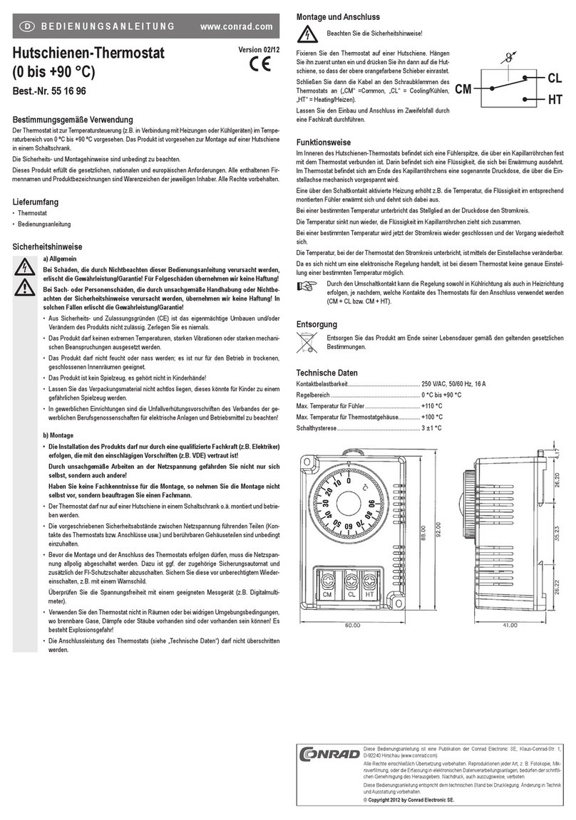
Conrad FHT80B-3 User manual

Version 07/13
Radio heating thermostat
„FHT80B-3“
Item no. 55 78 94
OPERATING INSTRUCTIONS

2
Introduction
Dear customer,
Thank you for purchasing this product.
This product meets the requirements of both current European and national guidelines.
In order to preserve this condition and ensure the safe operation of the product we kindly ask
you to carefully follow these operating instructions!
Please read the operating instructions completely and observe the safety and operation notes
before using the product!
All company names and product names contained herein are trademarks of the
respective owners. All rights reserved.
Should you have any further questions, please contact our technical advisory service:
Germany: Tel. no.: +49 9604 / 40 88 80
Fax. no.: +49 9604 / 40 88 48
e-mail: [email protected]
Mon. to Thur. 8.00am to 4.30pm
Fri. 8.00am to 2.00pm

3
Table of contents
Page
1. Prescribed use ............................................................................................................... 5
2. Scope of delivery ........................................................................................................... 5
3. Explanation of icons ..................................................................................................... 6
4. General information ...................................................................................................... 7
a) Functionality .............................................................................................................. 7
b) Security code ............................................................................................................ 8
c) Information on the range .......................................................................................... 9
5. Safety instructions ...................................................................................................... 10
a) General information ................................................................................................ 10
b) Batteries and rechargeable batteries .................................................................... 10
6. Inserting/replacing batteries ..................................................................................... 11
7. Control panel ................................................................................................................ 12
8. Mounting the ‘FHT80B-3’ to a wall ............................................................................ 13
a) Choosing a suitable installation location ............................................................... 13
b) Mounting the wall holder ........................................................................................ 13
9. Set date and time ......................................................................................................... 15
10. Mounting the ‘FHT8V’ valve operating mechanism ............................................... 18
a) Removing the old thermostats ............................................................................... 18
b) Inserting the batteries into the valve operating mechanism ................................. 18
c) Mounting the valve operating mechanism to the radiator .................................... 19
11. Mounting the door/window contact sensor ‘FHT80TF-2’ ...................................... 21
a) General information ................................................................................................ 21
b) Installation notes ..................................................................................................... 22
c) Installing the ‘FHT80TF-2’ ..................................................................................... 24
d) Initial operation of the ‘FHT80TF-2’ ....................................................................... 25
e) Setting the operating mode of the ‘FHT80TF-2’ ................................................... 26
12. Programming the system ........................................................................................... 27
a) Setting the comfort temperature, lowering temperature and the
‘Window open’ temperature ................................................................................... 27
b) Setting/changing the week profile .......................................................................... 29
c) Operating modes .................................................................................................... 32

4
Page
d) Button lock (for buttons and scroller) ..................................................................... 33
e) Switching between comfort temperature and lowering temperature ................... 34
f) Heating pause ......................................................................................................... 34
g) Closing the valve .................................................................................................... 35
h) Emergency operation of the valve operating mechanism .................................... 35
i) ‘Window open’ detection ........................................................................................ 36
13. Special functions ......................................................................................................... 37
a) Setting the decalcification time (‘CALC’) ............................................................... 38
b) Selecting the temperature unit (°C or °F) ............................................................. 39
c) Setting the date and time (‘dAt’) ............................................................................ 39
d) Setting the security code (‘CodE’) ......................................................................... 39
e) Setting the number of valve operating mechanisms (‘An A’) ............................... 42
f) Synchronising the valve operating mechanisms (‘SYnC’) ................................... 43
g) Test mode (‘tESt’) ................................................................................................... 44
h) Displaying the valve position (‘StEL’) .................................................................... 44
i) Connecting to the home radio central unit (‘CEnt’) ............................................... 45
j) Querying the status of a door/window contact sensor (‘FEn’) ............................. 46
k) Registering a door/window contact sensor ........................................................... 47
l) Deleting door/window contact sensors .................................................................. 48
m) Radiator offset (‘OFFS’) ......................................................................................... 49
14. Replacing the batteries............................................................................................... 50
a) ‘FHT80B-3’ heating control ....................................................................................50
b) ‘FHT8V’ valve operating mechanism..................................................................... 50
c) ‘FHT80TF-2’ door/window contact sensor ............................................................ 51
15. Troubleshooting .......................................................................................................... 52
16. Handling ........................................................................................................................ 53
17. Maintenance and cleaning ......................................................................................... 53
18. Disposal ........................................................................................................................ 54
a) General information ................................................................................................ 54
b) Battery/rechargeable battery disposal ................................................................... 54
19. Technical specifications ............................................................................................ 55
20. Declaration of conformity (DOC) ............................................................................... 55
5
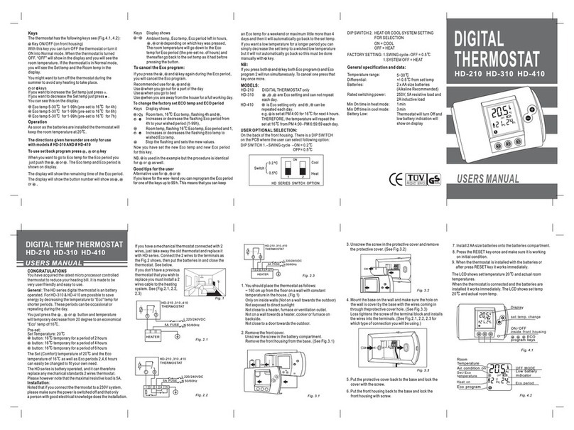
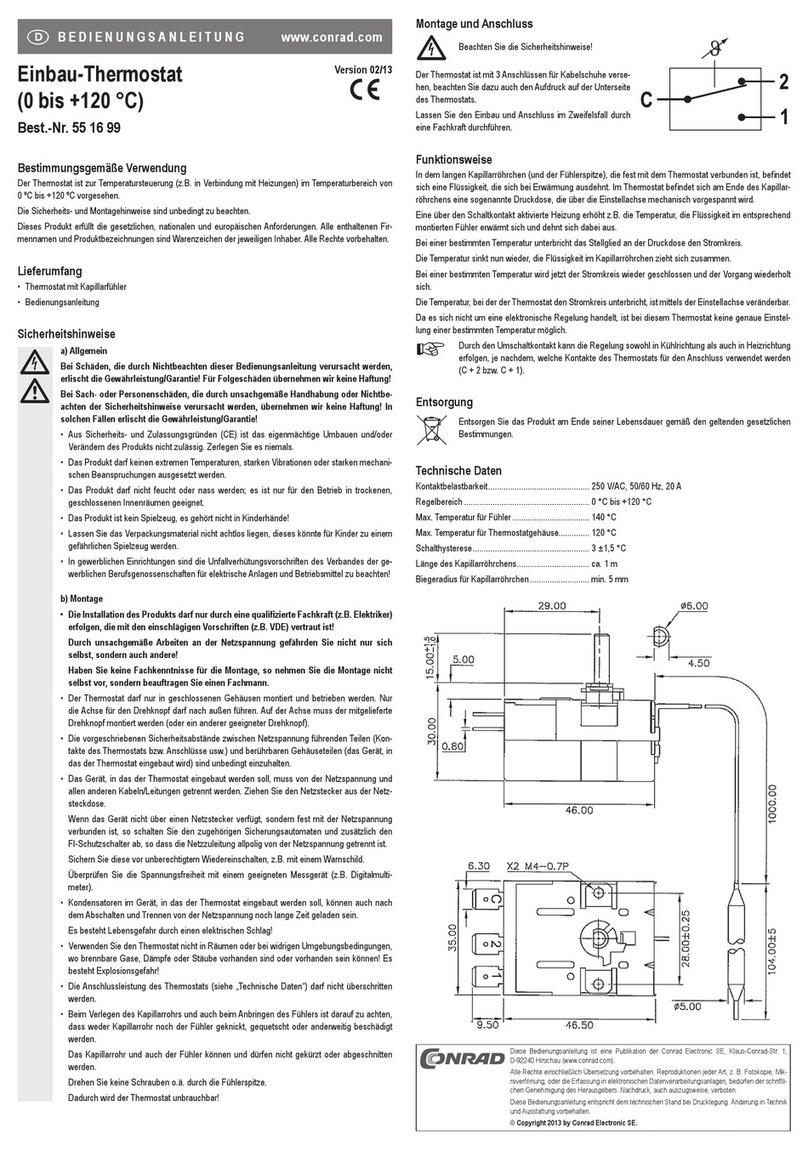
1. Prescribed use
The complete radio-controlled radiator thermostat system comprises three components:
• ‘FHT80B-3’ heating control/thermostat
• ‘FHT8V’ valve operating mechanism
• ‘FHT80TF-2’ door/window contact sensor
The system is used for temperature control in individual rooms in which the heat that dissipates
from radiators is controlled by reducing the flow of hot water in the heating system.
The ‘FHT80B-3’ heating control measures the room temperature by means of an integrated
sensor and transmits the corresponding control data to the ‘FHT8V’ valve operating mecha-
nisms.
The ‘FHT80B-3’ can analyse the status signals (window open/closed) of up to four ‘FHT80TF-
2’ door/window contact sensors and, in order to save energy when a room is aired, for example,
automatically reduce the temperature down to a so-called ‘Window open’ temperature, when
the room’s window is opened.
The ‘FHT80B-3’ also facilitates a bi-directional radio connection with the ‘FHZ1000’ home
radio central unit.
Any other use of the heating control (for example, in cooling systems, floor heating
systems, and so on) is not permitted and may lead to serious damage.
2. Scope of delivery
• ‘FHT80B-3’ heating control
• Wall mounting set (screws and dowels)
• User manual

6
3. Explanation of icons
The icon with a lightning flash in a triangle is used to alert you to potential personal
injury hazards such as electric shock.
An exclamation mark in a triangle indicates important information in these operating
instructions which must be observed without fail.
The ‘hand’ symbol provides special information and advice on operating the device.

7
4. General information
The radio-controlled radiator thermostat system has a number of advantages compared with
simple mechanical thermostats:
• The system is separated into radiator-mounted valve operating mechanisms and freely
positionable operation and control units (the ‘FHT80B-3’ heating control supplied here, for
example), which makes it easy to carry out all the necessary settings.
• The time program option makes it possible to adapt the system to the lifestyle of its users,
so that the room is always comfortably warm when it is used.
At other times energy can be saved by reducing the temperature. The inconvenient, manual
turning up and turning down of thermostats is no longer necessary.
• A calcification protection function is integrated into the system. Once a week (the time can
be set) the valve operating mechanism opens and closes the valve to prevent lime deposits
from blocking the valve.
• If a room’s windows are monitored by one or several ‘FHT80TF-2’ door/window contact
sensors, then the control unit automatically reduces the target temperature while the room
is aired.
Once the windows have been closed, the controller automatically restores the original
temperature.
• The ‘FHT80B-3’ heating control also facilitates the bi-directional communication with the
‘FHZ1000’ home radio central unit, which can perform universal control tasks.
This means that changes to the temperature settings or the time program can also
be carried out via the ‘FHZ1000’.
a) Functionality
The room temperature is measured and compared to the target temperature in the ‘FHT80B-
3’ heating control (set via the time program or manually).
The difference is used to calculate how far the valve has to be opened or closed to obtain the
desired temperature. Within a time period of approx. 2 minutes commands are then radio-
transmitted to the ‘FHT8V’ valve operating mechanism that is mounted to the radiator. The
valve operating mechanism then reduces or increases the heat accordingly.
The heating control’s integrated receiver also allows the ‘FHT80B-3’ to receive the status
signals from up to 4 ‘FHT80TF-2’ door/window contact sensors.

8
Changes (‘Window open’ or ‘Window closed’) are signalled to the heating control within a time
period of about 1 minute. This allows the heating control to adjust the temperature after an
average of 30 seconds, in order to save energy when a room is aired, for example.
b) Security code
The radio signal is protected by a two-part security code This security code protects the system
against interference from other radio systems and ensures that several radio-controlled
radiator thermostat systems can be operated separately in a household.
Each part of the code comprises 100 setting options. This means that a total of 10,000 different
security codes are available.
To ensure communication between the heating control and the valve operating mecha-
nism/s the same security code has to be set for all devices in a room.
A random security code is set by the manufacturer.
When supplied as a set (heating control and valve operating mechanism) the valve
operating mechanism is preset to the heating control’s security code.
If you purchased the heating control and valve operating mechanism separately (or
you want to use additional valve operating mechanisms for a heating control), then
the security code has to be transmitted to each of the valve operating mechanisms.
See section 13 d) or section 13 e).
The security code is also used for communicating with the ‘FHZ1000’ central unit.
The ‘FHT80TF-2’ door/window contact sensors are equipped with a randomly generated
factory default code that cannot be changed. Since over 16 million different codes are possible
for the ‘FHT80TF-2’, changing the code is not necessary.
Duplication is virtually impossible.

9
c) Information on the range
• The transmission power is less than 10 mW, much below that of a mobile phone which may
have a transmission power 200 times as great. Adverse effects on sensitive people and
animals are not to be expected.
• The wireless radiator thermostat system uses the 868 MHz range, which is also used by
other radio services. Therefore devices that operate on the same or neighbouring frequen-
cies may restrict both its operation and its range.
• The specified range of up to 100 m (to the ‘FHT8V’ valve operating mechanism) or up to
300 m (to the ‘FHZ1000’) is the free-field range, which means the range with visual contact
between the transmitter and receiver. In practice, however, walls, ceilings, etc. between the
transmitter and the receiver may affect and reduce the range.
Other causes of reduced ranges:
• All types of high-frequency interference
• Any buildings or vegetation
• Conductive metal parts that are located near the devices or within or near their transmission
path, for example, radiators, metallised insulation glass windows, reinforced concrete
ceilings, etc.
• Influence on the radiation pattern of antennas due to the distance from the transmitter or
receiver to conductive surfaces or objects (also to human bodies or the ground)
• Broadband interference in urban areas that reduces the signal-to-noise ratio; the signal is
no longer recognised due to this ‘noise’
• Interference radiation resulting from insufficiently shielded electronic devices, for example,
operating computers or similar

10
5. Safety instructions
The product’s guarantee becomes invalid if the product is damaged as a
result of failure to observe these operating instructions. We do not assume
any liability for any resulting damages!
Nor do we assume liability for damage to property or personal injury caused
by improper use or failure to observe the safety instructions. In such cases
the product’s guarantee becomes invalid!
a) General information
Do not use this product in hospitals or medical institutions. Although the product emits only
relatively weak radio signals, these may cause life-support systems to malfunction. This may
also be the case in other areas.
The product is only suitable for use in dry indoor rooms.
The product is not a toy and should be kept out of the reach of children.
For safety and licensing (CE) reasons any unauthorised alterations to and/or modification of
the product are not permitted.
Do not leave packaging material lying around. This may become a dangerous plaything in the
hands of children.
Handle the product with care; knocks, blows or even a fall from a low height can damage it.
b) Batteries and rechargeable batteries
• Keep batteries/rechargeable batteries out of the reach of children.
• Make sure that the polarity is correct when inserting the batteries/rechargeable batteries.
• Do not leave batteries/rechargeable batteries lying around as they could be swallowed by
children or pets. In such case seek immediate medical care.
• Leaking or damaged batteries/rechargeable batteries may cause acid burns, if they come
into contact with skin. Therefore, please make sure you use suitable protective gloves.
• Make sure that batteries/rechargeable batteries are not short-circuited or thrown into a fire.
They might explode!
• Never disassemble batteries/rechargeable batteries!

11
• Conventional batteries must not be recharged. They might explode!
• If the device is not used for a longer period of time (when stored, for example), remove the
inserted batteries/rechargeable batteries to prevent them from leaking and causing dam-
age.
6. Inserting/replacing batteries
• Slide down and remove the wall holder on the back of the heating control.
• To open the battery compartment slide down and remove its cover (see the arrow imprinted
on the cover).
• Insert two high-quality alkaline Mignon/AA batteries; ensure correct polarity. You will find
corresponding figures in the battery compartment.
Make sure that you insert the batteries correctly to avoid damaging the heating
control’s electronic components.
• Close the battery compartment again.
Although you can use rechargeable batteries to operate the heating control, both
the battery life and the range will be reduced. If you experience any problems whilst
operating the heating control with rechargeable batteries, use conventional alkaline
batteries, as described above.
• The heating control performs a short display test, after which you can set the date and the
time. See section 9, page 15.
• If the battery icon (‘ ’) appears, the batteries are used up and should be changed as soon
as possible. The same applies if the radio range decreases or if data are no longer displayed
on the LC display.

12
7. Control panel
Figure 1
AScroller for settings
B‘FUNKTION’ button
C‘PROG’ button
D‘’ button
ELC display
A
D
C
E
B
F
U
N
K
T
I
O
N
P
R
O
G

13
8. Mounting the ‘FHT80B-3’ to a wall
a) Choosing a suitable installation location
Choose a suitable location for mounting the ‘FHT80B-3’ heating control. This has to meet the
following requirements:
• Central position in the room in which the temperature is to be controlled
• Easy access for convenient operation
• Installation at eye level for easy reading of the display
• Not a poorly insulated outer wall
• No direct sunlight
• No interference from heat sources such as radiators, TVs, lamps, refrigerators, etc.
• No mounting next to a window
• The greatest possible distance to metal objects to avoid any unnecessary reduction of the
operating range
b) Mounting the wall holder
Proceed as follows to mount the wall holder:
• Remove the wall holder from the back of the heating control,
by sliding it down and out.
• Place the wall holder vertically against the wall with the round
side pointing up, see figure 2.
• Mark the positions of the bore holes through the two slotted
holes.
• Depending on the type of wall, drill 6mm holes and insert
suitable dowels before mounting the holder.
Figure 2
When drilling, be careful not to damage any power supply lines, gas or water pipes!
Life-threatening danger!

14
• Fix the wall holder into place using, for example, the enclosed screws. Make sure that the
two recessed slotted holes for the screws point in your direction.
• Before attaching the heating control to the wall holder insert the batteries, if you have not
done so already. See section 6, page 11.
• You can now slide the heating control into the wall holder from above.

15
9. Set date and time
• If there is a protective film over the display, remove it first.
• If no batteries have been inserted yet, follow the instructions in section 6, page 11 to insert
them.
After inserting the batteries, an automatic display test is performed (all segments and
readouts of the LCD briefly appear).
After the display test you can set the year, month, day, hour and minute on the heating
control.
Use the scroller to change the displayed values. To confirm your selection, briefly
press the ‘PROG’ button.
• After inserting the batteries, the year is displayed:
0612 18 24
MO DI MI DO FR SA SO
Figure 3
Use the scroller to set the year. To confirm your setting, briefly press the ‘PROG’ button.
• The month is displayed:
0612 18 24
MO DI MI DO FR SA SO
Figure 4
Use the scroller to set the month and confirm your setting by pressing the ‘PROG’ button.

16
• The day is displayed:
0612 18 24
MO DI MI DO FR SA SO
Figure 5
Use the scroller to set the day and confirm your setting by pressing the ‘PROG’ button.
• The hours are displayed:
0612 18 24
MO DI MI DO FR SA SO
Figure 6
Use the scroller to set the hour of the day and confirm your setting by pressing the ‘PROG’
button.
• The minutes are displayed:
0612 18 24
MO DI MI DO FR SA SO
Figure 7
Use the scroller to set the minutes of the hour and confirm your setting by pressing the
‘PROG’ button.

17
• The LCD then displays the current security code and ‘120’.
• The heating control counts down from ‘120’ in steps of 1 second and then returns to the
normal operating mode.
During this time the heating control cannot be operated. The heating control
now synchronises its operation with the valve operating mechanisms.
Please make a note of the displayed security code on a slip of
paper and write the name of the room, in which the heating
control is installed, underneath the code.
You will need this information, if you intend to register the
heating control to a ‘FHZ1000’ home radio central unit.
• Slide the heating control onto the wall holder from above until it
snaps into place. See figure 8 on the right.
Figure 8

18
10.Mountingthe‘FHT8V’valveoperatingmechanism
To save you from having to laboriously read through several user manuals (heating control and
valve operating mechanism) we have included information on how to mount and start up the
‘FHT8V’ valve operating mechanism on the following pages.
The valve operating mechanism is not supplied with the heating control and must
be ordered separately.
a) Removing the old thermostats
• Remove the old mechanical thermostats.
• If any of the screw connections have seized up you can use
multigrip pliers. Release the thermostats by turning anticlock-
wise.
b) Inserting the batteries into the valve operating mechanism
• Remove the battery compartment cover of the valve
operating mechanism by sliding it down and out.
• Insert two AA batteries into the battery compartment.
Make sure that you observe the correct polarity when
you insert the batteries. See the figures in the battery
compartment and in the image on the right.
•‘
C1C1
C1C1
C1’ is displayed, followed by a two-digit number. ‘C2C2
C2C2
C2’
isthendisplayed,followedbyanothertwo-digitnumber.
These two numbers are the currently stored 2-part
security code of the valve operating mechanism (11
and 22 = security code 1122, for example).
• A signal tone is then generated and ‘A1A1
A1A1
A1’ is displayed.
• The valve operating mechanism fully retracts the
control pin to facilitate mounting.
• After this ‘A2A2
A2A2
A2’ is displayed.
Figure 9
Figure 10

19
c) Mounting the valve operating mechanism to the radiator
• Manually turn the coupling nut to fasten the valve operat-
ing mechanism to the valve (‘1’ in the figure on the right).
When using ‘Danfoss’ valves mount one of the enclosed
adapters to the valve first. The figures 12a, 12b, and 12c
on the next page show the adapters that have to be used
for each valve. Additional adapters for other valves may
be purchased separately.
• Briefly press the button (2) on the valve operating mecha-
nism once. See the figure on the right.
•‘
A3A3
A3A3
A3’ appears on the valve operating mechanism’s LCD
and the valve is closed.
• The antenna symbol then blinks on the display and
‘0%0%
0%0%
0%’ is displayed.
• Close the battery compartment again.
Please note:
If you purchased the valve operating mechanism separately and not as part of a set
comprising a heating control and valve operating mechanism, for example, then the
security code must first be transmitted. This is described in detail in section 13 d).
• The valve operating mechanism acknowledges receipt of the first wireless protocol with a
signal tone.
• The antenna symbol s now permanently displayed.
• This completes the installation and you can now adapt the pre-programmed settings to your
individual needs.
Please note:
Proceedasdescribedabove,ifyouwishtoinstallfurthervalveoperatingmechanisms.
Afterwards, the number of radiators/valve operating mechanisms must be set on
the heating control (section 13 e) and the security code must be transmitted (section
13 d).
Figure 11

20
Examples of ‘Danfoss’ adapters:
Figure 12a, type ‘RA’
Figure 12b, type ‘RAV’
Figure 12c, type ‘RAVL’
After attaching the adapters for valves of the type ‘RAV’ and ‘RA’ to the valve body, the
adapters should be fastened using the enclosed screw and nut.
For valves of the type ‘RAV’ you should also place the cylindrical extension piece onto the valve
pin.
Table of contents
Other Conrad Thermostat manuals

Conrad
Conrad 55 16 96 User manual

Conrad
Conrad 55 16 99 User manual

Conrad
Conrad UT 200 User manual

Conrad
Conrad UT 100 User manual

Conrad
Conrad 61 88 88 User manual

Conrad
Conrad HD-210 User manual

Conrad
Conrad 56 18 00 Programming manual

Conrad
Conrad 61 05 78 User manual

Conrad
Conrad 56 00 76 User manual

Conrad
Conrad FHT8R User manual