Energate AW000873 User manual

AW000873
Installation Guide for Energate
Thermostats
Rev Date Done By Che ked
By
Des ription
A Dec 22,
2011
G. Delage S.
McKenzie
Initial Release
B Jan 25,
2012
G. Delage S.
McKenzie
Added infor ation on AS20
Auxiliary Switch, dual
transfor er scenarios. Added
FAQ and Troubleshooting
sections.

THIS DOCUMENT CONTAINS CONFIDENTIAL INFORMATION PROPRIETARY TO ENERGATE INC. NO PART OF ITS CONTENTS MAY BE
DISCLOSED OR CONVEYED TO, USED BY, OR COPIED TO A THIRD PARTY WITHOUT PRIOR WRITTEN CONSENT BY ENERGATE INC.
2
Table of Contents
1. Introd ction ................................................................................................................................. 3
1.1 Operating the Thermostat ...................................................................................................... 3
2. Installation Proced re ................................................................................................................. 5
3. No Existing Thermostat .............................................................................................................. 6
4. Thermostat Wiring ...................................................................................................................... 7
5. Config ring the Thermostat Settings .......................................................................................... 8
6. Standard Config rations ........................................................................................................... 10
6.1 F rnace with Air Conditioner ............................................................................................. 10
6.2 F rnace with No Air Conditioner........................................................................................ 11
6.3 Air Conditioner with no f rnace ......................................................................................... 12
6.4 Heat P mp - Single stage with no a xiliary stage ............................................................... 13
6.5 Heat P mp - Two stage with no a xiliary stage.................................................................. 14
6.6 Heat P mp - Single stage with a xiliary stage .................................................................... 15
6.7 Heat P mp - Two stage with a xiliary stage....................................................................... 16
7. Special Config rations .............................................................................................................. 17
7.1 No Common Wire at thermostat ......................................................................................... 17
7.2 D al transformer scenarios.................................................................................................. 22
7.3 Zone Control Systems ......................................................................................................... 24
8. Options and Accessories ........................................................................................................... 25
8.1 Energate thermostat does not cover hole in wall (Wall Plate) ............................................ 25
8.2 O tdoor Sensor .................................................................................................................... 26
8.3 Air Filter Sensor .................................................................................................................. 26
8.4 Heat P mp Fa lt Sensor ...................................................................................................... 26
9. Testing the System .................................................................................................................... 27
9.1 Conventional System Test ................................................................................................... 27
9.2 Heat-P mp System Test ...................................................................................................... 28
10. Tro bleshooting ...................................................................................................................... 29
10.1 S spected installation iss e ............................................................................................... 29
10.2 Ret rn to Material A thorization (RMA) Proced re ........................................................ 31
11. Commissioning a thermostat................................................................................................... 32
12. Uns pported Config rations ................................................................................................... 33
13. Freq ently Asked Q estions ................................................................................................... 34
14. Energate Technical S pport .................................................................................................... 37

THIS DOCUMENT CONTAINS CONFIDENTIAL INFORMATION PROPRIETARY TO ENERGATE INC. NO PART OF ITS CONTENTS MAY BE
DISCLOSED OR CONVEYED TO, USED BY, OR COPIED TO A THIRD PARTY WITHOUT PRIOR WRITTEN CONSENT BY ENERGATE INC.
3
1. Introduction
This doc ment is intended for the se of installers who are installing Energate Z100 thermostat
(both Pioneer 1 and Pioneer 2 models).
The Energate Z100 is a 2-way comm nicating thermostat that s pports the ZigBee Smart Energy
protocol. This doc ment describes the typical installation scenarios and provides advice for
handling n s al sit ations. Section 1.1 describes how to operate the thermostat.
If yo have q estions that are not answered by this doc ment, please contact Energate s pport as
shown in section 13.
1.1 Operating the Thermostat
Navigating the Controls
The f nction of the LEFT and RIGHT TAB b ttons appears on the bottom of the display screen.
Use the SCROLL (▲ ▼) b ttons to adj st the temperat re, move thro gh the men s options, and
change highlighted val es. Press the MENU / SELECT (√) b tton to access the men as well as
to select or accept highlighted men items.

THIS DOCUMENT CONTAINS CONFIDENTIAL INFORMATION PROPRIETARY TO ENERGATE INC. NO PART OF ITS CONTENTS MAY BE
DISCLOSED OR CONVEYED TO, USED BY, OR COPIED TO A THIRD PARTY WITHOUT PRIOR WRITTEN CONSENT BY ENERGATE INC.
4
Home Screen
The Home screen displays c rrent temperat re and operation data. When the Home screen is in
Idle mode, the backlight is on with low brightness. Please note that icons s ch as heat or fan are
animated when the eq ipment is r nning.
Note: A SETPOINT (e.g., LEAVE) is identified by a name and specifies both heating and
cooling target temperat res. See the Temperat re SettingsError! No bookmark name given.
section for additional information.
By j st pressing any of the b ttons, the Home screen becomes Active, the backlight brightens
and the MODE and FAN tabs are shown.
Pressing the LEFT TAB b tton changes the thermostat mode
(COOL/HEAT/AUTO/EMERG/OFF). The available options for the thermostat mode will
depend on the type of heating or cooling eq ipment at yo r home. Pressing the RIGHT TAB
b tton changes the fan mode (ON/AUTO)
Pressing the SCROLL (▲ ▼) b ttons makes the temperat res of the SETPOINTs higher
(warmer) or lower (cooler). Yo can accept the changes by pressing the LEFT TAB, which will
be displaying ACCEPT, or yo can walk away after making the changes. They will be
a tomatically accepted when the screen goes to the Idle mode (i.e. the backlight diminishes to
low).
To see the different men items displayed, the MENU / SELECT (√) b tton needs to be pressed
once when the screen is active or twice when it is in the Idle mode.
Note: Refer to the thermostat man al for complete operating instr ctions.

THIS DOCUMENT CONTAINS CONFIDENTIAL INFORMATION PROPRIETARY TO ENERGATE INC. NO PART OF ITS CONTENTS MAY BE
DISCLOSED OR CONVEYED TO, USED BY, OR COPIED TO A THIRD PARTY WITHOUT PRIOR WRITTEN CONSENT BY ENERGATE INC.
5
2. Installation Procedure
1. If there is no existing thermostat, please review section 3, "No Existing Thermostat" for
g idelines on mo nting the thermostat and related eq ipment.
2. Before installing the new thermostat in the home, verify that the existing HVAC
eq ipment is working correctly by testing all heating and cooling stages.
3. Before disconnecting the old thermostat, record the sched le and eq ipment settings and
label all the wires identifying the terminals they are connected to on the old thermostat in
case it needs to be re-installed.
4. Disconnect power from the HVAC eq ipment, remove the old thermostat and install the
Energate Z100 thermostat as per section 6. In the event that there is no gro nd wire,
please review section 7.1. In the event that the thermostat backplate does not cover an
existing hole in the wall, please review section 8.1.
5. After installing the Energate Z100 thermostat, reconnect power and enter the Set p men
to config re the thermostat for the type of eq ipment it is connected to as shown in
section 5.
6. Verify that all the heating and cooling stages are working correctly as shown in section 9.
7. If sing an o tdoor sensor, air filter sensor or heat p mp fa lt sensor, please review
section 8.
8. If the HVAC eq ipment ses two transformers, please review section 7.2.
9. If the HVAC eq ipment is wired into a zone control system, please review section 7.3.
10. Commission the thermostat to join it to the gateway, verify the thermostat radio indicator
in the top left of the display changes from an “X” to a series of signal strength bars as
shown in section 10.
11. Show the homeowner how to se their new thermostat as per section 1.1. In partic lar
make s re they know how to:
a. Change the mode between Heat, Cool, A to and Off
b. Set a temporary hold, which can also be sed to override an event
c. Modify their conservation settings if the Utility is sending price information
d. Modify their sched le time and temperat re settings
12. Explain how the tility program works to the homeowner.
13. Provide the homeowner with the thermostat man al and Utility doc mentation.

THIS DOCUMENT CONTAINS CONFIDENTIAL INFORMATION PROPRIETARY TO ENERGATE INC. NO PART OF ITS CONTENTS MAY BE
DISCLOSED OR CONVEYED TO, USED BY, OR COPIED TO A THIRD PARTY WITHOUT PRIOR WRITTEN CONSENT BY ENERGATE INC.
6
. No Existing Thermostat
Mounting the Thermostat
Install the thermostat at 5 feet (1.5m) above the floor in an area with good air circ lation at
average temperat re. Avoid locations with drafts or dead spots behind doors, hot or cold air
d cts, s nlight or radiant heat from appliances, concealed pipes or chimneys and nconditioned
areas s ch as o tside walls behind the thermostat.
The 2 wallplate anchors sho ld be spaced 3.5 inches (90 mm) apart in a vertical direction. P ll
wires thro gh the backplate and connect to the appropriate terminals as defined in the Wiring
Config ration.
Mounting the Outdoor Sensor
The o tdoor sensor sho ld be mo nted in a shaded location, o t of direct s nlight. The
thermostat will a tomatically detect the o tdoor sensor and display its readings.
Cleaning the Thermostat
The thermostat can be cleaned with a soft cloth lightly dampened with isopropyl alcohol (IPA).
Excessive IPA or use of o her solven s may damage he LCD!
Removing Thermostat Front Housing from Backplate
To remove the thermostat front ho sing from the backplate, press the plastic tab located at the
bottom of the thermostat. P ll the bottom of the front ho sing forward and remove.
Warning: do not use metallic tools when removing battery or backplate; this may damage the
thermostat.

THIS DOCUMENT CONTAINS CONFIDENTIAL INFORMATION PROPRIETARY TO ENERGATE INC. NO PART OF ITS CONTENTS MAY BE
DISCLOSED OR CONVEYED TO, USED BY, OR COPIED TO A THIRD PARTY WITHOUT PRIOR WRITTEN CONSENT BY ENERGATE INC.
7
4. Thermostat Wiring
The following diagram shows the backplate of the Energate thermostat.
Conventional System
The following are the general wiring connections for a conventional system.
Conventional Systems (CONV)
1
Co on(GND)
C
8
2
Power (24VAC)
R
9
3
RS OUT
Outdoor Sensor
1st Stage Heat
W1
10
4
RS GND
Sensor Ground
Fan
G
11
5
FILTER
Filter
1st Stage Cool
Y1
12
6
2nd Stage Cool
Y2
13
7
2nd Stage Heat
W2
14
Heat Pump
The following are the general wiring connections for a heat p mp.
Heat Pump Systems (HP)
1
Co on (GND)
C
8
2
FAULT
Heat Pu p Fault
Power (24VAC)
R
9
3
RS OUT
Outdoor Sensor
Auxiliary Heat
E
10
4
RS GND
Sensor Ground
Fan
G
11
5
FILTER
Filter
1st Stage Heat Pu p
Y1
12
6
2nd Stage Heat Pu p
Y2
13
7
Reversing Valve*
O/B
14
* Reversing Valve is also known as Changeover valve

THIS DOCUMENT CONTAINS CONFIDENTIAL INFORMATION PROPRIETARY TO ENERGATE INC. NO PART OF ITS CONTENTS MAY BE
DISCLOSED OR CONVEYED TO, USED BY, OR COPIED TO A THIRD PARTY WITHOUT PRIOR WRITTEN CONSENT BY ENERGATE INC.
8
5. Configuring the Thermostat Settings
In order to config re the Thermostat to match yo r HVAC config ration, yo m st se the
SETUP men .
1. Press the Men /Select (checkmark) b tton to enter the men
2. Scroll down to the SETUP men
3. Enter the Install Password “INST”
This will give yo access to the additional men items listed below.
Equipment Type
• TYPE:
o Select the type of eq ipment (conventional or heat p mp), the defa lt is
Conventional.
• # OF COOL STAGES:
o Select the n mber of cool stages from 0 to 2, the defa lt is 1.
• # OF HEAT STAGES:
o Select the n mber of heat stages from 0 to 2 (3 for heat p mps), the defa lt is 1.
• REV. VALVE (for heat p mps only):
o Select whether the reversing valve is on in cool or on in heat. The defa lt is on in
cool.
Equipment Settings
• MIN ON/OFF TIME:
o Select the minim m on/off time from 1 to 6 min tes, the defa lt is 3.
o A minim m of 2 min tes is recommended for a f rnace and 3 min tes for Heat
P mps and Air Conditioners.
• FAN ON IN HEAT (for conventional eq ipment only):
o Set to yes if the thermostat controls the fan (common in electric f rnaces) and no
if the f rnace controls the fan (common in gas f rnaces). The defa lt is Yes.
• ALLOW HP+AUX ON (for heat p mps only):
o Set to yes if the heat p mp and a xiliary heat can be on at the same time fan
(common with a xiliary electric heat).
o Set to no if the heat p mp sho ld be off when the a xiliary heat is on (common
with a xiliary fossil f el heat).
o The defa lt is Yes.
• BALANCE POINTS (Only for heat p mps with o tdoor temperat re sensor):
o HIGH: Set to the temperat re above which the a xiliary heat is disabled. The
range is from -38 °F (-39 °C) to 122 °F (50 °C) and the defa lt is 122 °F (50 °C)
and a typical val e is 50 °F (10 °C).
o LOW: Set to the temperat re below which the heat p mp is disabled. The range
is from -40 °F (-40 °C) to 120 °F (49 °C) and the defa lt is -40 °F (-40 °C) and a
typical val e is 32 °F (0 °C).

THIS DOCUMENT CONTAINS CONFIDENTIAL INFORMATION PROPRIETARY TO ENERGATE INC. NO PART OF ITS CONTENTS MAY BE
DISCLOSED OR CONVEYED TO, USED BY, OR COPIED TO A THIRD PARTY WITHOUT PRIOR WRITTEN CONSENT BY ENERGATE INC.
9
Control
• HYSTERISIS
o Select the n mber of degrees the temperat re m st go beyond a setpoint prior to
changing from HEAT to COOL mode or vice versa when in AUTO mode. The
range is 0 °F (0 °C) to 6 °F (3 °C) and the defa lt is 2 °F (1 °C).
• ANTICIPATION TIME
o Select the amo nt of time the thermostat will engage the eq ipment to reach the
setpoint temperat re before the sched led setpoint time. The range is from 0 to
180 min tes and the defa lt is 60 min tes.
• MAX RECOVERY TIME (for m ltiple stage eq ipment):
o Select the amo nt of time the thermostat will allow the eq ipment to reach the
desired temperat re in the c rrent stage before engaging the next stage of heating
or cooling. The range is 0 to 180 min tes and the defa lt is 90 min tes.

THIS DOCUMENT CONTAINS CONFIDENTIAL INFORMATION PROPRIETARY TO ENERGATE INC. NO PART OF ITS CONTENTS MAY BE
DISCLOSED OR CONVEYED TO, USED BY, OR COPIED TO A THIRD PARTY WITHOUT PRIOR WRITTEN CONSENT BY ENERGATE INC.
10
6. Standard Configurations
6.1 Furnace with Air Conditioner
Equipment Wiring
Thermostat Settings
Equipment Type
• TYPE: Conventional
• # OF COOL STAGES: 1 for single stage air conditioner, 2 for two stage air conditioner
• # OF HEAT STAGES: 1 for single stage f rnace, 2 for two stage f rnace.
Equipment Settings
• FAN ON IN HEAT: Set to yes if the thermostat controls the fan (common in electric
f rnaces) and no if the f rnace controls the fan (common in gas f rnaces).

THIS DOCUMENT CONTAINS CONFIDENTIAL INFORMATION PROPRIETARY TO ENERGATE INC. NO PART OF ITS CONTENTS MAY BE
DISCLOSED OR CONVEYED TO, USED BY, OR COPIED TO A THIRD PARTY WITHOUT PRIOR WRITTEN CONSENT BY ENERGATE INC.
11
6.2 Furnace with No Air Conditioner
Equipment Wiring
Thermostat Settings
Equipment Type
• TYPE: Conventional
• # OF COOL STAGES: 0
• # OF HEAT STAGES: 1 for single stage f rnace, 2 for two stage f rnace.
Equipment Settings
• FAN ON IN HEAT: Set to yes if the thermostat controls the fan (common in electric
f rnaces) and no if the f rnace controls the fan (common in gas f rnaces).

THIS DOCUMENT CONTAINS CONFIDENTIAL INFORMATION PROPRIETARY TO ENERGATE INC. NO PART OF ITS CONTENTS MAY BE
DISCLOSED OR CONVEYED TO, USED BY, OR COPIED TO A THIRD PARTY WITHOUT PRIOR WRITTEN CONSENT BY ENERGATE INC.
12
6. Air Conditioner with no furnace
Equipment Wiring
Thermostat Settings
Equipment Type
• TYPE: Conventional
• # OF COOL STAGES: 1 for single stage air conditioner, 2 for two stage air conditioner
• # OF HEAT STAGES: 0

THIS DOCUMENT CONTAINS CONFIDENTIAL INFORMATION PROPRIETARY TO ENERGATE INC. NO PART OF ITS CONTENTS MAY BE
DISCLOSED OR CONVEYED TO, USED BY, OR COPIED TO A THIRD PARTY WITHOUT PRIOR WRITTEN CONSENT BY ENERGATE INC.
13
6.4 Heat Pump - Single stage with no auxiliary stage
Equipment Wiring
Thermostat Settings
Equipment Type
• TYPE: Heat P mp
• # OF COOL STAGES: 1
• # OF HEAT STAGES: 1
• REV. VALVE:
o Select whether the reversing valve is on in cool or on in heat. The defa lt is on in
cool.
Equipment Settings
• ALLOW HP+AUX ON:
o Set to yes if the heat p mp and a xiliary heat can be on at the same time fan
(common with a xiliary electric heat).
o Set to no if the heat p mp sho ld be off when the a xiliary heat is on (common
with a xiliary fossil f el heat).
o The defa lt is Yes.

THIS DOCUMENT CONTAINS CONFIDENTIAL INFORMATION PROPRIETARY TO ENERGATE INC. NO PART OF ITS CONTENTS MAY BE
DISCLOSED OR CONVEYED TO, USED BY, OR COPIED TO A THIRD PARTY WITHOUT PRIOR WRITTEN CONSENT BY ENERGATE INC.
14
6.5 Heat Pump - Two stage with no auxiliary stage
Equipment Wiring
Thermostat Settings
Equipment Type
• TYPE: Heat P mp
• # OF COOL STAGES: 2
• # OF HEAT STAGES: 2
• REV. VALVE:
o Select whether the reversing valve is on in cool or on in heat. The defa lt is on in
cool.
Equipment Settings
• ALLOW HP+AUX ON:
o Set to yes if the heat p mp and a xiliary heat can be on at the same time fan
(common with a xiliary electric heat).
o Set to no if the heat p mp sho ld be off when the a xiliary heat is on (common
with a xiliary fossil f el heat).
o The defa lt is Yes.

THIS DOCUMENT CONTAINS CONFIDENTIAL INFORMATION PROPRIETARY TO ENERGATE INC. NO PART OF ITS CONTENTS MAY BE
DISCLOSED OR CONVEYED TO, USED BY, OR COPIED TO A THIRD PARTY WITHOUT PRIOR WRITTEN CONSENT BY ENERGATE INC.
15
6.6 Heat Pump - Single stage with auxiliary stage
Equipment Wiring
Thermostat Settings
Equipment Type
• TYPE: Heat P mp
• # OF COOL STAGES: 1
• # OF HEAT STAGES: 2
• REV. VALVE:
o Select whether the reversing valve is on in cool or on in heat. The defa lt is on in
cool.
Equipment Settings
• ALLOW HP+AUX ON:
o Set to yes if the heat p mp and a xiliary heat can be on at the same time fan
(common with a xiliary electric heat).
o Set to no if the heat p mp sho ld be off when the a xiliary heat is on (common
with a xiliary fossil f el heat).
o The defa lt is Yes.
• BALANCE POINTS (Only for heat p mps with o tdoor temperat re sensor):
o HIGH: Set to the temperat re above which the a xiliary heat is disabled. The
range is from -38 °F (-39 °C) to 122 °F (50 °C) and the defa lt is 122 °F (50 °C)
and a typical val e is 50 °F (10 °C).
o LOW: Set to the temperat re below which the heat p mp is disabled. The range
is from -40 °F (-40 °C) to 120 °F (49 °C) and the defa lt is -40 °F (-40 °C) and a
typical val e is 32 °F (0 °C).

THIS DOCUMENT CONTAINS CONFIDENTIAL INFORMATION PROPRIETARY TO ENERGATE INC. NO PART OF ITS CONTENTS MAY BE
DISCLOSED OR CONVEYED TO, USED BY, OR COPIED TO A THIRD PARTY WITHOUT PRIOR WRITTEN CONSENT BY ENERGATE INC.
16
6.7 Heat Pump - Two stage with auxiliary stage
Equipment Wiring
Thermostat Settings
Equipment Type
• TYPE: Heat P mp
• # OF COOL STAGES: 1
• # OF HEAT STAGES: 2
• REV. VALVE:
o Select whether the reversing valve is on in cool or on in heat. The defa lt is on in
cool.
Equipment Settings
• ALLOW HP+AUX ON:
o Set to yes if the heat p mp and a xiliary heat can be on at the same time fan
(common with a xiliary electric heat).
o Set to no if the heat p mp sho ld be off when the a xiliary heat is on (common
with a xiliary fossil f el heat).
o The defa lt is Yes.
• BALANCE POINTS (Only for heat p mps with o tdoor temperat re sensor):
o HIGH: Set to the temperat re above which the a xiliary heat is disabled. The
range is from -38 °F (-39 °C) to 122 °F (50 °C) and the defa lt is 122 °F (50 °C)
and a typical val e is 50 °F (10 °C).
o LOW: Set to the temperat re below which the heat p mp is disabled. The range
is from -40 °F (-40 °C) to 120 °F (49 °C) and the defa lt is -40 °F (-40 °C) and a
typical val e is 32 °F (0 °C).

THIS DOCUMENT CONTAINS CONFIDENTIAL INFORMATION PROPRIETARY TO ENERGATE INC. NO PART OF ITS CONTENTS MAY BE
DISCLOSED OR CONVEYED TO, USED BY, OR COPIED TO A THIRD PARTY WITHOUT PRIOR WRITTEN CONSENT BY ENERGATE INC.
17
7. Special Configurations
7.1 No Common Wire at thermostat
In the event of a common wire not being available on the thermostat back plate it will be
necessary to either:
• install an Energate A xiliary Switch AS20 (No Common Wire and D al Transformer
scenarios)
• install an Energate A xiliary Switch AS10 (No Common Wire scenario)
• r n a gro nd wire from the eq ipment to the thermostat back plate (No Common Wire
scenario)
In most sit ations, it will be more efficient to install the AS20 a xiliary switch.
Several nits on the market were able to f nction witho t a common wire in 'power stealing
mode' or 'battery powered mode'. The battery incl ded with the Energate thermostat is s fficient
to maintain cr cial information d ring loss of mains power. However, the thermostat req ires
more power than can be obtained sing 'power stealing' or 'battery powered' mode which is why
it is req ired to be mains powered.

THIS DOCUMENT CONTAINS CONFIDENTIAL INFORMATION PROPRIETARY TO ENERGATE INC. NO PART OF ITS CONTENTS MAY BE
DISCLOSED OR CONVEYED TO, USED BY, OR COPIED TO A THIRD PARTY WITHOUT PRIOR WRITTEN CONSENT BY ENERGATE INC.
18
Installing the Auxiliary Switch (AS20)
AS20 Auxiliary Swit h Installation Guide
Missing Co on Wire on Single transfor er HVAC Syste
The Auxiliary Switch facilitates the installation of a
ther ostat where a co on wire connection fro the
heating and/or cooling equip ent to the ther ostat does not
exist.
These Single transfor er instructions on this page should be
used with a Heat only HVAC installation or an integrated
Heat/Cool installation using a single transfor er servicing
both Heat and Cool parts of the equip ent. For installations
with separate Heat and Cool equip ent, each with its own
transfor er, please refer to the instructions on Page 2.
The Auxiliary Switch is installed on or close to the equip ent
so that the five wire cable reaches the control ter inals
inside. The Auxiliary Switch should not be installed inside
the HVAC equip ent enclosure (doing so ay void the
HVAC UL certification).
Before Starting the Installation:
Check that the package includes 1 Auxiliary Switch Unit, 1
signal coupler and 5 Splice Wire Caps.
Turn off the power to the furna e, air onditioning
and/or heat pump, either at the shut off swit h, or at the
ele tri al panel.
Thermostat site:
Step 1 - Re ove the old ther ostat fro the backplate. If
there is no backplate then re ove the ther ostat fro the
wall to access the wiring. Next label the wires according to
which ter inal block they are currently connected
(R,Y,W,G). Now disconnect the wires and re ove the
existing backplate.
Step 2 – Mount the new backplate and connect the wire
arked R to the R ter inal block. Also connect the wires
labelled W and Y to the corresponding ter inal blocks.
Step 3 – Install the signal coupler provided with the Auxiliary
Switch between G and C ter inal blocks on the backplate.
Connect the wire labelled G to the C ter inal block.
Any re aining wires should be connected as per their
installation instructions.
Step 4 – Make note of the color and/or labels on the wires
attached to each of the ter inal blocks. Attach the
ther ostat to the backplate.
Equipment site:
Step 5 – In the equip ent area find a convenient location to
ount the Auxiliary Switch. The location should be outside
the equip ent but close enough so that the five wire cable
reaches the ther ostat connections inside. Mount the
Auxiliary Switch using 2 screws or adhesive pad provided.
Step 6 – Before disconnecting wires at the equip ent, label
the according to which equip ent ter inal block they are
connected, verifying these labels atch the labels attached
in step 1.
Step 7 – Pass the five wire cable through a convenient
access hole in the equip ent.
Step 8 – The wire labelled G ust be spliced to the
Auxiliary Switch cable using a wire cap as follows:
• Wire labelled G to the Auxiliary Switch WHITE wire.
Step 9 – Connect the blue and green wires fro the
Auxiliary Switch to the equip ent as follows:
• BLUE wire to the equip ent C ter inal.
• GREEN wire to the equip ent G ter inal.
Step 10 – Connect the re aining two wires fro the
Auxiliary Switch and the wire labelled R fro the ther ostat
as follows:
• Auxiliary Switch YELLOW and RED wires and the wire
labelled R to the equip ent R ter inal.
Step 11 – Restore power to the equip ent and follow the
equip ent configuration instructions in the ther ostat user
anual for testing.
Step 12 - Record the serial nu ber of the unit, na e and
address of the owner, and ake and odel of the heating
and/or cooling equip ent. Install the Connection Diagra
sticker (AW000785) on a visible place on the HVAC cabinet
or on the wall close to the AS20.
Note
: If the old ther ostat has no connection to G, but
instead to W, then connect the W wire to C at the ther ostat
and the signal coupler between W and C at the ther ostat
location. At the equip ent location, connect the AS20 green
wire to W instead of G at the equip ent. Connect the AS20
White wire to the W wire with a wire cap at the equip ent
location.

THIS DOCUMENT CONTAINS CONFIDENTIAL INFORMATION PROPRIETARY TO ENERGATE INC. NO PART OF ITS CONTENTS MAY BE
DISCLOSED OR CONVEYED TO, USED BY, OR COPIED TO A THIRD PARTY WITHOUT PRIOR WRITTEN CONSENT BY ENERGATE INC.
19
Auxiliary
Switch
Single Transfor er
Connection Sche atic
WHITE
YELLOW
RED
GREEN
BLUE
R
G
W
Y
C
R
G
W
Y
C
Ther ostat HVAC Equip ent
Signal Coupler
Legend
R – 24VAC
C – Common
W – Heating
Y – Cooling
G – Fan
Exa ple for single stage
Heat/Cool syste .
G
R
W
Y
Labels per steps 1 and 6.

THIS DOCUMENT CONTAINS CONFIDENTIAL INFORMATION PROPRIETARY TO ENERGATE INC. NO PART OF ITS CONTENTS MAY BE
DISCLOSED OR CONVEYED TO, USED BY, OR COPIED TO A THIRD PARTY WITHOUT PRIOR WRITTEN CONSENT BY ENERGATE INC.
20
Installing the Auxiliary Switch (AS10)
The Auxiliary Switch facilitates the installation of a
ther ostat where a co on wire connection fro the
heating and/or cooling equip ent to the ther ostat does
not exist.
The unit is installed adjacent to the equip ent at a
convenient location along the existing wire connecting the
ther ostat to the equip ent. The Auxiliary switch should
not be installed inside the HVAC equip ent enclosure
(doing so ay void the HVAC UL certification). The
Auxiliary Switch should be installed outside the HVAC
equip ent enclosure, but placed nearby to reduce the
required cabling.
Before Starting the Installation
Check that the package includes 1 Auxiliary Switch Unit,
1 custo Ju per and 5 Splice Wire Caps.
Turn off the power to the furna e, air onditioning
and/or heat pump either at the shut off swit h or at
the ele tri al panel.
Step 1 - Re ove the old ther ostat fro the backplate. If
there is no back plate then re ove the ther ostat fro
the wall to access the wiring. Next label the wires
according to which ter inal block they are currently
connected (R,Y,W,G). Now disconnect the wires and
re ove the existing backplate.
Install the label on the wall behind the backplate that
reads
“If installing another thermostat (other than Energate),
you must remove the Energate Auxiliary Switch, attached
to the thermostat wiring, and located at the furnace and/or
air conditioner.
Step 2 – Mount the new backplate and connect the wire
arked R to the R ter inal block. Also connect the wires
labelled W and Y to the corresponding ter inal blocks.
Step 4 – Make note of the color and/or arkings on the wires
attached to each of the ter inal blocks. Attach the ther ostat to
the backplate.
Step 5 – In the equip ent area find a convenient location to
ount the Auxiliary Switch. The location should be near the
equip ent and along the path of the wire co ing fro the
ther ostat. Mount the Auxiliary Switch using 2 screws or
double-sided tape with the three wires towards the equip ent
and the two wires towards the ther ostat.
Step 6 - Re ove the outer sheath of the wire co ing fro the
ther ostat to expose the individual conductors. Cut the wires
connected to the R and C ter inals at the ther ostat. Be
careful not to cut the wires connected to the W and Y ter inals.
Step 7 – Using splice wire caps, connect the R and C wires to
the Auxiliary Switch as follows:
• R ter inal on the ther ostat to the RED wire.
• C ter inal on the ther ostat to the GRAY wire.
Step 8 – Run a new cable with three wires fro the Auxiliary
Switch to the equip ent. Using the splice wire caps connect the
wires on the auxiliary switch to the equip ent as follows:
• BLACK wire to the C ter inal.
• RED wire to the R ter inal.
• WHITE to the G ter inal.
Step 9 – Restore power to the equip ent and follow the
equip ent configuration instructions in the user anual for
testing.
Step 10 - Record the serial nu ber of the unit, na e and
address of the owner, and ake and odel of the heating
and/or cooling equip ent.
Note: If the old ther ostat has no connection to G, but
instead to W, then connect the Ju per between W and C at
the ther ostat location. At the equip ent location, connect
the white wire to W instead of G at the equip ent.
Table of contents
Other Energate Thermostat manuals
Energate
Energate Pioneer Z100 Smart Thermostat Specification sheet
Energate
Energate FZ100 User manual
Energate
Energate Z100 P2 Specification sheet
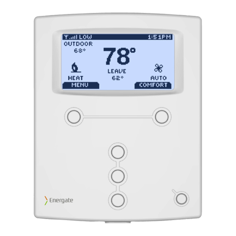
Energate
Energate Pioneer Z100 Smart Thermostat Specification sheet
Energate
Energate Pioneer Z100 Smart Thermostat Specification sheet
Energate
Energate Foundation User manual
Energate
Energate Foundation RM41F User manual
Energate
Energate Pioneer Z100 Smart Thermostat Specification sheet
Energate
Energate FZ100C User manual

Energate
Energate Foundation User manual

