Marlon 350 User manual

MARLON 350A AUTO CRIMPER
OPERATORS MANUAL

INTRODUCTION
Your new Marlon 350 Auto Crimper is designed
to increase your plastic spiral binding production.
The Marlon 350 is an inexpensive yet extremely
versatile tabletop machine. The Marlon 350 cuts and
crimps 6mm through 50mm coil, with an adjustable
binding length from 3.5-inches to 14-inches. The
Marlon 350 is capable of 50 cycles per minute, and
features a coil waste chute that uses standard plastic
grocery bags for clipping waste containment. The
Marlon 350 is an operator friendly machine that is
easy to set up, allowing for quick changeover from
one coil diameter to another. We are confident that
your new Marlon 350 Auto Crimper will be a
valuable asset to your plastic coil binding operation.
The following pages of this manual will cover
machine setup, operating procedures, and
troubleshooting your Marlon 350 Auto Crimper.

MARLON 350 AIR CONNECTIONS
COIL WASTE CHUTE
THE COIL WASTE CHUTE USES STANDARD PLASTIC GROCERY BAGS
FOR CLIPPING CONTAINMENT. PLACE THE HANDLES OF THE BAG
IN THE SLOTS ON BOTH SIDES TO HOLD THE BAG IN PLACE.
CONNECT THE FOOT
SWITCH TO THE CRIMPER
BY INSERTING THE CLEAR
TUBE INTO THE TOP PUSH
LOCK FITTING AND THE
BLACK TUBE INTO THE
BOTTOM PUSH LOCK
FITTING
QUICK CONNECT
ADAPTER PICTURED IS
NOT INCLUDED WITH
MACHINE.
USE A SIMILAR ADAPTER
THAT MATCHES YOUR
AIR SUPPLY.
MAIN AIR INPUT ¼” NPT
BULKHEAD FITTING
120 P.S.I. MAXIMUM AIR
PRESSURE
PLACE BAG
HANDLES IN
THESE SLOTS
TO HOLD BAG

BLADE SELECTION
The Marlon 350 Auto Crimper features interchangeable cutter
blades. Your Marlon 350 is shipped with the B-size cutter blades
installed. Use the following chart to determine what blade size is
required for the coil diameter you are crimping.
A-size blades: 6mm and 7mm coil (Sold separately)
Note: Oversized punch patterns (.248) or punch patterns with a large backstop (distance
from paper edge to hole) will not work well with the A – size cutter head.
B-size blades: 8mm through 35mm coil up to and including .093
filament diameter. 38mm through 50mm coil .103 filament
diameter with air cylinders in the C position
C-size blades: 18mm through 50mm coil (Sold separately)
The cutter blades and cutter head assemblies have been color
coded to reduce the chance of improper assembly.
1.) Universal parts of the cutter head assembly that are used for
all three sets of knives are marked white. These parts are used
all of the time.
2.) A-size parts of the cutter assembly are marked red.
3.) B-size parts of the cutter assembly are marked green.
4.) C-size parts of the cutter assembly are marked yellow.
Note: Some parts of the cutter assembly are marked with two
colors. These parts are used on two of the three cutter
assembly configurations.

CUTTER HEAD ASSEMBLY
Air Cylinder Clamp blade spring Clevis
Cutter blade assembly Clevis Pin
Air cylinder mounting bolt

B-SIZE CUTTER BLADE ASSEMBLY
NOTE: THE RIGHT CUTTER BLADE ASSEMBLY IS UP SIDE
DOWN. THE SAME FOUR BLADES ARE USED ON BOTH SIDES,
BUT THEY ARE INSTALLED IN EXACTLY THE OPPOSITE ORDER.
LEFT CUTTER HEAD
LEFT BASE PLATE
A, B & C – SIZE ANVIL
BLADE
B – SIZE .126” SPACERS
B – SIZE CUTTER BLADE
CLEVIS PIN & E CLIPS
B & C – SIZE-FORMING
BLADE
CLAMP SPRING
B & C – SIZE CLAMP
BLADE
.062” SPACER (B ONLY)
10-24 NYLOCK NUTS
RIGHT CUTTER HEAD
RIGHT BASE PLATE
CLAMP SPRING
B & C – SIZE CLAMP
BLADE
B – SIZE .126” SPACERS
B & C – SIZE-FORMING
BLADE
CLEVIS PIN & E CLIPS
B – SIZE CUTTER BLADE
A, B & C – SIZE ANVIL
BLADE
10-24 NYLOCK NUTS

Pictured above is the B-size cutter blade assembly.
The following information describes the changes needed to switch from the B to A-size and B to C-size
cutter assemblies. Refer to the color codes on page four to select the proper parts when changing from one
blade configuration to another. Refer to pages five and six for part descriptions.
Changing from B to A-size blades:
1.) Disconnect the air supply from Marlon 350.
2.) Remove the top cover from the machine.
3.) Unhook the springs from the studs on both sides.
4.) Remove the three 10-24nylock nuts from each side.
5.) The left clamp blade is nowfree.
6.) Remove the right anvil blade by lifting it straight up.
7.) Remove the left forming blade by lifting it straight up.
8.) Detach the right cutter blade fromthe clevis. (Use a straight blade screwdriver to pry the top
E clip off of the clevis pin. Slidethe clevis pin out of the clevis; the right cutter blade is now
free.)
9.) Remove the three .126” B-size spacers from each side.
10.)Remove the right forming blade by lifting it straight up. The right clampblade is now free.
11.)Detach the left cutter blade from the clevis. (See step 8 for details.)
12.)Leave the left anvil blade on, because it’s usedin all three setups.
13.)Reassemble the cutter blade assemblies in reverse order using the correct color-coded parts.
14.)Use the fifth .094” A-size spacerinstead of the .062” spacer on the left hand center stud.

A-KIT COIL GUIDE INSTALLATION
PICTURED ABOVE ARE THE COIL GUIDES INSTALLED ON
THE CUTTER ASSEMBLY. THESE GUIDES ARE ONLY USED
WITH THE A-SIZE BLADE CONFIGURATION. THE COIL
GUIDES ARE STAMPED “L” FOR LEFT AND “R” FOR RIGHT
AND ARE ALWAYS INSTALLED WITH THE LETTERS UP. YOU
HAVE TWO “L” GUIDES ONE MARKED
“L” AND ONE MARKED “L 6”. THE “L 6” IS USED FOR
6mm DIA. COILS ONLY.

CHANGING FROM “B” to “C” size blades
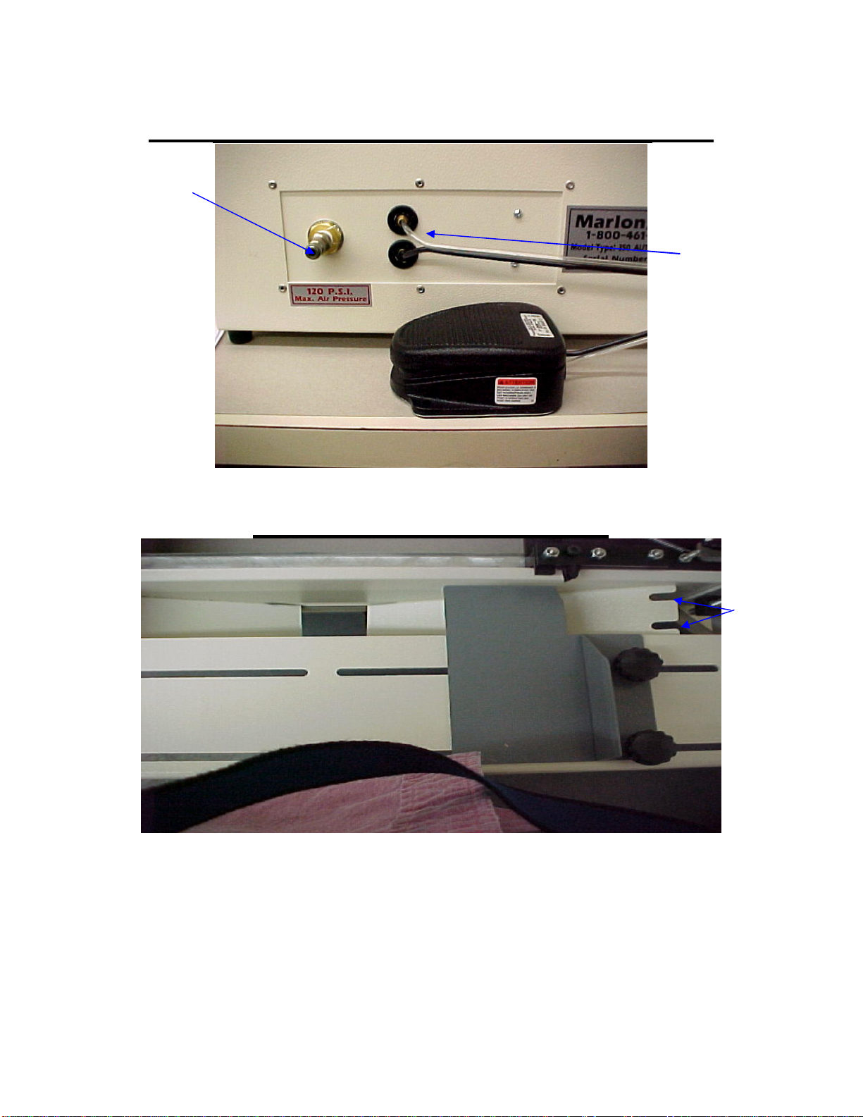
1.)Disconnect the air supply from Marlon 350.
2.)Remove top cover from machine.
3.)Unhook the springs from the studs on both sides.
4.)Remove the three 10-24 nylock nuts from each side.
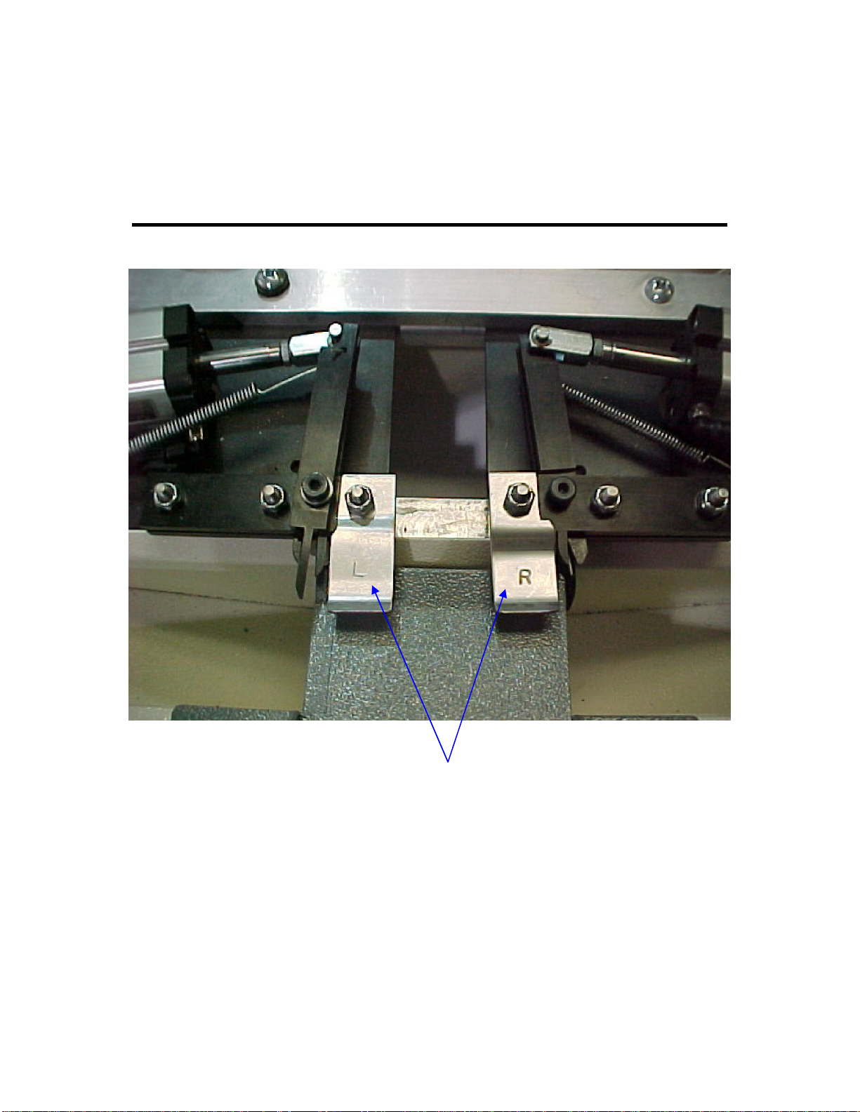
5.)The left clamp blade is now free.
6.)Remove the right anvil blade by lifting it straight up.
7.)Remove the left forming blade by lifting it straight up.
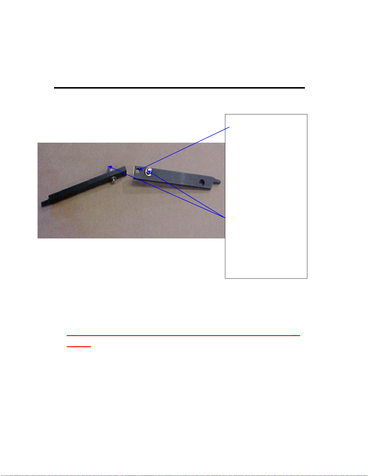
8.)Detach the right cutter blade from the clevis. (Use a straight
blade screwdriver to pry the top E clip off of the clevis pin.
Slide the clevis pin out of the clevis; the right cutter blade is
now free.)
9.)Remove the two126” B-size spacers from each side.
10.) Remove the right forming blade by lifting it straight up.
The right clamp blade is nowfree.
11.) Detach the left cutter blade from the clevis. (See step 8
for details.)
12.) Leave the left anvil blade on, because it’s used in all
three setups.
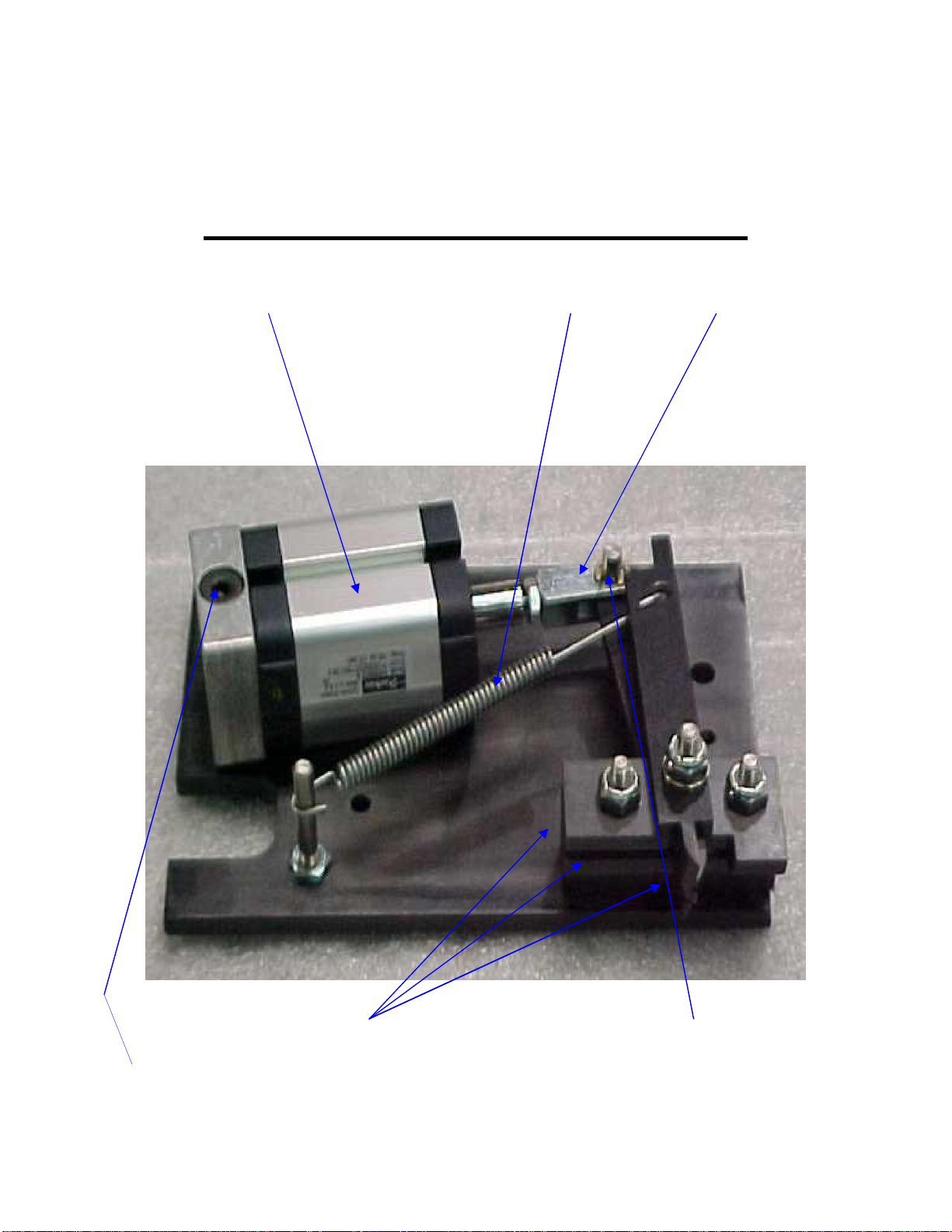
13.) Change the air cylinder position on both sides by
unscrewing the air cylinder mounting bolt (shown on page
5) now move the air cylinder to its correct hole position and
tighten the air cylinder mounting bolt. (See picture on page
10 for details.)
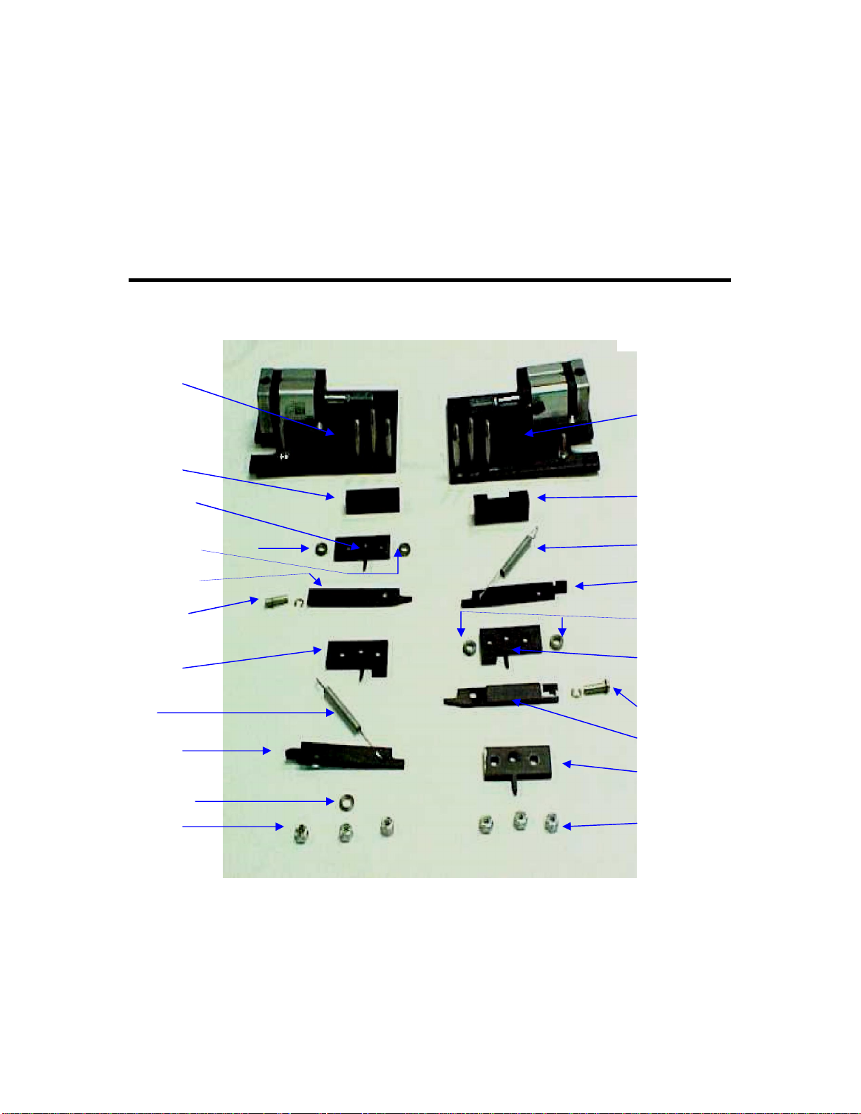
14.) Reassemble the cutter blade assemblies in reverse order
using the correct color-coded parts.
15.) Note: No spacer is used on the left-hand center stud
when using the C-size blade configuration.

C-CUTTER BLADE INSTALLATION
PICTURED ABOVE ARE THE C-SIZE CUTTER BLADES.
THE CLEVIS PINS INSTALLED ON THE C-CUTTER
BLADES ARE NEEDED TO PUSH THE CLAMP BLADES.
DO NOT CONNECT THE AIR CYLINDERS TO THESE
PINS. THE AIR CYLINDER SHOULD BE CONNECTED
TO THE C-CUTTER BLADES USING THE OPEN HOLE
AT THE REAR OF THE BLADE. THE CLEVIS PIN USED
TO DRIVE THESE BLADES IS IN THE AIR CYLINDER
CLEVIS. THE C-KIT FURNISHED WITH YOUR
MACHINE HAS THE PINS INSTALLED CORRECTLY.
CONNECT THE AIR
CYLINDER TO THE
HOLE AT THE REAR
OF C-CUT BLADES.
THE TWO CLEVIS
PINS INSTALLED ON
THESE BLADES ARE
USED TO ACTIVATE
THE CLAMP
BLADES.

AIR CYLINDER MOUNTING
POSITIONS
Mount the air cylinders in the top inside holes
for C-size blade configuration.
Mount the air cylinders in the bottom outside holes
for A and B-size blade configurations.

TABLE ADJUSTMENTS
Now that you have the correct blade configuration ready for the coil diameter
you are crimping you need to adjust the table height and cutter head spacing (width) for
your book. Refer to page 13 for table adjustment details.
1.) Loosen the two clamp knobs on the left-hand book guide; position the guide so your
book will be approximately centered on the machine. Re tighten the two clamp knobs.
2.) Using the same procedure position the right-hand book guide so it just touches the
right edge of the book. The book should layflat on the table between the book guides
and be able to slide in and out, but not side to side.
3.) Use a #3 Phillips screwdriver to loosen the two bolts located under the two access
holes in the top cover. The two cutter heads will now be able to slide from side to
side. Slide the two cutter heads so the cutter blades are close to the correct loop of
the coil at each end of the book.
4.) Make a rough adjustment on the table height by turning the two table height knobs.
Turn the knobs clock-wise to lower the table and counter clock-wise to raise the
table. Adjust the table height so the coil in the book is in the center of the cutter blade
assembly on both sides. The right side of the tablewill always be adjusted higher than
the left side.
5.) Adjust the two cutter heads from side to side until the coil in the book slides into the
cutter blades at the correct loop of the coil on each side of the book. Note: The air
must be plugged into the machine at this time so the cutter blade assembly is open.
6.) Make a finer adjustment to the table height so the coil in the book is properly
positioned in the center of the cutter blades.
7.) Make your final cutter head adjustments side to side if needed and then re tighten the
two bolts under the access holes of the top cover using the #3 Phillips screwdriver.
8.) Test crimp a book by depressing the foot pedal.
9.) Make your final table height adjustments if needed. Then repeat steps #8 and #9 until
the desired crimp is achieved.

TABLE ADJUSTMENT DETAILS
CLAMP KNOBS: TWO ON EACH BOOK GUIDE
TWO ACCESS HOLES
IN TOP COVER
TABLE HEIGHT
ADJUSTER KNOBS:
ONE ON EACH SIDE
BOOK GUIDES: ONE ON
EACH SIDE

TROUBLE SHOOTING GUIDE
PROBLEM SOLUTION
CRIMPER DOESN’T CYCLE VERIFY THAT AIR IS PLUGGED IN AND
TURNED ON
COIL IS BEING CRIMPED BUT NOT
CUT ADJUST TABLE HEIGHT FOR PROPER
ALIGNMENT

MARLON 350A AUTO CRIMPER
MARLON INC.
123 EAST 45TH STREET
BOISE, IDAHO 83714
Ph (800) 461-9301
Fax (208) 321-2796
This manual suits for next models
1
Table of contents