5. CHANGING THE SETTINGS
You can change the settings of the IR455 using a PC that runs under MS Windows.
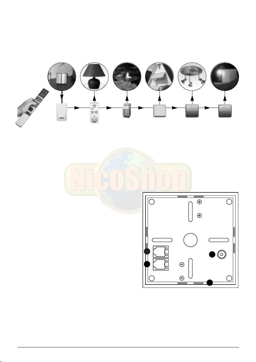
5.1. Connecting the device to the PC
Connect the PC cable to a free serial port (COM port) of your PC. The other end of the cable
can be connected to the ‘PC’ connection on the back of your IR455 (top connection).
5.2. Installing the software
• Place the CD-ROM in the CD-ROM drive. The software will start automatically. If the CD
does not start automatically, start the file setup.exe via your browser.
• Follow the instructions on your screen.
• When the installation is complete, choose: Programs > Marmitek > IR455.
• The program will start.
• Select the COM port (serial port) the IR455 is connected to and click GO.
If you do not know which COM port the device is connected to, choose a random port.
Choose e.g. COM port 1 and click ‘GO’. If COM port 1 is the right option, you will continue
to the next screen. If COM port 1 is not correct, you will receive the error message ‘Marmitek
IR455 not connected to CommPort 1’. Choose another COM port until you have found the
correct port.
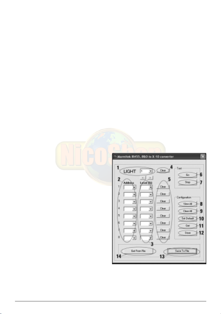
You will now see the following screen:
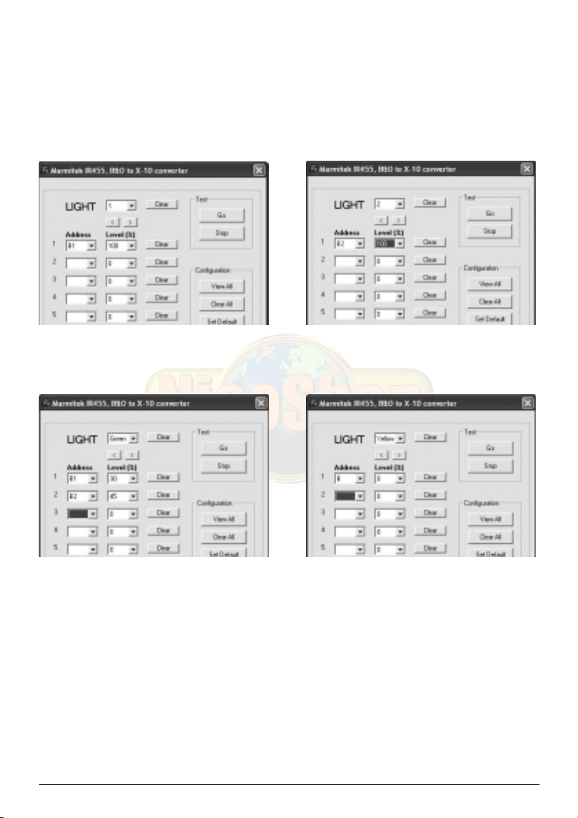
1. You are in the program screen for
button 1 (LIGHT - 1 - GO) of the BEO4
remote control. By pressing the >
button you will continue to the next
button. There are 20 possibilities: the
numbers 1-16 and the green, yellow,
red and blue buttons.
2. ADDRESS: With this option you can
indicate which X-10 modules should
be switched or dimmed when pressing
a button. You can have a maximum of
8 modules respond to one button
(atmospheric settings for e.g. reading
and watching TV).
3. LEVEL (%): With this option you can
set the brightness of the lights.
4. CLEAR: Clears all settings for this button. You can have a maximum of 8 modules
respond to one button (atmospheric settings for e.g. reading and watching TV).
5. CLEAR: This clears the setting per line.
6. GO: Simulates the GO button (e.g. LIGHT - 1 - GO) of the remote control. The command
is executed by the IR455.
7IR455