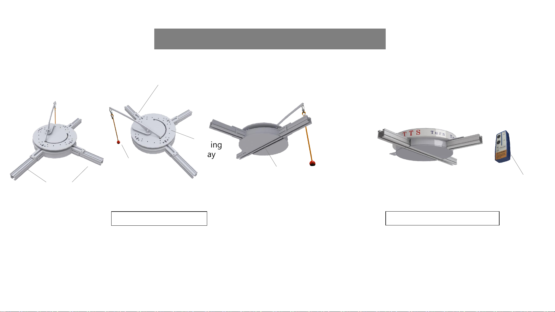
MARPE Gait Training System Assembly instructions

USER MANUAL GUIDE
Gait Training System
1. OVERVIEW
2. FEATURES
3. DETAILS
4. MANUAL
5. COMPONENTS
6. PRECAUTION

1. OVERVIEW
The Gait Training System (GTS) is composed of a walking
Rail, M-Sling, and M-Suit, and its main function is to
prevent falls.
GTS guides elders or patients with chronic disabilities to do
various functional activity of daily living in hospitals and
rehabilitation centers effectively.
The main uses of the GTS are in hospitals, rehabilitation
centers, elderly welfare centers, and facilities for the
disabled.
Group therapeutic exercise system can let many users can
have training at the same time.

2. FEATURES
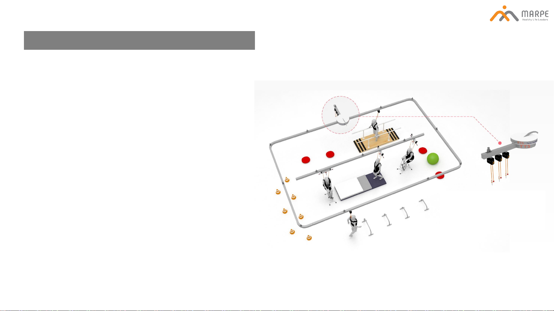
GTS consists of the manual and auto
matic Turn Terminal System which is
used to change the direction of the
user to not affect each other. Also, it
is used to place the unused Slings.
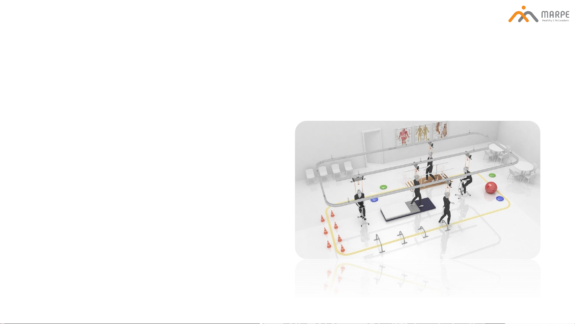
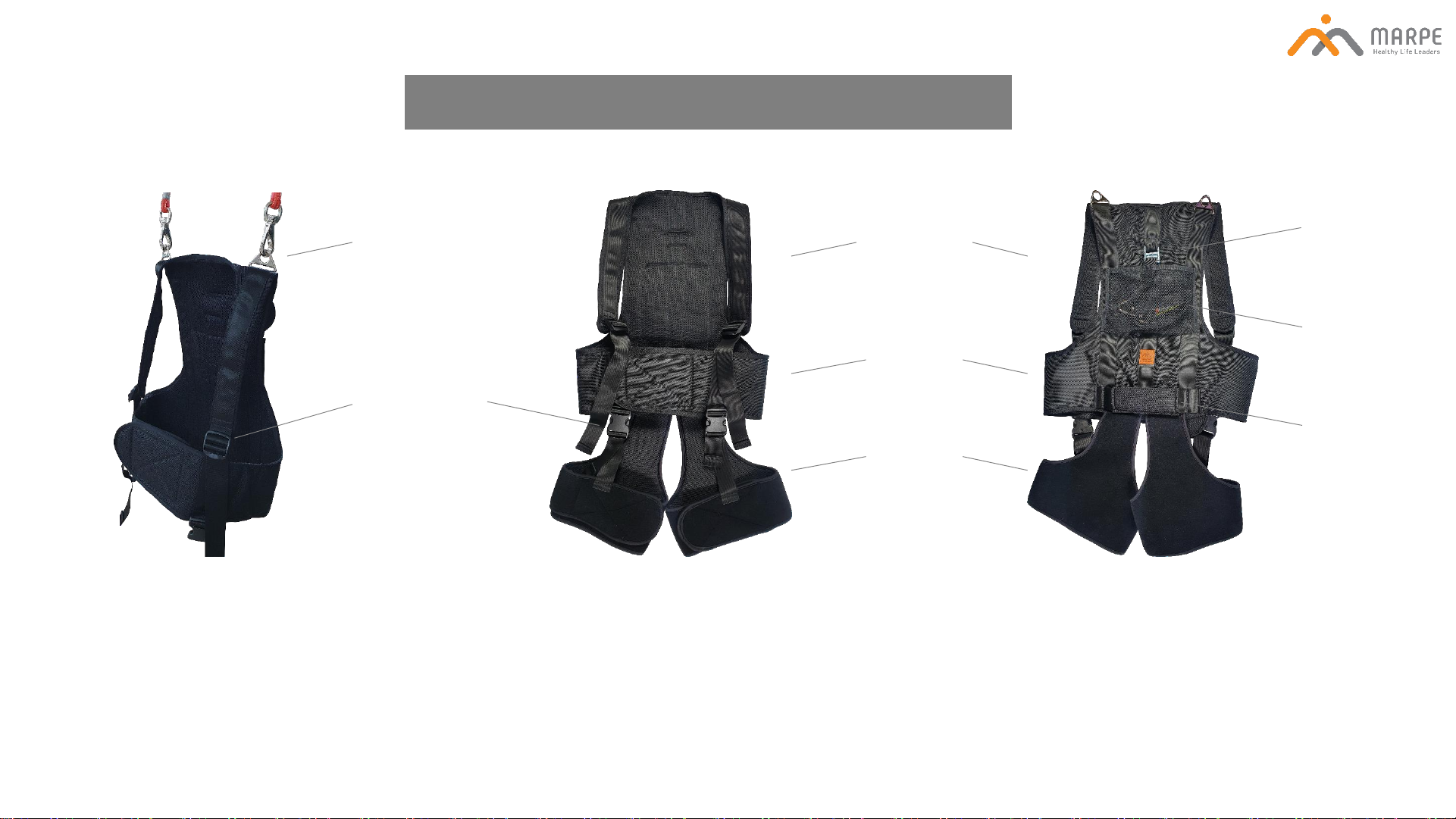
1. GTS is a unique method to train patients who cannot
walk independently caused by severe damages.
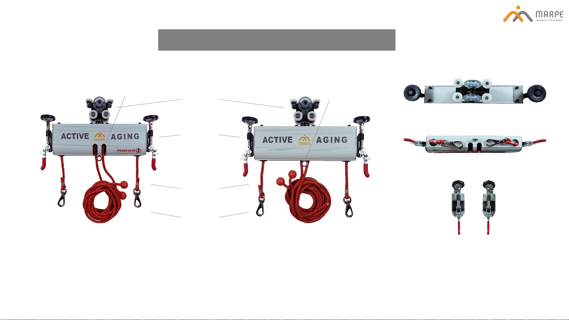
2. M-Sling system has the ability to fix easily, quickly, and
safely to any position on the walking rail.
3. M-Sling can hold a maximum load of about 200kg, so
even people with heavyweight can safely train.
4. M-Sling has the function of the Sling system, which
enables professional rehabilitation training as well as simple
gait training.
5. GTS develops the manual and automatic (remote control)
Turn Terminal System to change users at the center or other
outer rail direction without affecting each other. And not
only GTS can use at the same time but also to install
variously in small space and effective in time and space

2. FEATURES
6. GTS is available in both ceiling and stand type. The GTS
stand type can be installed in such places where ceiling
installation is not possible.
7. The basic size of GTS stand is 4m(L) x 2.5m(W) x 2.3m(H),
so can be used in a narrow space.
8. The GTS stand can make several rail shapes within its size.
For example, straight rail shape, a circular rail shape, or a
mixed shape of a round and straight rail.
GTS
stand
size:
4m(L)
x
2.5(W)m
x
2.3m(H)
/
300kg (Weight)

3-1 DETAILS of M-Sling
FRONT VIEW
Snap
Hook
Rope
357mm(Width) x 120mm(Height) x 65mm(Depth) / 5kg
Maximum load of M- Sling System : 200kg
Main Material : Aluminum, Steel, Polyester, Polyacetal, Urethane, Rubber
BACK VIEW
Locking
Roller
TOP VIEW
BOTTOM VIEW
SIDE VIEW
Hole Ring

3-2 DETAILS of Rail
FRONT & BACK VIEW
1,000mm(Width) x 104mm(Height) x 83mm(Depth) / 5kg - Per 1m
Main Material : Steel
SIDE VIEW
TOP VIEW
BOTTOM VIEW
Entire view of Rail

993mm(Width) x 110mm(Height) x 696mm(Depth) / 21kg
Main Material : Steel
Rope
Turning
way
Rail
way
Point
Grip
Rail
3-3 DETAILS of Turn Terminal
Manual Turn Terminal Automatic Turn Terminal
Remote

3-4 DETAILS of M-Suit
FRONT VIEW
Main Material : Neoprene, Air-mesh, Webbing, Plastic, Steel
BACK VIEWEntire view of M-Suit
Waist
Belt
Thigh
Belt
Shoulder
Strap
Triangle
Hook
Adjustable
Buckle Waist
Strap
Assist
Safety
Strap
Rope
Pocket

4-1 MANUAL of M-Sling
How to use M-Sling System
1. Releasing and Lowering Ropes
(a) Stand in front of the device, hold the Adjusting Ropes (middle) in
one hand and Main Ropes (connected straps with hook) in other hand
(b) Gently pull forward the Adjusting Ropes from Cleat to move the ro
pe freely and pull the Main Ropes straight down to the desired height
2. Locking Ropes
(c) Fix the Adjusting Ropes to the Cleat, so they hang straight down;
the ropes will lock when a load is placed on them
3. Raising Straps
(d-e) Pull the Adjusting Ropes straight down until the straps are at the
desired height
(f) The straps will lock when a load is placed on them
(a) (b) (c) (d) (e) (f)

4-2 MANUAL of fixing M-Sling to the Rail
①When securing the M-Sling to the rail, position the M-Sling horizontally to the rail.
②Hold the red fixing levers on both sides of the M-Sling and lift up all the way to the sides to fix it.
③On the contrary, when releasing the fixing, hold the red fixing lever in the order of ③→ ①and lower it all the way down,
- If the fixing device is not lowered all the way down, it may cause jamming in the rail.
- Fixing device should always be used on both sides at the same time.
①③Unfixed state 고정이 되어있는 상태
Fixed state
②

4-3 MANUAL of Turn Terminal
①Hold the Rope of the Turn Terminal
②Pull the rope straight down
③Rotate the Point Grip in desired place
④Release the rope
① ② ③ ④

4-4 MANUAL of M-Suit
①First, a suit is placed on the user’s
shoulders and stands in front of
him/her, sticking out one leg to
support the body.
②The waist belt should be
located below the middle of the
waist and aligning the belt inward.
③Pull the inner belt tight,
then stick the outer belt firmly
on top of it.
① ② ③

4-4 MANUAL of M-Suit
④ Adjust the shoulder strap to fit the user’s
body type. (Slightly raised the Adjustable
Buckle with one hand and pull down the
Webbing belt for smooth adjustment.)
⑤The lower part of the suit
is filled in the middle of the
thigh with Velcro.
⑥Wearing the suit is completed
by pulling the front length
adjustment strap down tightly.
④ ⑤ ⑥

4-4 MANUAL of M-Suit
Wearing the suit correctly

4-4 MANUAL of M-Suit
How to attach the multi-strap to the M-Sling
Attach the non-elastic assist rope of 30 cm to
the M-Sling main rope, as shown in the figure.
Hang and hold the multi-strap as
shown in the figure.

5. COMPONENTS
③Multi Strap(2ea) :340mm x290mm
④Rope 30cm(2ea) : ∅8 x 300mm
⑤Elastic 130cm(1ea) : ∅7x 1300mm
①M-Sling(1ea) : 357mm x 120mm x 65mm
②M-Suit(1ea)
⑥Pulley(1ea) : 155mm x ∅ 48mm
① ②
③
⑥
④
⑤
⑦Rail
⑦

PRECAUTIONS FOR USE
Periodically check that the M-Sling system is well secured
to the rails.
Noise can be prevented when using the M-Sling system by
applying grease to the roller wheels periodically.
Periodically check that the ropes of the M-Sling system are
in good condition.
Do not hang on or place weight on only one rope of the
M-Sling system.
Raise the brake lever all the way up when securing the M-
Sling to the rail, and lower it all the way down when
moving.
If the rope doesn’t fix in the cleat of the M-Sling system,
stop using the M-Sling system and please contact us.
STORAGE AND MAINTENANCE
Store the M-Sling System in a cool and dry place and clean
them with a soft dry cloth. The working temperature should
be 0 ~ 45˚C(32 ~ 113˚F). Working in cold/hot environments
or highly humid areas will reduce the durability.
CONTACT US
If you need to repair a product under warranty, please send a
detailed explanation describing the problem to
Find more information on the dedicated website www.
marpe2000.co.kr
6. Others

Marpe. All Rights Reserved.
This manual suits for next models
1
Table of contents
Popular Fitness Equipment manuals by other brands

Crane
Crane FLX-PU-01 user manual

ICON Health & Fitness
ICON Health & Fitness Pro-Form Trainer 12.0 PFTL99721.0 user manual

Energetics
Energetics CT 12.5 Ergometer owner's manual

Digi 1st
Digi 1st T-5020 quick start guide

Weider
Weider Pro 9450 Manual Del Usuario

New Image
New Image Maxi-Glider 360 Assembly and user's guide

Keys Fitness
Keys Fitness StrenghtTrainer ST-OBA2 owner's manual

Goalsetter Systems
Goalsetter Systems GS Wall Mount Installation & owner's instructions

Skandika
Skandika Vinur manual

Crivit
Crivit 78680 Instructions for use

Paramount Fitness
Paramount Fitness FT-150A Assembly manual

Robotouch
Robotouch VibraSlim Plus Body Shaper With Watch-Pink Operation instructions