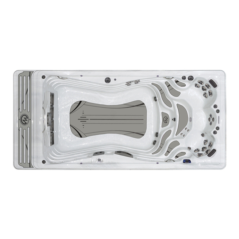
Marquis EPIC User manual

1
We sincerely hope your spa life is a pleasant experience. If problems should
arise, contact your authorized Marquis Spas®dealer. Or contact Marquis Corp.
at any of the following:
Email: service@marquiscorp.com
Web: www.marquisspas.com
Marquis Corp.
596 Hoffman Road
Independence, OR 97351, USA
This manual is provided to enhance your enjoyment of your spa and to prevent
non-warranty situations. It is your sole responsibility to read, understand and
comply with the instructions in the owner’s manual. Please save your original
sales receipt for reference in case of a future warranty claim. Failure to use,
maintain or install the spa in compliance with this owner’s manual could result in
loss of warranty coverage.
PRODUCT REFERENCE
SERIAL NUMBER LOCATION
You will find the serial number in the equipment area.
PLEASE FILL OUT AND KEEP FOR FUTURE REFERENCE
Name of Purchaser________________________________________________
Date of Purchase _________________________________________________
Address ________________________________________________________
City _____________________Country/Province_________________________
Postal Code _____________________________________________________
Spa Model/Colour _________________________________________________
Spa Serial No.____________________________________________________
Pack Serial No.___________________________________________________
Dealer’s Name ___________________________________________________
Dealer’s Address _________________________________________________
City _____________________Country/Province_________________________
Postal Code _____________________________________________________
Telephone _______________________________________________________
Every effort has been made to ensure the accuracy of this manual. However,
Marquis Spas®reserves the right to improve its product without notice. This
could create a minor variation between this manual and the actual product you
receive. We apologize for any inconvenience this may cause.
SEPARATE WASTE COLLECTION
This symbol indicates the need for separate waste
collection of electronic and electrical equipment.
Please do your part in protecting the environment and
human health by reusing and recycling used electronic
equipment whenever possible. Please do not dispose
of such equipment as unsorted municipal waste. This
product was put on the market after August 13, 2005.
OWNER’S MANUAL INDEX
IMPORTANT SAFETY INSTRUCTIONS
All Spa Models ........................................................................................ 2
Personal Safety...................................................................................... 2
INSTALLATION INSTRUCTIONS
Location.................................................................................................. 3
Filter Cartridges...................................................................................... 3
Electrical Requirements.......................................................................... 4
STARTING YOUR SPA ...............................................................................4-5
SPA CONTROL OPERATION
Euphoria, Mirage, Promise, Rendezvous, Resort,
Reward, Spirit, Wish................................................................................ 6-7
Epic, Show... ........................................................................................... 7-8
Adagio™Audio System........................................................................... 9
Aquavision Unit........................................................................................ 9
EQUIPMENT DIAGRAMS
All Models…………………....................................................................... 10
SPA MODELS ...............................................................................
Epic..........................................................................................................11
Euphoria.................................................................................................. 11 8
Mirage...................................................................................................... 12
Promise…………………………………………………………………….. 13
Rendezvous............................................................................................ 13
Resort……………………………………………………………………….. 14
Reward.....................................................................................................14
Show........................................................................................................15
Spirit.........................................................................................................15
Wish…………………………………………………………………………….16-17
TROUBLESHOOTING................................................................................. 18
LCD Diagnostic Messages ......................................................................18
Maintenance Reminders.......................................................................... 18
MAINTENANCE........................................................................................... 18-19
MARQUIS SPA CARE................................................................................ 19-20
Water Care Troubleshooting........................................................ ……… 20
OWNER’S PROTECTION PLAN............................................................... 21
ADAGIO™ AND AQUAVISION LIMITED WARRANTY.............................. 22
WARNUNG: Bevor Erhaltenzugriff auf Terminale, müssen alle
Versorgungskreisläufe abgeschaltet werden.
WARNING: Before obtaining access to terminals, all supply circuits must be
disconnected.
Marquis Spas®is fully compliant with the European Union Council Directive
2002/95/EC (restriction of Hazardous Substances –RoHS).
Additionally, products are marked according to Annex IV of Council Directive
2002/96/EC (Waste Electrical and Electronic Equipment –WEEE) which
addresses the handling of products at the end of their useful life.

2
SAFETY INSTRUCTIONS
The following instructions contain important safety information. We strongly
encourage you to read and apply them.
IMPORTANT SAFETY INSTRUCTIONS
WHEN INSTALLING AND USING THIS ELECTRICAL EQUIPMENT, BASIC
SAFETY PRECAUTIONS SHOULD ALWAYS BE FOLLOWED, INCLUDING THE
FOLLOWING:
1. READ AND FOLLOW ALL INSTRUCTIONS.
2. WARNING: To reduce the risk of injury, do not permit children to use this
product unless closely supervised at all times.
3. DANGER: RISK OF CHILD DROWNING. Extreme caution must be
exercised to prevent unauthorized access by children. To avoid accidents,
ensure that children cannot use the spa or hot tub unless they are
supervised at all times.
4. WARNING: Disconnect all supply circuits before obtaining access to the
terminal.
5. A ground/earth terminal is provided on the terminal block located on the
outside of the control box. To reduce the risk of electric shock, connect this
terminal to the grounding/earth terminal of your electrical service or supply
panel with a continuous green/yellow, insulated copper wire. The wire must
be equivalent in size to the circuit conductors supplying the equipment. In
addition, a bonding terminal (pressure wire connector) is provided on the
outside of the control box for bonding to local ground/earth points. To
reduce the risk of electric shock, this connector should be bonded with a
No. 8 AWG (8.42mm2) solid copper wire to any metal ladders, water pipes,
or other metal within five feet (1.5m) of the spa to comply with local
requirements.
6. Your spa uses ground fault circuit interrupters (GFCIs) or residual current
devices (RCDs) in the electrical sub-panel. Before each use of the spa and
with the unit operating, press the Test button on each breaker. The switch
should click over to the “Trip” position. Wait thirty seconds and reset each
RCD breaker by switching it completely off and then completely on. The
switch should then stay on. If either of the interrupters does not perform in
this manner, it is an indication of an electrical malfunction and the possibility
of an electric shock. Disconnect the power until the fault has been identified
and corrected.
7. Install the spa so proper drainage is provided for the compartment
containing the electrical components.
8. DANGER: RISK OF ELECTRIC SHOCK. Do not permit any appliance,
such as a light, radio, telephone, or television within 1.5m of the spa or hot
tub.
9. WARNING: TO REDUCE THE RISK OF INJURY.
•The water in the spa should never exceed 40° C. Water temperatures
between 38° C and 40° C are considered safe for a healthy adult. Lower
water temperatures are recommended for extended use (exceeding 10
minutes) and for young children.
•Since excessive water temperatures have a high potential for causing
fetal damage during the early months of pregnancy, pregnant or possibly
pregnant women should limit spa water temperatures to 38° C.
• Before entering a spa, the user should measure the water temperature
with an accurate thermometer since the tolerance of temperature-
regulating devices may vary as much as +/- -3° C.
•The use of drugs, alcohol, or medication before or during spa use may
lead to unconsciousness with the possibility of drowning.
•Persons suffering from obesity or with a medical history of heart disease,
low or high blood pressure, circulatory system problems or diabetes
should consult a physician before using the spa.
•Persons using medications should consult a physician before using a spa
since some medication may induce drowsiness while other medication
may affect heart rate, blood pressure, and circulation.
10. DANGER: TO REDUCE THE RISK OF INJURY TO PERSONS. Do not
remove the suction fittings.
11. DANGER: RISK OF INJURY. Never operate a spa if the suction fitting(s)
are broken or missing. Never replace a suction fitting with one rated less
than the flow rate marked on the original suction fitting. The suction fittings
in the spa are sized to match the specific water flow created by the pump.
Should the need arise to replace the suction fittings or the pump, be sure
that the flow rates are compatible.
12. DANGER: Children are especially sensitive to hot water. At no time should
children have unsupervised access to the spa. Children must not be
allowed to climb onto the spa cover. All Marquis Spas are equipped with a
locking safety cover. Always lock the child resistant locks after using the
spa for your children’s safety.
13. CAUTION: To reduce the number of airborne bacteria in an enclosed spa
area, proper ventilation must be provided.
14. WARNING: The design and construction of this spa are in accordance with
all applicable regulations. Modifying or adding spa components may affect
proper spa functioning, and may void the compliance markings.
15. SAVE THESE INSTRUCTIONS.
PERSONAL SAFETY
Prolonged immersion in hot water can result in HYPERTHERMIA, a dangerous
condition which occurs when the internal temperature of the body reaches a
level above normal (37°C). The symptoms of hyperthermia include dizziness,
fainting, drowsiness, lethargy, and a body temperature above 37°C. The
physical effects of hyperthermia include unawareness of impending hazard,
failure to perceive heat, failure to recognize the need to exit the spa, physical
inability to exit the spa, fetal damage in pregnant women, and unconsciousness
resulting in a danger of drowning.
WARNING: The use of alcohol, drugs, or medication can greatly increase the
risk of fatal hyperthermia in hot tubs and spas.
Persons taking medications which induce drowsiness such as tranquilizers,
antihistamines, or anticoagulants should not use the spa. Pregnant women and
persons with a medical history of heart disease, diabetes, or high blood pressure
should consult a physician before using the spa.
PERSONAL SAFETY DOS:
• Be sure your spa is connected to the power supply correctly –use a
licensed contractor.
•Disconnect the spa from the power supply before draining the spa or
servicing the electrical components.
•Test the RCD monthly.
•Test the water temperature with your hand before entering the spa to be
sure that it’s a comfortable temperature.
•Do not use the spa if water temperature is outside of set temperature.
•Remember that wet surfaces can be very slippery. Take care when
entering and exiting the spa.
•Use the safety cover when the spa is not in use, whether it is empty or full
of water.
•Keep the water clean and sanitized with correct chemical care.
•Turn on the jets when adding ANY spa water chemicals.
•After running the pump for three consecutive 15 minute periods (if so
desired), allow for a 30 minute cool-down period.
•Clean the filter cartridge(s) monthly to remove debris and mineral buildup
which may affect the performance of the hydrotherapy jets, limit the flow,
or trip the high limit thermostat which will turn off the entire spa.
PERSONAL SAFETY DON’TS:
•Don’t use the spa with the equipment compartment door removed.
•Don’t use the spa for long periods of time at water temperatures in excess
of 40°C.
•Don’t allow the jet pump(s) to operate for an extended period of time with
the cover in place. Extended pump operation will cause a slow heat
buildup due to water friction. The spa equipment controls are equipped
with a built-in safety timer that will automatically shut off the jet pump(s)
after 15 minutes of continuous operation should it have been left on
inadvertently.
•Don’t operate the spa at any time with the filter cartridge(s) removed.
•Don’t lift or drag the cover by using the tie-down straps or cover skirting;
always lift and carry by using the external handles.
•Don’t store chemicals in the spa’s equipment compartment.

3
INSTALLATION INSTRUCTIONS
LOCATION
For your portable spa to function properly and safely, it must be located on a
hard, flat, level surface. Inground spas require special installation techniques
and should be planned in conjunction with your authorized Marquis Spas®
dealer. Improper installation can result in structural damage to the spa and the
voiding of your spa warranty. Items to discuss with your dealer include: local
construction codes, electrical service requirements, serviceability of equipment,
existing underground obstructions such as gas, water, and telephone lines,
safety measures such as fences and locks, and visibility of the spa installation
from the home, street, and neighbours.
•Do not shim your spa. If your pad is not level you must pour a top cap:
contact a professional.
•Allow for sufficient water drainage around the spa to help preserve the
equipment and support structure. This includes indoor installations.
• A filled spa can weigh up to 2268 Kg and the location must support the
weight of the filled spa.
• Locate the equipment compartment where it will be accessible. Your spa
MUST be installed to permit access for servicing the equipment above and/or
below any decks or floors. Access is essential and must allow adequate room
for service. To facilitate repairs, Marquis Corp. or its agent may require
access to spa equipment. It is your responsibility to provide unencumbered
access. See spa diagrams for location of power supply.
• Leave access to the circuit breakers in the sub panel.
•Be sure the spa is level and in the final position BEFORE filling with water.
Check for power cords, tools, and hoses that may be caught underneath the
spa.
•Do not apply power to the spa before it is completely filled with water.
Damage to the pumps, heater and sensors may result.
•IMPORTANT: DO NOT LET AN EMPTY SPA REMAIN EXPOSED TO
DIRECT SUNLIGHT. Spa surface temperatures can reach in excess of 82°C
if left exposed to the sun. Significant damage can occur if this is allowed to
happen, including warping and blistering of the surface and components.
Damage that occurs as a result of this exposure is not covered under the
warranty.
• CAUTION: Never try to move a spa that has not been fully drained. To do so
could result in damage to the spa and physical injury to the mover.
•Cracks in the spa surface, exterior siding or DuraBase due to improper
transport or support of the spa are not covered under the warranty.
OUTDOOR AND PATIO INSTALLATION
To install the spa outdoors, we recommend a reinforced concrete pad at least 10
cm thick. The reinforcing material should be grounded per electrical codes.
If you place the spa on the ground, even temporarily, place the spa empty of
water on concrete pavers under the entire bottom of the spa. The concrete
pavers should be at least 5 cm thick and level across the entire surface. The spa
will inevitably settle and become out of level on this surface, thus it is important
to get the spa onto a solid foundation as soon as possible.
INSTRUCTIONS FOR PREFABRICATED SPA PADS
If you are using a prefabricated spa pad for a foundation, please use the fol-
lowing guidelines:
1. Designate the area where the spa is to be installed. Please make sure the
ground is flat and level.
2. Using 2”x 6” weather resistant lumber and 3” outdoor deck screws, build a
frame large enough for the prefabricated spa pad to fit inside with minimum
1” clearance on all sides.
3. Install the frame in the area that has been leveled.
4. Using pea gravel, please fill the frame to the top.
5. Lay a straight piece of lumber across the frame and level any high spots in
the gravel by pushing the straight lumber across the frame. Fill in any low
areas with more gravel and re-level using the straight piece of lumber.
6. Compact the gravel to make the surface is hard and flat. You may need to
add more gravel to bring the level back up to the top of the frame. If so,
please re-level and re-compact until you have a hard, flat level surface that is
even with the top of the frame.
7. Place the prefabricated spa pad on top of the gravel. Please be careful not to
disturb the hard, flat, level surface.
8. Please make sure no portion of the spa pad is sitting outside or on top of the
framing.
9. Place the spa on top of the pad and fill the spa with water.
DECK INSTALLATION
Be sure the deck can support the weight of your filled spa by checking the
deck’s maximum load capacity. Consult a qualified building contractor or
structural engineer. Minimum requirement is 45.36 Kgs. per 9.3 cm.
INDOOR INSTALLATION
There are special requirements if you place your spa indoors. Flooring material
must provide adequate traction when wet. Proper drainage is essential to
prevent water pooling. To avoid increased humidity, you need to provide proper
ventilation to the area. The addition of a ventilation system is recommended.
SHUT-OFF VALVES
Your spa is equipped with shut-off valves (see EQUIPMENT DIAGRAM) that
shut off the water flow to the equipment system for authorized Marquis Spas®
dealer service. At times, a new spa or one that has recently been serviced may
have the shut-off valves partially closed which can restrict the water flow and hinder
jet performance. Be sure the valves are fully open.
FREEZE PROTECTION
When a freeze condition is detected (which occurs when the temperature in the
heater housing drops to 13°C), the jet pump(s) is automatically activated. In
areas with extremely cold winter conditions, your spa should be fine as long as it
is left running at normal operating temperatures. If you plan to turn the spa off,
follow the instructions in this manual (see SUSPENDED USE OR
WINTERIZING YOUR SPA).
OVERHEATING
In the case of extended hot weather, the spa water temperature may reach and
maintain 40°C to 41°C or higher. This is due to the ambient temperature and the
full insulation in the spa cabinet. You may have the option of shortening the
pump-run time. (See SPA CONTROL OPERATION for available options.)
FILTER CARTRIDGE(S)
Your portable spa features one or two Vortex filters.
Filter cartridges and filter lids are warranted to be free of defect at time of
delivery and do not qualify for labor coverage under the warranty. These parts
can be purchased or exchanged at your authorized Marquis Spas®dealer.
NOTE: It is very important that the components of these filtration systems be
installed properly in the proper part of the spa.
1. Hold the Vortex filter cartridge and center it in the opening of the filter
housing.
2. Use the filter handle and turn the filter cartridge clockwise to screw it in
place. (Use caution not to over tighten as damage may occur to threads
and is not covered under warranty.)
3. Grasp the edge of the Vortex skimmer lid, gently place the tray in
position resting the center point in the groove.
SUCTION GUARDS
The suction fitting(s) in the footwell of your spa is an opening through which the
jet pump(s) draws water. Suction fittings are equipped with a safety guard.
Suction through the fittings can be strong. The safety guard(s) must remain in
place and undamaged. A fitting with a damaged guard(s) can be dangerous,
especially to small children or people with long hair. Should any part of the body
become drawn to a fitting, immediately turn the jet pump(s) off. Long hair should
be restrained. Never allow long hair to float freely in the spa. Replace any
missing or damaged suction guard(s).
NOTE: It is normal for the flow rates of the suction fittings to vary from strong to
barely noticeable.
ELECTRICAL REQUIREMENTS
It is the responsibility of the spa owner to ensure that all electrical connections
are made in accordance with all electrical codes in effect at the time of
installation including proper bushings (at least 1 mm in diameter) at the spa
control and at the appliance openings. The recommended spa operating

4
environment is -5°C to +45°C, at 20-80 percent of relative humidity. Fuses are
covered to be free of defect at time of installation only.
Electrical Supply:
Insert the incoming electrical service line through
one of the access holes on either side of the spa
base (remove plastic plug). Then insert the service
through the electrical access hole of the control
box (see diagrams).
A pressure wire connector is located on the exterior of the control box. If the
installation includes a common bonding grid (reinforced concrete slab,
ground/earth plate beneath the spa, or any metal water pipe connection), this
pressure wire connector should be bonded to any metal ladder, water pipe, or
other metal, within 1.5 m of the spa and in accordance with pertinent electrical
codes.
220-240V AC, 50 Hz:
Connections shall be made in accordance with the wiring diagram found on the
inside of the control box cover. Connections should be made with copper
conductors only –aluminum wiring should not be used with this system. All
conductors, circuit breakers, and/or fuses must be sized in accordance to the
input ratings shown below:
220-240 V AC, 50 Hz:
• Permanently connected
• Rated 220-240V AC –50 Hz
• One and two pump spas are rated 16A for low amp setting (heater off
during high-speed) and 32A for high amp setting (heater on during high-
speed).
Improperly wired spas can cause irreversible damage resulting in blown fuse
and melted terminal block, and to other electrical components. Also, damage
caused to components or equipment caused by high or low voltage, brown outs
or electric surges is not covered under warranty.
Electrical Service Connections at Terminal Block, Inside Spa Controller:
The spa must be supplied through a single MCB with a certified residual current
device (RCD) with a rated current trip not exceeding 30 mA. Means for spa
disconnection from supply must be incorporated in the fixed wiring.
Recommended supply conductor nominal cross sectional area is 4mm2 for 16A
rating, 6 mm2 for 32A rating.
NOTE: If the power cord on any piece of electrical equipment, such as a jet
pump or ozone generator, becomes damaged, do not use the spa until the cord
has been repaired. Consult your authorized Marquis® dealer for assistance on
such repair.
230V 1x16A
230V 2x16A
230V 3 x 16A

5
Improperly wired spas are beyond Marquis Corp. control and are not covered
under the warranty. Other items beyond Marquis Corp. control include, but are
not limited to, damage resulting from: improper connections; accidents; failure to
follow procedures and instructions defined in the Marquis Spas® printed
instructions; cleaning agents; and natural occurrences including but not limited
to rodent or insect infestation, mold, lightning and other acts of nature.
STARTING YOUR SPA
START-UP PROCEDURE
Your spa is equipped with solid-state Comfort Controls specific to your spa
model. (See SPA CONTROL OPERATION for your specific spa model.)
To start your spa, you need a spa water test kit or test strip and an underwater
thermometer. It is important to follow each of these steps when starting your spa.
Once you have completed the following steps, refer to the instructions in your start-
up kit for proper start-up water maintenance, or see MARQUIS SPA CARE.
NOTE: Your spa has been filled and test-run at the factory. The first time your
spa is filled with water, some discoloration from residual test water may appear.
This will disappear when the spa is completely filled and the filtration system is
functioning.
WARNING: Spa must be completely filled with water before turning on power.
Test the water for the proper chemical balance and adjust as necessary.
Marquis SpaCare™products are recommended. (See WATER TREATMENT.)
PROPER CHEMICAL BALANCE IS IMPORTANT for your safety and the
longevity of your spa.
In the case of relocating your spa, it is imperative to follow the instructions in the
owner’s manual. These instructions must remain with the spa. Damage caused
by relocating spa is not covered under warranty.
THERAPY PUMP(S)
Start-up procedure for all models
1. Place spa on a hard, flat, level surface. Make sure the power supply is
off.
2. Make sure the suction guard(s) in the footwell are in place and
undamaged.
3. Open the equipment door. Tighten all disconnects and open all shut-off
valves.
NOTE: Keep the drain valve closed at all times except when draining the spa
(do not rely on the cap to stop the flow of water). Not doing so could
result in damage to the drain valve due to freezing water.
4. Install filter cartridges. (See INSTALLATION INSTRUCTIONS, Filter
Cartridges.)
5. Fill the spa with water to two-thirds of the way up the Vortex skimmer
openings.
The use of a Fill Filter is recommended, especially in areas with high
mineral content in the water.
6. Turn the power on.
WARNING: Spa must be completely filled with water before turning on power.
7. Allow the spa to circulate on high-speed (see SPA CONTROL
OPERATION) for four to five minutes to discharge air from the
plumbing system. Do not expect hot water immediately from the jets;
the heater will take several hours to heat the water.
8. Your spa is now in a “Priming” mode and a “Priming Mode” message
displays in the LCD window of the control panel. While in this mode the
spa appears idle, which lasts approximately four to five minutes if not
exited manually. To exit manually, press the JETS 1 pad.
9. At this time, the spa should have water flowing from the jets. If the
pump has not primed and the water is not flowing from the jets after
two minutes, TURN OFF POWER TO THE SPA and vent air from the
pumps by slightly opening the pump unions located behind the
equipment door. After turning the power on again, the spa initiates a
new priming mode. Repeat steps above.
10. The system requires approximately two minutes of water flow to
determine the water temperature. After two minutes of water flow, the
temperature is displayed as actual water temperature. After you have
manually exited the priming mode (or allowed the spa to automatically
exit), the LCD window momentarily displays 38°C and then the display
switches to - - °C.
11. The factory default setting for water temperature is 38°C. Use the
TEMP pads on the control panel to set the water temperature to the
desired level. (See SPA CONTROL OPERATION.) Your spa heats at
the rate of approximately 3°C per hour.

6
Test the water for the proper chemical balance and adjust as necessary.
SpaCare products are recommended. (See WATER TREATMENT.) PROPER
CHEMICAL BALANCE IS IMPORTANT for your safety and the longevity of your
spa.
DURACOVER™
When the spa is not in use, the cover should be kept on the spa to retain the
water’s heat and to keep out dirt, leaves, etc.
For your safety and convenience, the cover is equipped with adjustable straps,
safety locks, and handles. Use the exterior handles to remove and replace your
cover. Never attempt to open or remove the cover by grasping or pulling on the
cover skirting or cover lock straps as the skirting will tear.
Marquis suggests you use the safety locks to help keep out unintended users
and prevent covers from being blown off in windy conditions. The cover and
retractable cover system are not recommended for use in wind conditions
reaching above 40 km/h. If your spa is located in an area susceptible to high
winds, additional cover lock straps may be necessary to minimize cover
damage.
NOTE: Marquis’ exclusive DuraCover is designed for optimum protection of the
spa shell. Using an aftermarket cover will not provide the same protection and
will void the shell warranty.
Open the spa cover:
1. Unfasten all cover lock straps.
2. Place one hand under the cover skirting, between the spa and cover,
to break the cover’s vacuum seal. Do not use cover handles to break
vacuum seal.
3. Fold the front half of the cover over onto the back half.
NOTE: Unlock and release all cover locks before attempting to open cover.
Damage caused by attempting to open the cover while locked or by wind is not
covered under warranty. Do not walk, stand, climb, or sit on the vinyl cover or
retractable cover system. Do not use hard, sharp, or metal objects, such as a
windshield scraper, to remove ice. Such objects can cut, mar, or puncture the
cover’s vinyl surface.
Close the spa cover:
1. Slide folded cover onto one half of spa.
2. Unfold the cover by lifting the handle located on the top (front) half of
the cover. Allow the unfolded half to fall down onto the spa.
3. Secure the cover lock straps to the spa and lock them.
NOTE: When opening a cover with a cover removal mechanism, use one of the
manufacturer’s recommended methods. Do not attempt to open the cover in any
other way. Damage caused by improper opening or closing of the cover is not
covered under the warranty.
Fading, staining, torn stitching of the spa cover and broken foam cores are not
covered under the warranty for any reason. Spa covers do not qualify for labor
coverage under the warranty. These parts can be purchased or exchanged
under warranty at your authorized Marquis Spas® dealer.

7
SPA CONTROL OPERATION
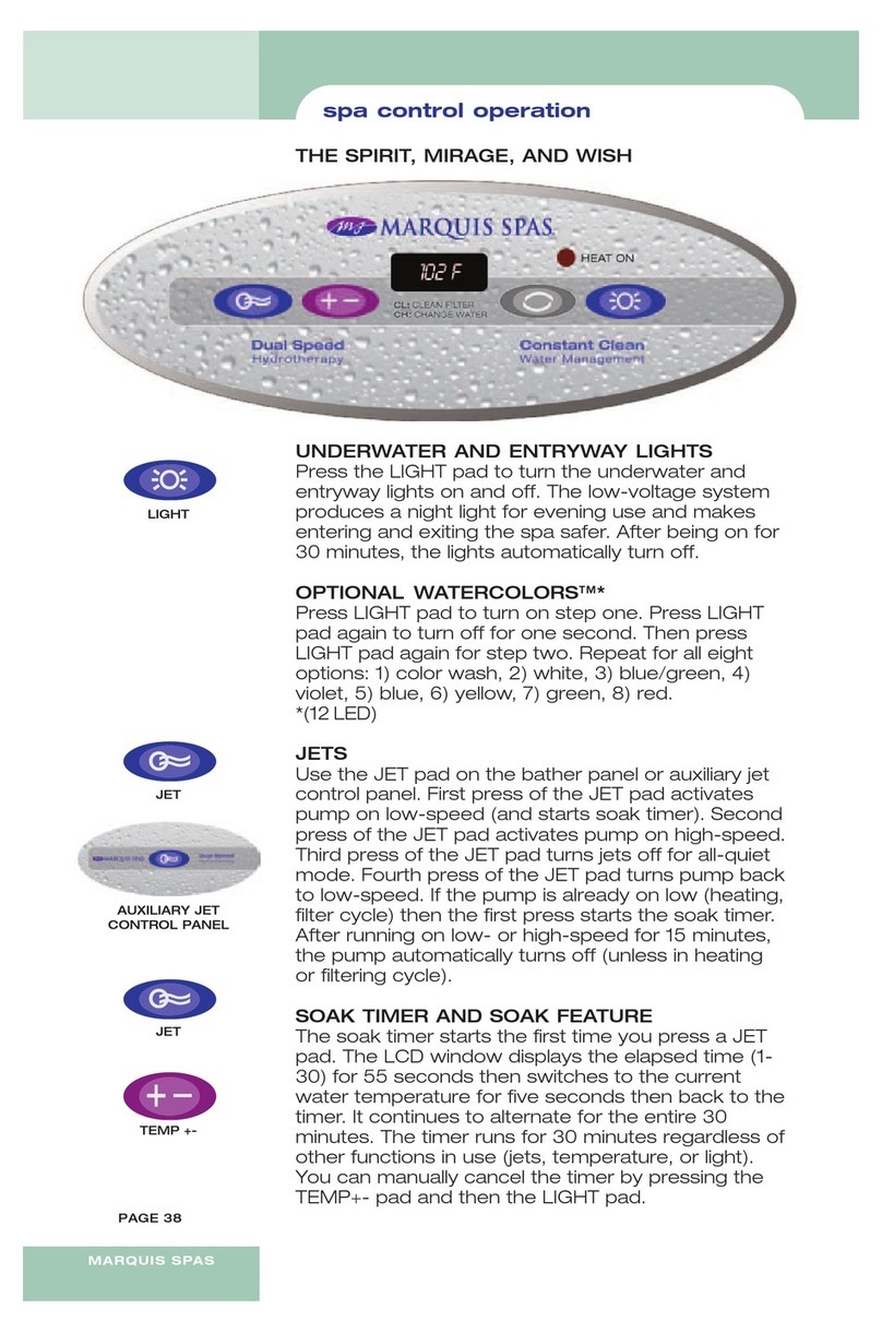
9-Button: Show
8-Button: Epic, Euphoria, Promise 2P, Resort, Reward, Wish
7-Button: Spirit, Mirage, Promise 1P, Rendezvous
PUMP PRIMING (Pr)
Pump priming feature begins at start-up. When your spa is energized, the LCD
window displays a “Pr” message. This mode lasts approximately four to five
minutes, if not exited manually by pressing the TEMP+ pad.
Your hot tub has been configured at the factory to run without any additional
programming changes other than setting the desired temperature. We do
however recommend that the time is set as this will be shown in the display as a
convenience and aids in controlling when the hot tub will filter. See “changing
the system settings” below on setting the time.
The hot tub controls are state of the art and will retain all of the settings or
changes that have been made in the event of a power failure.
CONTROL PANEL OPERATION INSTRUCTIONS
HOT KEYS
Using pump 1:
Pressing the Jets 1 button will turn pump 1 on low speed. Pressing a second
time will turn the pump on high speed. Pressing the button a third time will turn
the pump off. The pump will run for 15 minutes before shutting off or switching to
low speed. If the pump continues to run on low speed after the 15 minute
timeout, the system is either calling for heat or has entered into a filtration cycle.
Using pump 2 (if equipped):
Pressing the Jets/1 button will turn pump 1 on low speed. Pressing a second
time will turn the pump on high speed. Pressing the button a third time will turn
the pump off. The pump will run for 15 minutes before shutting off or switching to
low speed.
Using pump 3 (if equipped):
Pressing the Jets/1 button will turn pump 1 on low speed. Pressing a second
time will turn the pump on high speed. Pressing the button a third time will turn
the pump off. The pump will run for 15 minutes before shutting off or switching to
low speed.
Light:
Pressing the light button will turn the LED lights on. Pressing a second time will
turn them off. If left on the LED lights will automatically turn off after 30 minutes.
Special light feature: You can change the color of the LED lights by pressing the
light button repeatedly within 3 second intervals. Doing this will allow you to
scroll and choose a specific color or light sequence.
ALL QUIET SOAK FEATURE
Pressing the soak button activates a special feature that turns off all pumps and
heater, allowing for a quite soak in the hot water. Pressing the button a second
time will restore the unit back to normal operation. If left on, the soak mode will
time out after 15 minutes and revert back to normal operation.
Note: Periodically the pump/s may continue to operate for a short time after
pressing the soak button. This typically happens when the spa is in a heat cycle
as the heater will need a short period to cool down before stopping the water
flow.
SETTING THE TEMPERATURE
Pressing the temp up or temp down buttons allow you to adjust the heat to the
desired temperature. The set temperature is shown in the left hand side of the
LCD display. Pressing and holding the temp up or temp down button will allow
for an accelerated change of the temp.
Factory default temperature: 38°C
Maximum set temperature: 40°C
Minimum set temperature: 16°C
CHANGING THE SYSTEM SETTINGS
A few basic keystrokes will allow for easy navigation of the available
programming options. The settings, soak, temp up and temp down buttons also
serve as side to side and up and down navigation controls when in the menu.
Note the arrows on the buttons. The back/set button in the center is used to
save a setting or go back one screen at a time.
Tip! Note that the menu item that is selected will be brighter in the display than
the others indicating where you are in the menu.
Tip! If you have accidentally entered the setting menu, simply press the back/set
button or wait 30 seconds to go back to the home screen.
Programming choices shown in the main and sub menus. (See definitions of
menu and sub menu items.)
Heat Mode (main menu item)
Ready
Rest
Time of day (main menu item)
Current set time
Filter cycles (main menu item)
Filter cycle 1 and filter cycle 2
Preferences (main menu item)
Temp display –Choose between Fahrenheit “F” or Celsius “F”
Time display –choose between 12 or 24 hour display
Cleanup –choose the length of time of the clean-up cycle
Language –choose between English, Spanish, French or German
Diagnostics (main menu item
Spa
Information
A/B Temps
Fault Log
To make a change, perform the following sequence
1. Press the setting button to display the main settings menu
2. Press the settings button to move over into the main settings
menu
3. Scroll down by pressing the temp down button to the desired
menu item
4. Press the settings button to move into the sub menu
5. Press the temp up or temp down to change the parameters
(Note if a change is made, the save and cancel icons appear
on the left hand side of the screen)
6. Press the soak button to move to the left to the save icon.
Note the save icon will be brighter than everything else.

8
7. Press the back/set button to save you selection. If you want
to cancel your choice us the temp down button to navigate to
the cancel icon or simply wait 30 seconds which will end the
programming session.
Definitions of menu and sub menu items
Heat mode –Ready or Rest options
The Ready mode will have the spa at the set temperature at all
times.
The Rest mode will only heat during a filtration cycle. This is useful
if you are going to be gone for an extended amount of time and
want to conserve on power required to keep the spa hot at all times
Time of day
Setting the time of day will establish the current time in the main display screen
of the panel. It is also important for controlling when filtration cycles will run.
Filter Cycles:
Filter cycle 1 is set at the factory to run for 1 hour.
Filter cycle 2 is set at the factory to run for 1 hour.
Adjusting the time of the filtration cycle/s is a matter of personal
preference and usage patterns. Setting the filtration cycles for late
at night can avoid higher electrical rate costs as an example. If you
live in a climate that is seasonally hot, running the filtration cycle at
night can avoid unwanted heat build-up from the pumps and
prolong the life of the equipment. If your usage patterns are heavy
and you would like additional filtration to occur, you have the choice
of extending the filtration time or changing the second cycle to a
different part of the day.
Preferences
Temp display: Factory set to Fahrenheit “F” but can be changed to
Celsius “C” in alignment with local methods of displaying
temperature
Time display: Factory set to 12 hour but can be changed to 24 hour.
12 hour will display “AM” and “PM” after the time if 12 hour is
chosen. Choosing 24 hour will display the time in military time.
Clean-up: Factory set to 30 minutes (.5hr). A clean-up cycle will
start 30 minutes after you have finished using the hot tub. You
have the ability to extend the clean-up time in .5 hour increments to
suit your usage patterns and increase the filtration of the water after
use.
Language: Factory set to English. Choose between English,
Spanish, French and German to support your specific language in
the display.
Diagnostics
Spa, Information, A/B Temps and Fault Log are sub menu items
used for troubleshooting issues you may encounter with the hot tub
operation. These functions can only be viewed and not changed.
Typically these functions will be used by a service technician but
can be helpful to the owner when reporting an issue to the dealer or
service technician over the phone.
Auxiliary jet buttons: (if equipped)
Depending on the model of hot tub, there are may be up to two auxiliary jet
controls for operating the jet pumps. Pressing the Jets button will turn pump on
low speed. Pressing a second time will turn the pump on high speed. Pressing
the button a third time will turn the pump off. The pump will run for 15 minutes
before shutting off or switching to low speed.
Wi-Fi control: (if equipped)
Your hot tub is configured with a special component that will allow wireless
control with most Apple based products such the iPod Touch, iPad and iPhone.
This is an exciting feature that allows wireless operation of the spa functions and
most settings.
Please note that the typical operating range is within 30 feet of the hot tub
depending on obstructions or location/orientation. The signal may not be strong
enough in some cases to adequately establish and hold communication
between the hot tub and your device especially when operating from indoors
and the signal has to travel through walls. Keep this in mind when placing your
hot tub during installation in an effort to keep any obstructions to a minimum.
Initial set up:
1. In order to communicate and operate the hot tub, you will need to
go to the App Store and download the free “Marquis Spas & Hot
Tubs” app to your device.
2. Go to the settings section on your Apple device and choose the “Wi-
Fi” tab. Be sure that the Wi-Fi selection slider is set to the “On”
position so your device will discover all available Wi-Fi choices.
Choose the tab labeled BWG followed by a series of numbers. Be
sure your device connects which should be shown by the presence
of a check mark next to the name.
3. Return to the main screen and open the Marquis App and proceed
to “connect” with the hot tub. Stopping the connection process and
restarting may be required. There is nothing wrong with the unit as
this can be caused by protocols issued by Apple Inc.
4. Once connected you will be able to operate the jets and light on the
control tab of the App. Moving to the settings tab will allow changing
the time, temperature and filtration settings of the hot tub.
Note: If your device goes to sleep, screen darkens, or is turned off you will need
to reconnect again with the hot tub in order to reestablish control.
Aquavision Monitor (option on Show)
Aquavison is a completely independent waterproof video monitor that is built to
the latest regulations in waterproofing and safety, it is designed to integrate into
your spa environment. Aquavision incorporates the latest state of the art screens
with the latest and best features. Aquavision features heated screen areas to
prevent the front from misting up in humid conditions or even freezing up in cold
conditions. The E-Suite™ features an Aquavision unit with Adagio™ audio
system and a wireless remote control.
Operating the Monitor
Gently push the PRESS pad on top of the self-rising monitor unit to raise it. To
lower the monitor unit gently push the PRESS pad. Make sure monitor unit is in
the down position before closing the spa cover. Monitor lift mechanism is
manufacturer-warranted against failure to lift due to manufacturing defects only.
Closing the spa cover with monitor in the up position or forcing the monitor down
too rapidly can result in damage. Please refer to the Aquavision manufacturer’s
owner’s manual for features, operation, and troubleshooting.
USE AND CARE OF AROMA INFUSIONS LIQUID FRAGRANCE
DISPENSING SYSTEM (SELECT MODELS ONLY)
Filling
Turn the top cap of the Aroma Infusions counterclockwise. Remove
the pump mechanism to expose the reservoir.
The reservoir will hold up to 8oz. of liquid aroma. Monitor the level
during filling to avoid overfilling. Hold the liquid level approximately
1” below the top during filling to ensure the proper operating level.
Once filled, replace the pump mechanism into the reservoir and turn
the cap clockwise. DO NOT over tighten.

9
Use
To dispense aroma into the water, press the small dispensing
button in the middle of the cap. When used for the first time, it will
take approximately 7 to 8 depressions of the button to fill the line
leading to the aroma discharge fitting in the spa. Once filled, each
depression of the button will dispense aroma into the water.
Simply press the dispensing button to reach the desired level of
fragrance. The amount of fragrance you desire will be dependent on
the number of times you press the button.
Be aware that it will take a few moments for the fragrance to mix
with the water and become apparent above the water level of the
spa. Typically two to three depressions of the button will be
satisfactory.
The top button can be locked to avoid accidental use. To lock,
simply turn the button clockwise ¼ turn. To unlock, turn
counterclockwise ¼ turn.
Care
We recommend periodic cleaning of the reservoir and pump
mechanism. This is easily done by using removing the top cap and
filling with fresh warm water from the tap. After filling, reinstall the
cap and press the dispensing button 65 to 75 times. This will empty
all of the water from the reservoir and have it ready for refilling with
liquid fragrance.
When switching fragrances you may want to perform the cleaning
function to remove any residual of the previous fragrance.
The fragrance contains oils that over time may form and collect in
the filter cartridges. Routine and periodic cleaning of the filter
cartridges is recommended to maintain optimum filtration of the hot
tub water. Heavy use or large quantities of dispensed fragrance will
accelerate the need for cleaning the filter cartridges.
ADAGIO™ AUDIO SYSTEMS
Adagio™ Stereo
Adagio is easy to operate with logical push pad controls and function keys.
Please refer to the Infinity owner’s manual for features, operation, and
troubleshooting.
Adagio™ Pop Up Speakers
(If equipped) gently push the top of the self-rising speakers to raise them. To
lower the speakers gently push the speaker top until it is completely closed.
Make sure speakers are in the down position before closing the spa cover.
Speaker lift mechanism is manufacturer-warranted against failure to lift due to
manufacturing defects only. Closing the spa cover with speakers in the up
position or forcing the speaker down too rapidly can result in damage.
• CAUTION - Risk of Electric Shock. Replace components only with identical
components.
• Do not operate the audio controls while inside the spa.
• WARNING –Prevent Electrocution. Do not connect any auxiliary
components (for example, cable, additional speakers, headphones,
additional audio/video components, etc.) to the system, except as provided
by the following: The 3.5 mm auxiliary jack and USB are designed for input
only from devices such as an MP3 player operating at 4.5 V or less.
• These units are not provided with an outdoor antennae; it should be installed
in accordance with Article 810 of the National Electrical Code, ANSI/NFPA
70.
• Do not service this product yourself as opening or removing covers may
expose you to dangerous voltage or other risk of injury. Refer all servicing to
qualified service personnel.
• If the power supply connections or power supply cord(s) are damaged; if
water is entering the audio compartment or any electrical equipment
compartment area; if the protective shields or barriers are showing signs of
deterioration; or if there are signs of other potential damage to the unit, turn
off the unit and refer servicing to a qualified service personnel.
• This unit should be subjected to periodic routine maintenance (for example,
once every three months) to make sure that the unit is operating properly.
Adagio™ Audio Expansion Port (optional)
The built-in audio expansion port allows you to connect optional accessories. Use of a
MP3 player or USB memory stick are supported. NOTE: The 3.5 cm auxiliary jack is
designed for input only from devices such as an MP3 player operating at 4.5V or less.

10
EQUIPMENT DIAGRAMS
MIRAGE & RENDEZVOUS EQUIPMENT DIAGRAM
SPIRIT EQUIPMENT DIAGRAM
# Component Qty
1 Control Box and Heater 1
2 Ozonator 1
3 Pump 1
4 Pump Unions 2
5/7 Slice Valves 2
6 Check Valve 1
8 Drain Valve 1
9 GFCI 1
10 Light 1
11 Stereo Power Supply (option) 1
12 Adagio™ Stereo Head (option) 1
13 MP3 Auxiliary Jack (option) 1
14 Wi-Fi Transceiver (option) 1
PROMISE 1P EQUIPMENT DIAGRAM
# Component Qty
1 Control Box and Heater 1
2 Light 1
3 Pump 1
4 Pump Unions 2
5 Ozonator 1
6 Check Valve 1
7 Slice Valves 2
8 Drain Valve 1
9 Stereo Power Supply (option) 1
10 Adagio™ Stereo Head (option) 1
11 MP3 Auxiliary Jack (option) 1
12 Constellation (option) 1
13 Wi-Fi Transceiver (option) 1
PROMISE 2P, EPIC, EUPHORIA, WISH EQUIPMENT DIAGRAM
# Component Qty
1 Control Box and Heater 1
2 Pump 1
3 Pump 1
4 Pump Unions 4
5 Ozonator 1
6 Check Valve 1
7 Slice Valves 2
8 Drain Valve 1
9 Stereo Power Supply (option) 1
10 Adagio™ Stereo Head (option) 1
11 MP3 Auxiliary Jack (option) 1
12 Constellation (option) 1
13 Wi-Fi Transceiver (option) 1
14 Light 1

11
REWARD EQUIPMENT DIAGRAM
RESORT EQUIPMENT DIAGRAM
# Component Qty
1 Control Box and Heater 1
2 Pump Unions 4
3/4 Pumps 2
5 Ozonator 1
6 Check Valve 1
7 Slice Valves 2
8 Drain Valve 1
9 Stereo Power Supply (option) 1
10 Adagio™ Stereo Head (option) 1
11 MP3 Auxiliary Jack (option) 1
12 Constellation™ LED Control (option) 1
13 Wi-Fi Transceiver (option) 1
15 Light 1
SHOW EQUIPMENT DIAGRAM
# Component Qty
1 Control Box and Heater 1
3 Pumps* 2
4 Pump Unions 4
5 Ozonator 1
6 Check Valve 1
7 Slice Valves 2
8 Drain Valve 1
9 Stereo Power Supply (option) 1
11 Adagio™ Stereo Head (option) 1
12 MP3 Auxiliary Jack (option) 1
13 Constellation™ LED Control (option) 1
14 Wi-Fi Transceiver (option) 1
*Auxiliary pumps are located in the corners

12
EPIC™
# Component Identification Quantity
0 HK™8 Neck Jets 4
1 HK™8 Jets 12
2 HK™12 Jets 20
3 HK™16 Jets 17
4 HK™40 Jets 10
5 Geyser Jets 2
6 Light* 1
7 Air Controls 2
8 Suction Fittings 3
9 Floor Drain 1
10 Tri-Zone Control 2
11 Neck Jet Valves 2
12 Bather’s Control Panel 1
13 Filter Canisters 2
14 Spa Frog®* 1
15 Spa Frog® Return Fitting* 1
16 Ozone Injector Fitting* 1
17 Waterfall Feature* 2
18 Waterfall Valve* 1
19 Adagio™ Speakers 2
20 Cushioned Headrests* 3
21 Water Features* 2
EUPHORIA™
# Component Identification Quantity
0 HK™8 Neck Jets 4
1 HK™8 Jets 18
2 HK™12 Jets 8
3 HK™16 Jets 17
4 HK™40 Jets 13
5 Light* 1
6 Suction Fittings 3
7 Floor Drain 1
8 Jet Selector 2
9 Neck Jet Valve 2
10 Air Controls 2
11 Bather’s Control Panel 1
12 Auxiliary Control 2
13 Spa Frog®* 1
14 Filter Canisters 2
15 Waterfall Valve* 1
16 Adagio™ Speakers 2
17 Cushioned Headrests* 4
18 Water Features* 2
Epic Tri-Zone Control
ZONE 1 (JETS A)
Upper-, mid- and lower-back jets
ZONE 1 (JETS B)
Upper-, mid-, lower-back and foot jets
ZONE 1 (JETS B)
HOT Zone lumbar lounge
ZONE 2 (JETS B)
HOT Zone shoulder
ZONE 1 (JETS C)
Lounge, leg and foot jets
ZONE 2 (JETS C)
Geyser jets
HK™8 jets operate in every zone.
Euphoria Tri-Zone Control
ZONE 1 (JETS 1)
Mid- and lower-back jets
ZONE 1 (JETS2)
Upper-back jets
ZONE 1 (JETS 3)
Whirlpool jets
Physical Specifications Size
Dimensions/mm 229 x 229
Height/mm 89
Corner Radius/mm 305
Seating Positions 7
Weight Dry/Kgs. 386
Weight Full/Kgs. 2088
Water Capacity/Litres 1703
Total Therapy Jets 65
Physical Specifications Size
Dimensions/mm 229 x 229
Height/mm 89
Corner Radius/mm 305
Seating Capacity/Positions 7
Weight Dry/Kgs. 374
Weight Full/Kgs. 1887
Water Capacity/Litres 1514
Total Therapy Jets 58

13
MIRAGE™
# Component Identification Quantity
0 HK™8 Neck Jets 2
1 HK™8 Jets 19
2 HK™12 Jets 5
3 HK™16 Jets 12
5 Light* 1
6 Suction Fittings 2
7 Floor Drain 1
8 Jet Selector 1
9 Neck Jet Valve 1
10 Air Control 1
11 Bather’s Control Panel 1
12 Spa Frog®* 1
13 Spa Frog® Return Fitting* 1
14 Filter Canister 1
15 Ozone Injector Fitting* 1
16 Waterfall Feature* 1
20 Cushioned Headrests* 3
21 Adagio™ Speakers 4
22 Water Feature* 2
Mirage Zone Control
ZONE 1A
Upper-back jets.**
ZONE 1B
Mid- and lower-back jets.**
ZONE 1C
Leg and foot jets.**
*Items are optional. Check with dealer for
availability.
**HK™8 Neck Jets operate in every zone.
Physical Specifications Size
Dimensions/mm 207 x 207
Height/mm 89
Corner Radius/mm 305
Seating Capacity/Positions 4/5
Weight Dry/Kgs. 204
Weight Full/Kgs. 1207
Water Capacity/Litres 1003
Total Therapy Jets 38
Euphoria Tri-Zone Control
ZONE 2 (JETS 1)
Leg, wrist, upper- and mid-back jets.*
ZONE 2 (JETS2)
Leg, upper-, mid- and lower-back jets.**
ZONE 2 (JETS 3)
Whirlpool jets.**

14
PROMISE™
# Component Identification Quantity
0 HK™8 Neck Jets 2
1 HK™8 Jets 21
2 HK™12 Jets 15
3 HK™16 Jets 8
5 Light* 1
7 Suction Fittings 2
8 Floor Drain 1
9 Air Control 2
10 Neck Jet Valve 1
11 Bather’s Control Panel 1
12 Filter Canister 1
13 Spa Frog®* 1
14 Spa Frog® Return Fitting* 1
15 Ozone Injector Fitting* 1
20 Cushioned Headrests* 2
21 Adagio™ Speakers 4
22 Water Feature* 1
23 Aroma Infusions* 1
24 Aroma Infusions injector* 1
Promise Tri-Zone Control
ZONE 1A
ZONE 1B
RENDEZVOUS™
# Component Identification Quantity
1 HK™8 Neck Jets 2
2 HK™12 Jets 4
3 HK™16 Jets 8
5 Light* 1
7 Suction Fittings 2
8 Floor Drain 1
9 Air Control 1
10 Neck Jet Valve 1
11 Bather’s Control Panel 1
12 Filter Canister 1
13 Spa Frog®* 1
14 Spa Frog® Return Fitting* 1
15 Ozone Injector Fitting* 1
20 Cushioned Headrests* 2
21 Adagio™ Speakers 4
22 Water Feature* 1
Physical Specifications Size
Dimensions/mm 190 x 190
Height/mm 75
Corner Radius/mm 305
Seating Positions 3
Weight Dry/Kgs. 188
Weight Full/Kgs. 643
Water Capacity/Litres 644
Total Therapy Jets 14
Physical Specifications Size
Dimensions/mm 200 x 217
Height/mm 89
Corner Radius/mm 305
Seating Positions 6/7
Weight Dry/Kgs. 268
Weight Full/Kgs. 1516
Water Capacity/Litres 1454
Total Therapy Jets 46
ZONE 2A
ZONE 2B
*Items are optional. Check with dealer for
availability.
**HK™8 Neck Jets operate in every zone.
.

15
RESORT™
# Component Identification Quantity
0 HK™8 Neck Jets 2
1 HK™8 Jets 11
2 HK™12 Jets 21
3 HK™16 Jets 12
4 HK™40 Jets 10
5 Geyser Jets 2
5 Light* 1
7 Suction Fittings 4
8 Floor Drain 1
9 Jet Selector 1
10 Neck Jet Valve 1
11 Bather’s Control Panel 1
12 Filter Canisters 2
13 Spa Frog®* 1
14 Spa Frog® Return Fitting* 1
15 Ozone Injector Fitting* 1
17 Waterfall Valve 1
18 Adagio™ Speakers 2
19 Cushioned Headrests 3
20 Water Features 2
Resort Zone Control
ZONE 1 A
ZONE 1 B
ZONE 1C
REWARD™
# Component Identification Quantity
0 HK™8 Neck Jets 2
1 HK™8 Jets 5
2 HK™12 Jets 31
3 HK™16 Jets 12
4 HK™40 Jets 10
5 Light* 1
7 Suction Fittings 3
8 Floor Drain 1
9 Jet Selector 1
10 Neck Jet Valve 1
11 Bather’s Control Panel 1
12 Filter Canisters 2
13 Spa Frog®* 1
14 Spa Frog® Return Fitting* 1
15 Ozone Injector Fitting* 1
17 Waterfall Valve 1
18 Adagio™ Speakers 2
20 Cushioned Headrests 3
22 Water Features 2
Reward Zone Control
ZONE 1
ZONE 2
*Items are optional. Check with dealer for
availability.
**HK™8 Neck Jets operate in every zone.
Physical Specifications Size
Dimensions/mm 217 x 217
Height/mm 89
Corner Radius/mm 305
Seating Capacity/Positions 6
Weight Dry/Kgs. 336
Weight Full/Kgs. 1660
Water Capacity/Litres 1325
Total Therapy Jets 58
Physical Specifications Size
Dimensions/mm 217 x 217
Height/mm 89
Corner Radius/mm 305
Seating Capacity/Positions 5
Weight Dry/Kgs. 345
Water Capacity/Litres 1325
Total Therapy Jets 60
ZONE 2 A
ZONE 2 B
ZONE 2 C

16
SHOW™
# Component Identification Quantity
0 HK™8 Neck Jets 6
1 HK™8 Jets 18
2 HK™12 Jets 25
3 HK™16 Jets 7
4 HK™40 Jets 26
5 Light* 1
6 Air Controls 3
7 Suction Fittings 4
8 Floor Drain 1
9 Jet Selectors 3
10 Neck Jet Valves 3
11 Bather’s Control Panel 1
12 Filter Canisters 2
13 Spa Frog®* 1
14 Spa Frog® Return Fitting* 1
15 Ozone Injector Fitting* 1
17 Waterfall Valve* 1
18 Adagio™ Speakers* 2
19 Constellation* 16
20 Cushioned Headrests* 4
22 Water Features* 2
23 Cooler 1
24 TV* 1
25 Pump Interior Locations 2
Show Tri-Zone Control
ZONE 4 (JETS 1)
Adiriondack A: upper-back..**
ZONE 5 (JETS 2)
Adiriondack B: lower-back.**
ZONE 6 (JETS 3)
Captain’s Chair: lower-back.**
ZONE 7 (JETS 1)
Adiriondack A: feet.**
ZONE 8 (JETS 2)
Adiriondack B: feet.**
ZONE 9 (JETS 3)
Therapy pillar: legs and feet.**
*Items are optional. Check with dealer for
availability.
**HK™8 Neck Jets operate in every zone
Physical Specifications Size
Dimensions/mm 229 x 239
Height/mm 89
Corner Radius/mm 432
Seating Positions 5
Weight Dry/Kgs. 499
Weight Full/Kgs. 2296
Water Capacity/Litres 1798
Total Therapy Jets 82
Show Tri-Zone Control
ZONE 1 (JETS 1)
Adirondack A: all back, hips, legs and feet.**
ZONE 2 (JETS 2)
Adirondack B: upper- and mid-back, hips and
feet.**
ZONE 3 (JETS 3)
Captain’s Chair: mid- and lower-back, arms, knees
and wrists.**
Seat: all back.**

17
SPIRIT™
# Component Identification Quantity
0 HK 8™ Neck Jets 2
1 HK™8 Jets 3
2 HK™12 Jets 8
3 HK™16 Jets 15
4 HK™40 Jets 4
5 Light* 1
7 Suction Fitting 1
8 Floor Drain 1
9 Jet Selector 1
10 Neck Jet Valve 1
11 Bather’s Control Panel 1
12 Filter Canisters 1
13 Spa Frog®* 1
14 Spa Frog® Return Fitting* 1
15 Ozone Injector Fitting* 1
16 Waterfall Feature* 1
17 Waterfall Valve* 1
20 Cushioned Headrests* 2
21 Adagio™ Speakers* 2
22 Water Feature* 1
WISH™
# Component Identification Quantity
0 HK™8 Neck Jets 2
1 HK™8 Jets 24
2 HK™12 Jets 10
3 HK™16 Jets 4
4 HK™40 Jets 9
5 Geyser Jet 1
6 Light* 1
7 Air Controls 2
8 Suction Fittings 3
9 Floor Drain 1
10 Jet Selectors 2
11 Neck Jet Valve 1
12 Bather’s Control Panel 1
13 Auxiliary Control (Jets/Light) 1
14 Filter Canisters 2
15 Spa Frog®* 1
16 Spa Frog® Return Fitting* 1
17 Ozone Injector Fitting* 1
18 Waterfall Valve* 1
19 Adagio™ Speakers* 2
20 Constellation*
21 Cushioned Headrests* 3
22 Waterfall Feature* 1
Physical Specifications Size
Dimensions/mm 213 x 168
Height/mm 89
Corner Radius/mm 305
Seating Capacity/Positions 3/4
Weight Dry/Kgs. 209
Weight Full/Kgs. 965
Water Capacity/Litres 757
Total Therapy Jets 32
Physical Specifications Size
Dimensions/mm 213 x 213
Height/mm 89
Corner Radius/mm 305
Seating Capacity/Positions 3/4
Weight Dry/Kgs. 356
Weight Full/Kgs. 1642
Water Capacity/Litres 1287
Total Therapy Jets 50
Wish Tri-Zone Control
ZONE 1 (JETS 1)
Lounge leg and foot jets.**
ZONE 1 (JETS 2)
Upper-, mid-, and lower-back jets.**
ZONE 7 (JETS 1)
Spirit Tri-Zone Control
ZONE 1 (JETS 1)
Upper- and mid-back jets
ZONE 1 (JETS 2)
Lower- body and leg lounge jets
ZONE 1 (JETS 3)
Whirlpool jets

18
Wish Tri-Zone Control
ZONE 1 (JETS 3)
Lounge upper-back jets**
ZONE 2 (JETS1)
Upper- and mid-back jets.**
ZONE 2 (JETS2)
Lower-back and Geyser jets**

19
TROUBLESHOOTING GUIDE
PLEASE NOTE: The following corrective actions may be performed by the spa
owner. If the trouble cannot be corrected in the steps below, please contact your
authorized Marquis®dealer for service. (Improper servicing by an unauthorized
service provider or spa owner could result in damage not covered by the
warranty and could cause serious injury.)
EQUIPMENT WILL NOT OPERATE
Check the control panel LCD window for diagnostic code.
Check the circuit breaker on the main circuit panel.
Check the condition of the power cord.
INADEQUATE JET ACTION
Be sure the shut-off valves in the equipment area are completely open.
Open the jets by turning the jet face to allow for maximum water flow.
Check that the air control valve is open (rotate lever counterclockwise).
Check for obstruction or restrictions at suction guard(s) or filters, such
as leaves, etc.
JET VALVES ARE HARD TO OPERATE
Valves and rotating jets that become hard to turn is an indication of
sand, dirt or too high calcium level in the water.
Remove components and rinse before damage occurs.
Advise bathers to shower or use a foot bath before entering the spa.
Failure to use or maintain valves as directed may cause damage by
introduction of foreign materials such as dirt, sand and calcium that is
not covered under the warranty.
NO HEAT
•Check temperature displayed in the LCD window for desired
temperature setting.
•Inspect the filter cartridge(s) for dirt and debris.
•Check that the water is at proper level, 2/3 up the Vortex skimmer
opening(s).
•Check HEAT MODE to be certain spa is not in REST MODE.
•Lower ambient temperatures may result in heat loss.
NOTE: Do not expect instant hot water from the jets. It will take the heater 12-24
hours to heat the water to the temperature you desire.
GENERAL MESSAGES
Most messages and alerts will appear at the bottom of the normally used
screens. Several alerts and messages may be displayed in a sequence.
Some messages can be reset from the panel. Messages that can be reset will
appear with a “right arrow” at the end of the message. This message can be
selected by navigating to it at pressing the Select button.
---ºF ---ºC
WATER TEMPERATURE IS UNKNOWN
•After the pump has been running for 1 minute, the temperature will be
displayed.
POSSIBLE FREEZING CONDITION
•A potential freeze condition has been detected, or the Aux Freeze
Switch has closed. All water devices are activated. In some cases,
pumps may turn on and off and the heater may operate during Freeze
Protection. This is an operational message, not an error indication.
THE WATER IS TOO HOT - M029
•The system has detected a spa water temp of 43.3ºC or more, and the
spa functions are disabled. System will auto reset when the spa water
temp is below 42.2ºC. Check for extended pump operation or high
ambient temp.
HEATER-RELATED MESSAGES
THE WATER FLOW IS LOW - M016
•There may not be enough water flow through the heater to carry the heat
away from the heating element. Heater startup will begin again after about
1 minute. See “Flow Related Checks” below.
THE WATER FLOW HAS FAILED* - M017
•There is not enough water flow through the heater to carry the heat away
from the heating element and the heater has been disabled. See “Flow
Related Checks” below. After the problem has been resolved, you must
press any button to reset and begin heater start up.
THE HEATER MAY BE DRY* - M028
•Possible dry heater, or not enough water in the heater to start it. The spa
is shut down for 15 min. Press any button to reset the heater start up. See
“Flow Related Checks” below.
THE HEATER IS TOO HOT* - M30
•One of the water temp sensors has detected 118ºF (47.8ºC) in the heater
and the spa is shut down. You must clear the message when water is
below 108ºF (42.2ºC). See “Flow Related Checks” below.
FLOW-RELATED CHECKS
•Check for low water level, suction flow restrictions, closed valves, trapped
air, too many closed jets and pump prime.
•On some systems, even when spa is shut down by an error condition,
some equipment may occasionally turn on to continue monitoring
temperature or if freeze protection is needed.
*This message can be reset from the topside panel.
SENSOR-RELATED MESSAGES
SENSORS ARE OUT OF SYNC - M015
•The temperature sensors MAY be out of sync by -17ºC or -16ºC. Call for
service.
SENSORS ARE OUT OF SYNC -- CALL FOR SERVICE* - M026
•The temperature sensors ARE out of sync. The fault above has been
established for at least 1 hour. Call for service.
SENSOR A FAULT, SENOR B FAULT - SENSOR A: M031, SENSOR B: M032
•A temperature sensor or sensor circuit has failed. Call for service.
MISCELLANEOUS MESSAGES
COMMUNICATIONS ERROR
•The control panel is not receiving communication from the System. Call
for service.
TEST SOFTWARE INSTALLED
•The Control System is operating with test software. Call for service.
ºF or ºC is replaced by ºT
The Control System is in Test Mode. Call for service.

20
SYSTEM-RELATED MESSAGES
PROGRAM MEMORY FAILURE* - M022
•At Power-up, the system has failed the Program Checksum Test. This
indicates a problem with the firmware (operation program) and requires
a service call.
THE SETTINGS HAVE BEEN RESET (PERSISTENT MEMORY ERROR)* -
M021
•Contact your dealer or service organization if this message appears on
more than one power-up.
THE CLOCK HAS FAILED* - M020
•Contact your dealer or service organization.
CONFIGURATION ERROR (SPA WILL NOT START UP)
•Contact your dealer or service organization.
A PUMP MAY BE STUCK ON - M034
•Water may be overheated. POWER DOWN THE SPA. DO NOT
ENTER THE WATER. Contact your dealer or service organization.
HOT FAULT - M035
•A pump appears to be stuck ON when spa was last powered. POWER
DOWN SPA IMMEDIATELY. DO NOT ENTER THE WATER. Contact
dealer or service organization.
*This message can be reset from the topside panel.
MAINTENANCE
WEEKLY MAINTENANCE
1. Removing Debris
Remove any debris and leaves from the Vortex skimmers and suction
guard(s) on the inside of the spa. Blocked intakes can impede the flow of
water through the jetting system.
2. Water Level
Replenish the water level if necessary so that it is approximately two-thirds
up the Vortex skimmer opening. (See STARTING YOUR SPA.) Low and
high water levels can damage your spa. It is important to check your water
level often.
MONTHLY MAINTENANCE
1. Filter Care
We cannot stress enough the importance of a clean filter for proper water
filtration. Dirty filters can restrict water flow, cause hazy water, and prevent
your chemicals from working properly. Dirty filters can also cause low flow
from jets, poor water clarity and sensors to activate error codes. It is
important to clean filters regularly. Many water treatment products clear or
clarify the water by clumping microscopic particles and minerals together so
that these larger particles can be effectively trapped in the filter. A filter
clogged with debris and calcium deposits does not trap particles properly.
The Maintenance Reminder on the spa-side Control Panel indicates a CL
every 30 days to remind you to clean your filter.
EVERY THREE TO FOUR MONTHS
Leakage Detection
Open the equipment door and check for signs of water leakage around the
pump(s). Pump seals wear out over time, especially with improper water
chemistry. Early detection of pump seal failure can significantly reduce repair costs.
Ozonator Operation
The ozonator functions whenever the system is running on filter or clean up
cycles. Check to see if the bulb is lighted. The end cap of the ozonator should
glow if functioning properly. If not, the bulb has burned out. Contact your dealer
for service.
Draining and Filling the Spa
On average, a spa needs to be drained every three to four months. After months
of continually adding chemicals to the water and introducing body oils and
lotions, the water can be difficult to manage and chemicals are not as effective
as usual. You may also notice excessive foaming. More frequent draining may be
required depending on use.
Draining the Spa
A. Turn off the power to the spa.
B. Open the equipment compartment (see EQUIPMENT DIAGRAM).
Remove the hose bib cap from the connection and attach a hose.
C. Openthe drain valve. Gravity causes the water to drain out of the hose.
D. When the spa is empty, close the drain valve and remove the hose.
Reinstall the hose bib plug.
NOTE: Keep the drain valve closed at all times except when draining the
spa (do not rely on the cap to stop the flow of water). Not doing so could
result in damage to the drain valve due to freezing water.
AS NEEDED MAINTENANCE
Cover Care
Proper care of the cover increases the life and keeps it looking great in even the
harshest conditions. NOTE: Do not use regular household products or products
that contain silicone, alcohol, steel wool, or bleach.
Synthetic Exterior Care
Clean the exterior of the spa with a mild soap and water solution. Cleaners that
contain alcohol or high levels of solvents, along with Acetone, Nitrobenzene, and
Cyclohexanol, can dissolve and discolor the synthetic exterior.
Clean the Acrylic Interior
Once the spa is drained, clean the acrylic interior thoroughly: especially at the
water line. Bleach (diluted) is the recommended cleaning agent for acrylic –
other products should be avoided except as stated below.
To maintain the high gloss, elegant look of LUCITE XL just follow these simple
steps: Use common household, non-abrasive cleaners for most cleaning jobs.
For normal care and cleaning use a soft cloth or sponge with soap and water.
Rinse well and dry with a soft, clean cloth. If using a household cleaner, make
sure it is recommended for use on acrylic by the manufacturer. Never use
abrasive cleaners. Do not allow your acrylic surface to come into contact with
products such as ketones or esters such as acetone or ethyl acetate (nail polish
remover), Wintergreen oil (methyl salicylate), nail polish, dry cleaning solution or
other chlorinated organic solvents, lacquer thinners, gasoline, aromatic solvents,
pine oil, etc. Remove dust and dry dirt with a soft, damp cloth. Clean grease, oil,
paint and ink stains with isopropyl (rubbing) alcohol. Dry with a clean, soft cloth.
Avoid using razor blades or other sharp instruments that might scratch the
surface.
NOTE: Due to the high-gloss, fine finish of the acrylics, imperfections in the
surface texture may occur. A natural aging process in acrylic can lead to a
process called crazing. Fine spider web-like lines can form on the cosmetic
surface of acrylic over time after exposure to the elements and chemicals.
Crazing represents no structural weakening of acrylic and is not covered under
the warranty. Fading, staining and discoloration may also occur but represent no
structural degradation and are not covered under warranty.
NOTE: Do not leave an empty spa uncovered. Direct sunlight on the spa surface
can cause severe damage or blemishing and can result in the voiding of any
surface warranties.
Excess Debris
Grit and debris tracked into the spa should be removed with a spa vacuum.
This manual suits for next models
9
Table of contents
Other Marquis Hot Tub manuals

Marquis
Marquis E-series User manual

Marquis
Marquis Everyday Hot Tub User manual

Marquis
Marquis Spas User manual

Marquis
Marquis 660 User manual

Marquis
Marquis Vector21 Series User manual

Marquis
Marquis ATV-14 User manual

Marquis
Marquis 660 User manual

Marquis
Marquis ULTIMATE HOT TUB EXPERIENCE! User manual

Marquis
Marquis e-serie User manual

Marquis
Marquis Spas User manual