Mars Comfort-Aire Century WHDEHUM-90P User manual

www.marsdelivers.com
Installation and Operation Manual
WHDEHUM-90P
Whole House Dehumidier

Installation and Operation Manual - WHDEHUM-90P
2
READ AND SAVE THESE INSTRUCTIONS
TABLE OF CONTENTS
Introduction....................................................................................................................................... 2
Contents ......................................................................................................................................... 3
Specications ................................................................................................................................... 3
Operating Modes/Congurations...................................................................................................... 4
Unit Location..................................................................................................................................... 4
Installation ........................................................................................................................................ 5
Wiring................................................................................................................................................7
Unit Controls..................................................................................................................................... 8
Conguration & Operation................................................................................................................9
Maintenance................................................................................................................................... 10
Warranty...........................................................................................................................................11
PLEASE COMPLETE THE FOLLOWING ON DAY OF
INSTALLATION. HOMEOWNER TO RETAIN FOR FUTURE
INFORMATIONAL PURPOSES.
Unit Model Number ______________________________________________________________
Serial Number __________________________________________________________________
Installation Date _________________________________________________________________
Installing Contractor Name ________________________________________________________
Installing Contractor Phone ________________________________________________________
Introduction
CAUTION
Read the entire manual carefully and completely before installing this product. Installation and maintenance
should be completed by qualied personnel. Installation contrary to these guidelines may void warranty.
The benets of a properly humidied environment are many. They include personal comfort as well as
the preservation of furniture, draperies, carpets, wooden oors and cabinets, paintings, pianos, etc.
Higher humidity levels can also increase the growth-rate of mold, bacteria, viruses, and even dust mites
in the home. Your home can be more comfortable at a warmer temperature with drier air than without
controlling humidity during the humid summer months. Since every degree of temperature change
represents about 3% to 5% of the total cooling costs, each degree warmer you can set the thermostat
can represent a signicant annual savings.
During the cooling season, warm, moist air inltrates the home and must be cooled. When cooled, this air
can still be humid as air conditioners are designed to cool the air, not dehumidify the air. A small amount
of dehumidication may be a benet of air conditioners, but they actually work harder and longer to cool
the air when the air is moist. Only by using a whole house dehumidier to reduce the humidity in the entire
home’s air, can a balance between humidity levels, temperature, comfort, and energy costs be optimized.

Installation and Operation Manual - WHDEHUM-90P
3
The following items are included with your
Comfort-Aire/Century dehumidier:
• WHDEHUM-90P dehumidier
• 20’ standard AC cable
• 12” drain hose, which can be lengthened
(see below)
• Installation/operation manual
If any items are not found, please contact
Comfort-Aire/Century Customer Service at
877-442-4482.
The following are a list of items that may be
required for a complete installation:
• 6-inch round exible output air ducting
and clamping, if not operating in
standalone unit mode (length determined
by installation location)
• For the WHDEHUM-90P, a 12-inch
round exible input air ducting and
clamping, if not operating in standalone
unit mode (length determined by
installation location)
• Remote humidistat and possibly a
24VAC control voltage source, if not
operating in standalone unit mode
• Condensate pump (if not easy to reach
gravity-fed drain)
• Air duct take-offs and conversions as
necessary, if not operating in standalone
mode
• ½” ID plastic or vinyl drain hose long
enough to reach gravity-fed drain or
condensate pump; connects to a ½”
hose barb located at the bottom of
dehumidier
• 18-20 gauge thermostat wire for control
wiring
Contents Specifications
Specication WHDEHUM-90P
Capacity (@ 80°F, 60% RH) 90 Pints per Day
Operating Relative Humidity 35-95%
Operating Temperature Range 33°-105°F
Volts/Hertz 120VAC/60 Hz
Full Load Current (@ 80°F, 60% RH) 5.5 Amps
Coefcient of Performance 2.80 L/kWh
Energy Star Rated Yes
Refrigerant R410A
Airow @ 0.00” S.P. 370 CFM
Inlet Filter Washable Pre-Filter and
MERV 8 Cassette
Inlet Duct 12”
Outlet Duct 6”
Power Cord 20-ft Standard 3-Prong AC
Sound Level 58 dBa
Drain Pipe Connection 12-¾” OD, ½” ID Vinyl
Tubing
Digital Control for Standalone
Operation Yes
Dimensions L x W x H 23.4” x 13.7” x 17”
Weight 65 Pounds
ETL Listed Yes

Installation and Operation Manual - WHDEHUM-90P
4
Operating Modes/Configurations
The Comfort-Aire/Century WHDEHUM-90P
supports whole-house dehumidication and
standalone unit dehumidication modes for
crawlspace and basement applications.
Standalone Unit Dehumidication
Standalone Unit Dehumidication (SUD) is typically
used to dry basements and crawlspaces. For
this application, the WHDEHUM-90P is capable
of operating in a complete standalone mode in a
ductless conguration that does not require any
extra ducting or control system hook-ups. In SUD
mode, the unit has an integrated humidistat and
controller. The user just connects power, plumbs
in the water drain, turns the unit on, congures the
unit control for SUD mode, then sets the desired
humidity and leaves it alone. Thereafter, the unit
automatically senses the humidity level and turns
on as needed to remove access moisture in the air.
Whole-House Dehumidication
There are two whole-house dehumidication
congurations that can be addressed with
the WHDEHUM-90P. In the rst of these
congurations (see Figure 1, page 4), the
dehumidier serves the whole house but is not
duct-integrated with the HVAC system. Secondly,
the unit shares the return and supply ducting of
the HVAC system and may even share a common
integrated thermostat/humidistat (see Figure 2A
and 2B, page 4).
Separate Duct Systems
Whole-house separated dehumidication systems
have traditionally been utilized to support separate,
more isolated rooms that require dehumidication.
As of late, there is a growing trend towards mini-split
HVAC systems that are implemented as heating
and cooling systems. Separated dehumidication
congurations are ideal solutions for mini-split based
HVAC systems.
Separate duct systems operate independent of
the HVAC system and are located in basements,
crawlspaces, or perhaps in a closet with ducting to
and from the living area to be humidied.
HVAC Duct Systems
Whole-house HVAC duct systems are
dehumidication congurations in which
the WHDEHUM-90P will be directly duct-
interconnected with the home’s central HVAC
system and typically share control elements
to ensure that the units properly functions with
the ducted airow. Below are the likely system
example drawings of HVAC congurations.
The dehumidier can be installed in a variety of lo-
cations to meet the owner’s needs as listed below.
In all cases, keep the following cautions in mind:
1. The unit is designed to be installed indoors in
a space that is protected from rain, ooding,
and/or other forms of excess water. Unit is not
designed to be exposed to chlorinated pool
conditions or corrosive chemicals or conditions.
2. Install the unit with space to access the front
panel for maintenance and service. Also, allow
easy access to the lter cover panel.
3. Avoid discharging the air directly at people,
over the water in pool areas, or other areas or
objects where dehydration or evaporation of
moisture is not desired.
4. If used near wet areas, be certain there is NO
chance the unit could fall into the water or be
Figure 1. Whole-Home Separate Duct System
Figure 2B. Whole-Home HVAC Duct System
Figure 2A. Whole-Home HVAC Duct System
Unit Location

Installation and Operation Manual - WHDEHUM-90P
5
splashed and that it is wired into a GROUND
FAULT INTERRUPTER protected circuit.
5. A secondary drain pan MUST be placed under
the unit if installed above a living area or above
an area where water leakage could cause dam-
age (see local codes for other requirements)
6. DO NOT position the dehumidier directly on
structural members where noise or vibration
may be objectionable. The unit is equipped with
adjustable support feet to raise and level the
unit from the mounting surface; these adjust-
able feet should be utilized to provide improved
drainage from the drain pan and should be
adjusted to tilt slightly toward the drain utilized.
7. The unit should be located near the existing
air handling system to minimize the required
ductwork for connection of the dehumidier to
the existing HVAC air handling system. When
the option is used, the control (humidistat) unit
must be located in the space that is to be con-
ditioned. The control (humidistat) must be low
voltage (24V) and should be connected to the
unit with code approved, low voltage thermostat
cable.
8. When locating the dehumidier in areas of ex-
treme heat or high humidity, >120-degrees/90%
humidity, additional external insulation may be
required to prevent undesired condensation on
the exterior of the unit.
Common Installation Instructions Across All
Congurations
Step 1: Placement of the Dehumidier Unit
IMPORTANT: If the dehumidier unit is handled in
such a manner that the compressor did not remain
in the upright position, it is necessary to place on
a level surface and wait a minimum of two hours
before turning the unit on.
Additionally, the Comfort-Aire/Century dehumidier
cannot sit directly on the oor unless the unit
condensate drain output is feeding directly into a
sump pump next to it.
When placing, the dehumidier unit is equipped
with adjustable feet that can be used along with a
leveling tool to make sure the dehumidier rests in
a completely “level” nal state as needed for proper
operation.
Step 2: Set Up Drain Line
The condensate drain line should be routed to a
suitable drain to carry the condensate water to the
outside. The drain line must ow down without any
loops, dips, or valleys to the nal drain hole.
Recommended Dehumidier Drain Cong-
uration Including a Transition to PVC Pipe
1. Cut a piece of ¾” OD PVC that is 6” minimum.
2. Insert PVC into a ¾” elbow, then attach a ¾”
OD length of PVC to drain. Keep the length
of the PVC drain pipe to a minimum and make
sure it ows down.
3. Insert the open end of the dehumidier
condensate tubing into the ¾” pipe so that
it does not extend into the elbow tting. For
proper ow, a minimum downward slope of
1” per 10’ run is required. NOTE: If a proper
downward angle is not possible, then it is
recommended to use an external condensate
Installation
WARNING
Standalone Unit Dehumidication congu-
rations, as noted, are typically used to dry
basements and crawlspaces. To be properly
dehumidied, the area to be controlled should
be sealed with a vapor barrier. If the unit is to
be installed in a crawlspace, all vents to the
outdoors should be sealed. Do not install your
humidier in a corrosive environment. Some
liquid barriers dry via “solvent evaporation”.
Always ensure the barrier is completely dry and
area is thoroughly ventilated before installing
dehumidier.
Figure 3. Drain Tube Drawing

Installation and Operation Manual - WHDEHUM-90P
6
pump conguration. This will require expert
installation.
4. Support the PVC tubing so that it maintains a
smooth downward ow to drain.
5. Always test the drain before leaving the
installation area.
Step 3: Electrical Power Connections
The dehumidier is equipped with a 3-prong,
standard 120VAC electrical plug. Given operation
in damp and wet environments, and to put safety
rst, the required electrical outlet to be used to
connect the dehumidiers should have:
1. Ground Fault Circuit Interrupter (GFCI)
2. 15 Amp minimum circuit that cannot be shared
with any other signicant load
120VAC may cause serious injury from electric
shock. To ensure safety:
1. Disconnect electrical power before servicing.
2. Only plug unit into grounded electrical circuit.
3. Do not use extension cord.
4. Do not use a plug adapter.
Step 4: General Ducting Points and
Requirements
In all cases, sound duct design practices must be
followed, such as those provided in ACCA manual
“D” of ASHRAE’s Fundamentals of Air System
Design.
For supply side air ducting (output from the
dehumidier), the WHDEHUM-90P has a 6” round
duct.
For return side ducting, the dehumidier is
equipped as follows:
• A 12” round collar.
For ducting material to use between existing ducts
or new ducts with the dehumidier, it is advisable
to select an acoustical ex duct material on all
dehumidier duct connections to reduce noise
and vibration transmitted to rigid ductwork in the
structure. At the same time, ex ducting is very
easy to use and eliminates the need for very
detailed measurement, cutting, and duct forming.
Ducting for Standalone Unit Conguration
For Standalone Unit Dehumidication, there is not
a connection to existing HVAC ductwork. In the
SUD case, when installing the dehumidier inside a
sealed crawlspace, a basement, or a sealed attic,
the ducting requirements are recommended as
follows:
1. If the area is open without partitions and the
dehumidier can be located near the center
of the zone, then the return ducting is not
absolutely necessary. Still, a minimum length
of supply duct of just 3’ to 6’ will aid in overall
air distribution. The short supply duct distance
will support carrying the dehumidied air far
enough away from the unit that it will not be
quickly reprocessed again as returned air.
2. If the area being served is divided by walls or
partitions, then the return duct should be routed
to a second area/zone than the area where the
dehumidier is placed - and the supply duct
should be routed to even a third area. These
different areas will help push the air between
the walls and/or partitions.
3. A similar but reverse strategy as #1 above, if
the dehumidier needs to be located along the
perimeter in a more open zone, then a single
return to the dehumidier should be installed
in the central open area of the structure to aid
overall air distribution.
Ducting for Whole-House Separate Room
Figure 1 on page 4 depicts an example system
conguration that is in a residential living
environment but is not interconnected with an
existing HVAC system. The dehumidier unit
is separated given the living area is not in close
proximity with the HVAC system, or the existing
HVAC system could be a mini-split without any
ductwork to connect with. In either case, the
dehumidier is to be installed with its own separate
ducting, including both return and supply side.
Return Ducting for Whole-House Separate Room
The return duct length is not overly critical, and
it is acceptable to provide more than a single
WARNING
In all cases, local codes precede over
installation and wiring recommendations. Do
not plug the dehumidiers into the outlet until all
the control circuitry is properly connected.

Installation and Operation Manual - WHDEHUM-90P
7
return path to the dehumidier to improve overall
airow from other far apart rooms. CAUTION: Be
sure that grills and/or diffusers do not excessively
restrict airow.
Supply Ducting for Whole-House Separate Room
For the supply output ducting (output air from the
dehumidier), the total duct length should be less
than 10 feet total to reduce the back pressure on
the dehumidier blower. CAUTION: Be sure that
grills and/or diffusers do not excessively restrict
airow.
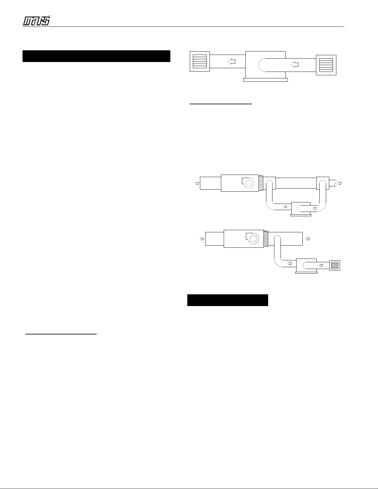
Ducting for Whole-House HVAC Conguration
For whole-house HVAC duct connections, please
reference Figures 2A and 2B on page 4. In both of
these congurations, the dehumidier is placed in
the return path of the HVAC system.
For Figure 2A, the dehumidier sources its return air
connection from the HVAC return connection, and
then the source air connection from the dehumidier
is fed back to the HVAC return air duct a few feet
downstream. For whole-house HVAC, this is the
most common, most effective, and easiest ducting
implementation to use. It is best because it is
dehumidifying the air ahead of the air conditioning
coil system to eliminate the wettest air rst ahead of
the HVAC coils. This enhances the overall cooling
system efciency. Also, by inputting air from the
HVAC return duct and returning the conditioned
air to the same HVAC return duct, there is not an
additional air pressure differential to overcome. In
this conguration, keep the length of the dehumidier
return and source ducting at a minimum.
For the second whole-house HVAC conguration,
please reference Figure 2B on page 4. The
difference from Figure 2A is that the dehumidier
return path is independent from the HVAC return
path. In this conguration, the dehumidier has its
own completely independent and dedicated ducting
and return air grill. This conguration is ideal when
there is a need to dry a specic conditioned or
unconditioned area. An example would be to feed
the separate room from the main living area, which
would maximize the airow from there, proving a
living area that likely is more dry than the other living
areas.
Discussed and illustrated here will be the basic
control scenario for three classes of dehumidier
control:
1. Standalone unit dehumidication
2. Whole-house separated dehumidication
3. Whole-house using high integration consolidated
thermostat and humidistat
SUD Congurations
No extra control wiring is required for SUD
congurations, as the dehumidier in this mode
operates completely standalone, sampling humidity
from the local air - and then using the settings made
by the user interface to either switch-on or switch-
off. Please reference the Operation section for
details on how to congure and use the dehumidier
in standalone congurations.
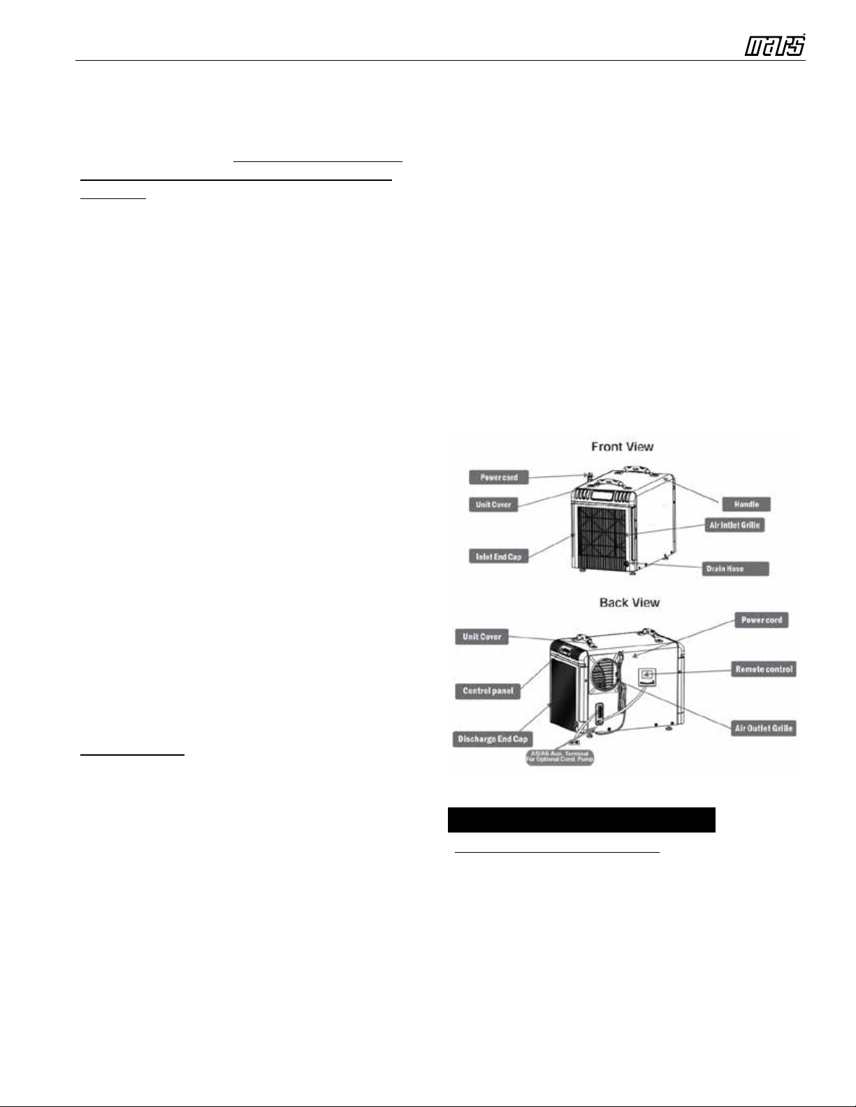
Whole-House Separated Room Congurations
This type can be controlled with the addition of a
single humidistat located in the living area that is
to be served by the dehumidier. See Figure 4 on
page 8 to guide specic hook-ups. For external
control, the dehumidiers are connected to the
control systems with the 6-position terminal strip as
illustrated.
Terminals A3 and A4 need to be powered to switch
the dehumidier on, typically connecting A4 to the
control voltage common signal (C) and switching
the 24VAC control hot signal (R) through a set of
normally open contacts typically integrated into
the separate humidistat. When the humidity rises
above the set-point, the humidistat contacts close,
which then connects the dehumidier pin A3 to
24VAC and switches the dehumidier ON.
To implement a required interlock with the HVAC
fan control, interconnect dehumidier terminal strip
connections A3 to A2 as illustrated below. Then,
connect the dehumidier terminal strip A1 back to
the HVAC “green” connection, which typically turns
the HVAC fan ON.
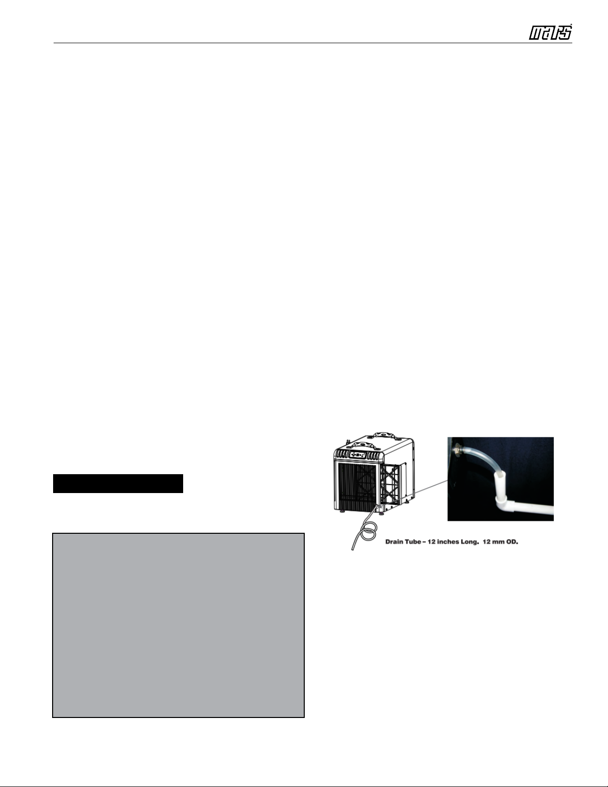
Also in the illustration below, please note the
functionality associated with dehumidier connections
A5 and A6. A5 and A6 can be used to interlock
the dehumidier to the condensate drain system.
Wiring

Installation and Operation Manual - WHDEHUM-90P
8
If the water does not properly drain and the oat
switch closes, this will cause an error function to be
triggered by the dehumidier, which will cause the
unit to permanently shut off. The error condition can
only be reset by switching the dehumidier breaker
off, then back on or by unplugging power from the
dehumidier.
Whole-House HVAC Congurations
An increasing number of systems are being
implemented with combination thermostat/
humidistats. In the same spirit of consolidated
control, there are also high integration thermostats
that include two different humidity control
capabilities. The rst provides separate control
for a humidier typically required during heating
season, and the second provides separate control
for a dehumidier during the air conditioning
season. At the same time, control systems have
also become multi-speed controllers as required
to interoperate with high efciency heat-pump and
forced air systems.
The Comfort-Aire/Century dehumidier is equipped
with the basic required interconnection as
illustrated in Figure 4 below. However, this manual
does not provide interconnection diagrams for
the multitude of integrated thermostat/humidistats
A1 A2 A3 A4 A5 A6
NORMALLY OPEN FLOAT SWITCH
(PERMANENTLY CLOSES TO DISABLE
DEHUMIDIFIER)
G
*If the dehumidier is installed in an attic or another location requiring
leak protection, the unit should be placed in a condensate pan with
a normally closed, condensate overow safety switch (oat switch).
Wire the oat switch to terminals A5 and A6 as shown.
R
C
DH
DH
HVAC SYSTEM
TERMINALS
EXTERNAL
DEHUMIDISTAT
TERMINALS
Wiring shows connection of external humidistat to dehumidier terminals.
Dehumidier will start HVAC blower upon a call for dehumidication. When
te call is satised, the dehumidier will act to turn o the HVAC blower
unless there is a call for cooling present. At that time, the HVAC
thermostat/air handler will be controlling the HVAC blower.
JUMPER
WIRE
DEHUMIDIFIER TERMINALS
Figure 4. Wiring Diagram
* If the dehumidier is installed in an attic or another location requiring leak protection, the unit should be placed in
a condensate pan with a normally open, condensate overow safety switch (oat switch). Wire the oat switch to
Terminals A5 and A6 as shown.
currently available. The installation and control
should be performed by an expert HVAC technician
who will have the required knowledge to properly
prescribe and interconnect a specic combination
thermostat/humidistat.
Operation of the dehumidier is supported with
both the unit control panel and optional humidistat
for whole-house congurations. In either case,
the dehumidier conguration is set using the
dehumidier control panel shown below.
Button Functions
1. Power Button ON/OFF
Use this button to turn the dehumidier ON and
OFF. Press once to turn the machine ON. You
will hear a beep, and the power light will illuminate
Unit Controls
Figure 5. Dehumidier Control Panel

Installation and Operation Manual - WHDEHUM-90P
9
red. If in Unit/Standalone mode, press the button
a second time, and you will hear one beep as the
machine shuts down. Specially note that there
is a one minute fan delay from button push to
shutdown. In addition, the dehumidier, once
congured for operation, will automatically return to
that mode during power glitch or outage.
If the dehumidier is switched ON and then put
into Remote/Whole-House Mode, the unit cannot
be turned off with the switch. If in the Remote/
Whole-House Mode and you want to turn the main
power off, then switch the dehumidier into Unit/
Standalone Mode that re-arms the OFF switch
(both mode indicator lamps off). Thereafter, the
power switch can be used to switch OFF.
2. Arrow Buttons ▲ Up and ▼ Down
Use the Up and Down arrow buttons to set the
humidity set point on the display screen, when
using in SUD conguration. The set points can be
any number between 35 to 99. Creating a set point
means that when the indoor humidity is lower than
the set point, the machine will stop automatically.
Conversely, when the indoor humidity is higher
than the set point, the button is pushed and the unit
will switch ON to run.
3. Central Control Conguration Button
Press this button to switch the dehumidier
between Standalone Unit Conguration and Whole-
House Conguration. Whole-House Conguration
is selected when the green lamp is turned on
above.
Indicator Lights
1. Humidity Display Screen
The display screen has two functions. When the
unit is powered ON, it shows the local humidity.
While setting the desired humidity level, the screen
will show the set point humidity level.
2. Power Indicator Light
This light indicates that the unit is properly powered
ON and ready to operate in Standalone Mode. In
Remote/Whole-House Mode, the Power Indicator
only illuminates when the unit is running. Always
make sure this unit is OFF prior to performing any
service.
3. Continuous Mode/Auto Defrost Light
When this light illuminates green, it indicates that
the dehumidier is set to Continuous Operation
Mode. When the light glows red, it means the unit
is in Auto Defrost Mode and clearing the evaporator
coil of any ice buildup.
4. Compressor Light
When the Compressor light glows red, it indicates
that the compressor has been initiated to run but is
currently warming up. Once the compressor light
switches to green, it indicates that the compressor
is in working status.
5. Whole-House Indicator Light
When the indicator light is green, it illustrates the
unit is congured for Whole-House Conguration
and not Standalone Mode. While in Whole-House
Conguration, the dehumidier is to be controlled
by a separate humidistat.
Standalone Unit Conguration
After the dehumidier is properly installed, ducted,
connected to AC power, and condensate drain
plumbed, standard operation can be congured
and initiated.
Step 1
Push the power switch to turn the dehumidier
ON. TEST MODE can be initiated by switching
the dehumidier into Standalone/Unit Mode then
by pressing and holding down both arrow buttons.
Configuration & Operation
Figure 6. WHDEHUM-90P

Installation and Operation Manual - WHDEHUM-90P
10
Press down both arrow buttons again to turn off
TEST MODE (continual on function).
Step 2
Press the Central Control button until the Whole-
House light turns OFF, which indicates the unit is
congured for Standalone/Unit Mode of operation.
Step 3
Next, see the Humidity Screen Display, which will
indicate the current local humidity. Use the Up/
Down arrow buttons to set the humidity set point for
the dehumidier. If the humidity rises above the set
point, then the dehumidier will switch ON and run
continuously until the humidity set point is achieved.
There may be a 1-2 minute delay when the unit starts
a dehumidier ON cycle before it actually begins
dehumidifying, as there is a compressor warm-up
cycle required and indicated by a red Compressor
light. Likewise, if powering OFF, there may be a short
one minute delay required for the unit to cycle down
and shut off.
Step 4
From there, the unit will run and only needs to be
switched OFF for cleaning and maintenance if
necessary.
Whole-House Conguration
After the dehumidier is properly installed, ducted,
humidistat control wired, connected to AC power,
and condensate drain plumbed, standard operation
can be congured and initiated.
Step 1
Be sure to turn OFF the Dehumidier Mode on the
external humidistat controller before switching on
the dehumidier. Also, if an external oat switch
is being used for the condensate drain circuitry, be
sure the condensate tank is empty or near empty
and the associated oat switch is open.
Step 2
Push the power switch to turn the dehumidier ON.
Step 3
Press the Central Control button until the Whole-
House light turns on, which indicates the unit is
congured for Whole House Mode of operation.
After a very brief delay, the dehumidier will switch
into the Whole-House Mode.
Step 4
After setting the unit for Whole-House Mode in Step
3 above and from this point forward, the dehumidier
is exclusively controlled by the dehumidistat. At this
time, the humidistat controller can be turned on and
the humidity setting adjusted accordingly. When
the humidistat signals the need for dehumidication,
there may be a 1-2 minute delay when the unit
starts a dehumidier ON cycle before it really begins
dehumidifying, as there is a compressor warm-up
cycle required and indicated by a red Compressor
light. Likewise, if powering OFF, there may be a short
one minute delay required for the unit to cycle down
and shut off.
From here on, the unit will run and only needs to be
switched off for cleaning and maintenance if necessary.
WHDEHUM-90P
Cleaning the Machine Body
Use a soft damp cloth to clean exterior of unit. Do
not use any soap or solvents.
Cleaning the Filter (See Figure 7)
1. Unplug the unit.
2. Rotate the air inlet grille counterclockwise to
remove.
3. Clean the lter mesh by vacuuming or washing
with warm water (no soap or solvents).
4. Reinsert the air inlet grille by rotating it
clockwise onto the unit.
5. Be sure lter is completely dry before restarting
unit.
Coil Maintenance
Once per year, clean the coils with an approved
coil cleaner. Coil cleaner should be a self-rinsing,
foaming cleaner such as WEB® Coil Cleaner.
Maintenance
2
34
Figure 7. WHDEHUM-90P Maintenance Diagram

Installation and Operation Manual - WHDEHUM-90P
11
Congratulations on purchasing your new HVAC equipment. It has
been designed for long life and reliable service, and is backed by one
of the strongest warranties in the industry. Your unit automatically
qualifies for the warranty coverage listed below, provided you keep
your proof of purchase (receipt) for the equipment and meet the
warranty conditions.
LIMITED TWO (2) YEAR PARTS EXPRESS WARRANTY
All parts of the WHDEHUM-90P dehumidifier are warranted to be free from
defects in workmanship and materials for normal use and maintenance for
two (2) years from the date of purchase by the original consumer for the
original installation. The Limited Express Warranty applies only when the
unit is installed per the Comfort-Aire/Century installation instructions and in
accordance with all local, state and national codes for normal residential use.
LIMITED FIVE (5) YEAR EXTENDED EXPRESS WARRANTY
The compressor only is warranted to be free from defects in workmanship
and materials for five (5) years from the date of purchase to the original
consumer for the original residential installation, when the unit is registered
within 60 days of purchase. Additionally, all parts are warranted to be
free from defects in workmanship and materials for an two (2) years from
the date of purchase by the original consumer for the original residential
installation, when the unit is registered within 60 days of purchase.
EXCEPTIONS
The Limited Express Warranty does not cover normal maintenance—
Comfort-Aire/Century recommends that regular inspection/maintenance be
performed according to the Owner’s Manual. Additionally, labor charges,
transportation charges for replacement parts, replacement of refrigerant or
filters, any other service calls/repairs are not covered by this Limited Express
Warranty. It also does not cover any portion or component of the system that
is not supplied by Comfort-Aire/Century, regardless of the cause of failure of
such portion or component.
CONDITIONS FOR WARRANTY COVERAGE
• Unit must be operated according to the Comfort-Aire/Century operating
instructions included with the unit and cannot have been subjected to
accident, alteration, improper repair, neglect or misuse, or an act of God
(such as a flood)
• Serial numbers and/or rating plate have not been altered or removed
• Proof of proper maintenance over the unit’s lifetime must be supplied
• Installation was done by a trained, licensed or otherwise qualified HVAC
dealer/contractor
• Performance has not been impaired by use of any product not authorized
by Comfort-Aire/Century, or by any adjustments or adaptations to
components
• Damage has not been a result of inadequate wiring or voltage conditions,
use during brown-out conditions, or circuit interruptions
• Air flow around any section of the unit has not been restricted
• Unit remains in the original residential installation
• Warranty is valid only to the original purchaser (non-transferrable)
• Unit was not purchased over the internet
DURATION OF WARRANTY & REGISTRATION
The warranty begins on the date of purchase by the original consumer. The
original consumer must register at www.marsdelivers.com within 60 days of
purchase. The original consumer must retain a receipted bill of sale as
proof of warranty period (part numbers, serial numbers, purchase and
installation dates).
REMEDY PROVIDED BY THE LIMITED EXPRESS WARRANTY
The sole remedy under the Limited Express Warranty is replacement of
the defective part. If replacement parts are required within the period of
this warranty, Comfort-Aire/Century replacement parts shall be used; any
warranty on the replacement part(s) shall not affect the applicable original
unit warranty. Access to the unit for service is the owner’s responsibility.
Labor to diagnose and replace the defective part is not covered by this
Limited Express Warranty.
LIMITATION OF LIABILITY
1. EXCLUSION OF ALL IMPLIED WARRANTIES AND LIMITATION.
There are no other express or implied warranties. Comfort-Aire/
Century makes no warranty of merchantability. We do not warrant
that the unit is suitable for any particular purpose or can be used
in buildings or rooms of any particular size or condition except as
specifically provided in this document. There are no other warranties,
express or implied, which extend beyond the description in this
document.
2. All warranties implied by law are limited in duration to the term of the
parts warranty. Your exclusive remedy is limited to the replacement
of defective parts. We will not be liable for any consequential or
incidental damages caused by any defect in this unit.
3. This warranty gives you specific legal rights; you may also have
other rights which vary from state to state. Some states do not allow
limitation on how long an implied warranty lasts or do not allow the
exclusion or limitation of incidental and/or consequential damages,
so the above limitations or exclusions may not apply to you.
4. No warranties are made for units sold outside the continental United
States and Canada. Your distributor or final seller may provide a
warranty on units sold outside these areas.
5. Comfort-Aire/Century will not be liable for damages if our performance
regarding warranty resolution is delayed by events beyond our control
including accident, alteration, abuse, war, government restrictions, strikes,
fire, flood, or other acts of God.
COMMERCIAL INSTALLATION LIMITED EXPRESS WARRANTY
When installed in a commercial application, all parts and compressors are
warranted to be free from defects in material and workmanship for ONE
YEAR from the date of purchase by the original consumer for the original
installation.
LIMITED EXPRESS WARRANTY - WHDEHUM-90P
WHDEHUM_WARRANTY_7/2017
Please visit www.marsdelivers.com to register your new product
KEEP THIS INFORMATION AS A RECORD OF YOUR PURCHASE
Date of Purchase Date Installation Completed
o Component of new HVAC system
Remember to retain your bill of sale as proof of warranty period and ownership.
Apply Serial Number and Model Number sticker here
(from product carton). if unavailable, write serial number and
model number below (can be found on unit rating plate).
Please follow the below steps to register your product.
• Please log onto our website www.marsdelivers.com
• Resources
• Product Registration
• Complete the requested information in ALL CAPS, especially
the Email address
• Press the “Continue” button at the bottom
• A copy of the registration will be sent to the Email address
you entered at the top of the page (for your records)

:HOOZRUWK$YH-DFNVRQ0,3KZZZKHDWFRQWUROOHUFRP
'XHWRRQJRLQJSURGXFWLPSURYHPHQWVVSHFLILFDWLRQVDQGGLPHQVLRQVDUH
VXEMHFWWRFKDQJHDQGFRUUHFWLRQZLWKRXWQRWLFHRULQFXUULQJREOLJDWLRQV'HWHUPLQLQJWKH
DSSOLFDWLRQDQGVXLWDELOLW\IRUXVHRIDQ\SURGXFWLVWKHUHVSRQVLELOLW\RIWKHLQVWDOOHU
$GGLWLRQDOO\WKHLQVWDOOHULVUHVSRQVLEOHIRUYHULI\LQJGLPHQVLRQDOGDWDRQWKHDFWXDOSURGXFW
SULRUWREHJLQQLQJDQ\LQVWDOODWLRQSUHSDUDWLRQV
,QFHQWLYHDQGUHEDWHSURJUDPVKDYHSUHFLVHUHTXLUHPHQWVDVWRSURGXFWSHUIRUPDQFH
DQGFHUWLILFDWLRQ$OOSURGXFWVPHHWDSSOLFDEOHUHJXODWLRQVLQHIIHFWRQGDWHRIPDQXIDFWXUH
KRZHYHUFHUWLILFDWLRQVDUHQRWQHFHVVDULO\JUDQWHGIRUWKHOLIHRIDSURGXFW
7KHUHIRUHLWLVWKHUHVSRQVLELOLW\RIWKHDSSOLFDQWWRGHWHUPLQHZKHWKHUDVSHFLILF
PRGHOTXDOLILHVIRUWKHVHLQFHQWLYHUHEDWHSURJUDPV
7/2017
ZZZPDUVGHOLYHUVFRP
1900 Wellworth Ave., Jackson, MI 49203 • Ph. 517-787-2100 • www.marsdelivers.com
Table of contents
Other Mars Dehumidifier manuals
Popular Dehumidifier manuals by other brands

REMKO
REMKO SLE 20 Operation,technology,spare parts

Mitsubishi Electric
Mitsubishi Electric MJ-E82CF-H instruction manual

DanVex
DanVex AD-400 Operation manual

Stadler Form
Stadler Form Albert operating instructions

EIPL
EIPL CS90E owner's manual

Quest Engineering
Quest Engineering DRY 115 Installation, operation and maintenance instructions