Mars Comfort-Aire Century VFH-MB Series User manual

www.marsdelivers.com
Installation & Operation Manual
VFH-MB Series
Inverter Multi Zone Ductless Mini-Split
B-VFH09MB-1A
B-VFH12MB-1A
B-VFH18MB-1
B-VFH24MB-1

BLA,CK

3

Installation & Operation Manual - VFH-MB 09/12/18/24 Series
4
Table of Contents
Part Ė: Technical Information.......................................................................5
1. Summary......................................................................................................................5
6SHFL¿FDWLRQV..........................................................................................................6
6SHFL¿FDWLRQ6KHHW............................................................................................................6
1RLVH&XUYH.......................................................................................................................8
3. Outline Dimension Diagram..........................................................................9
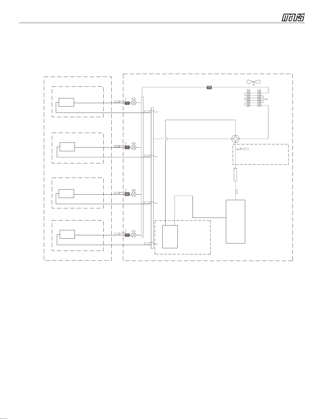
4. Refrigerant System Diagram.......................................................................10
5. Electrical Part............................................................................................................11
:LULQJ'LDJUDP.................................................................................................................11
3&%3ULQWHG'LDJUDP .......................................................................................................12
6.
Function and Control...........................................................................................13
5HPRWH&RQWUROOHU,QWURGXFWLRQ .......................................................................................13
%ULHI'HVFULSWLRQRI0RGHVDQG)XQFWLRQV........................................................................18
Part ė: Installation and Maintenance ....................................................22
7. Notes for Installation and Maintenance...............................................22
8. Installation...................................................................................................................24
,QVWDOODWLRQ'LPHQVLRQ'LDJUDP........................................................................................24
,QVWDOODWLRQ3DUWVFKHFNLQJ ..............................................................................................26
6HOHFWLRQRI,QVWDOODWLRQ/RFDWLRQ......................................................................................26
(OHFWULF&RQQHFWLRQ5HTXLUHPHQW.....................................................................................26
,QVWDOODWLRQRI,QGRRU8QLW..................................................................................................26
&KHFNDIWHU,QVWDOODWLRQDQG7HVWRSHUDWLRQ ......................................................................29
9. Maintenance...............................................................................................................30
(UURU&RGH........................................................................................................................30
3URFHGXUHRI7URXEOHVKRRWLQJ ..........................................................................................32
10.
Exploded View and Parts List
...................................................................37
11.
Removal Procedure............................................................................................45
Appendix:...........................................................................................................................52
$SSHQGL[5HIHUHQFH6KHHWRI&HOVLXVDQG)DKUHQKHLW .......................................................52
$SSHQGL[&RQ¿JXUDWLRQRI&RQQHFWLRQ3LSH........................................................................52
$SSHQGL[3LSHH[SDQGLQJPHWKRG.......................................................................................53
$SSHQGL[/LVWRI5HVLVWDQFHIRU7HPSHUDWXUH6HQVRU ..........................................................54

Installation & Operation Manual - VFH-MB 09/12/18/24 Series
5
1. Summary
Indoor Unit:
Part I: Technical Information
Remote Controller:
%9)+0%
%9)+0%
%9)+0%
%9)+0%
30510138_L61437
FAN
MODE
ON/OFF

Installation & Operation Manual - VFH-MB 09/12/18/24 Series
6
6SHFL¿FDWLRQV
6SHFL¿FDWLRQ6KHHW
7KHDERYHGDWDLVVXEMHFWWRFKDQJHZLWKRXWQRWLFHSOHDVHUHIHUWRWKHQDPHSODWHRIWKHXQLW
0RGHO %9)+0% %9)+0%
3URGXFW&RGH &%1B/ &%1B/
5DWHG9ROWDJH 9 208/230 208/230
5DWHG)UHTXHQF\ +] 60 60
3KDVHV
11
&RROLQJ&DSDFLW\ %WXK 9000 12000
+HDWLQJ&DSDFLW\ %WXK 9800 13000
$LUÀRZYROXPH6++0+00//6/ &)0 430/394/359/312/271/241/224 430/394/359/312/271/241/224
'HKXPLGLI\LQJ9ROXPH /K 0.8 1.4
)DQ7\SH &URVVÀRZ &URVVÀRZ
)DQ'LDPHWHUKHLJKW LQFK ĭ; ĭ;
)DQ0RWRU6SHHG&RROLQJ6++0+00//6/ USP 1400/1050/1000/900/800/700/550 1450/1070/1000/900/800/700/550
)DQ0RWRU6SHHG+HDWLQJ6++0+00//6/ USP 1400/1150/1080/1030/980/900/850 1400/1150/1080/1030/980/900/850
)DQ0RWRU3RZHU2XWSXW W10 10
)DQPRWRUUXQQLQJFXUUHQW A 0.07 0.07
)DQ0RWRU&DSDFLWRU ȝ)
//
(YDSRUDWRU0DWHULDO $OXPLQXP)LQFRSSHU7XEH $OXPLQXP)LQFRSSHU7XEH
(YDSRUDWRU3LSH'LDPHWHU LQFK ĭ ĭ
(YDSRUDWRU1XPEHURI5RZV)LQ3LWFK LQFK
&RLO/HQJWK/;';: LQFK ;; ;;
)XVH&XUUHQW A 3.15 3.15
6RXQG3UHVVXUH/HYHO6++0+00//6/ G%$ 42/36/34/32/28/24/21 43/36/34/32/28/24/22
6RXQG3RZHU/HYHO6++0+00//6/ G%$ 52/46/44/42/38/34/31 53/46/44/42/38/34/32
'LPHQVLRQRI2XWOLQH:;+;' LQFK ;; ;;
'LPHQVLRQRI&DUWRQ%R[/;:;+ LQFK ;; ;;
'LPHQVLRQRI3DFNDJH/;:;+ LQFK ;; ;;
1HW:HLJKW ,E 24.25 24.25
*URVV:HLJKW ,E 28.66 28.66
/LTXLGSLSH LQFK ĭ ĭ
*DV3LSHWRLQGRRUXQLW LQFK ĭ ĭ
1RWH7KHFRQQHFWLRQSLSHDSSOLHVPHWULFGLDPHWHU

Installation & Operation Manual - VFH-MB 09/12/18/24 Series
7
7KHDERYHGDWDLVVXEMHFWWRFKDQJHZLWKRXWQRWLFHSOHDVHUHIHUWRWKHQDPHSODWHRIWKHXQLW
0RGHO %9)+0% %9)+0%
3URGXFW&RGH &%1B/ &%1B/
5DWHG9ROWDJH 9~ 208/230 208/230
5DWHG)UHTXHQF\ +] 60 60
3KDVHV
11
&RROLQJ&DSDFLW\ %WXK a a
+HDWLQJ&DSDFLW\ %WXK a a
$LUÀRZYROXPH6++0+00//6/ &)0 559/512/465/418/371/330/282 647/589/530/471/412/353/294
'HKXPLGLI\LQJ9ROXPH 3LQWK 3.80 5.28
)DQ7\SH &URVVÀRZ &URVVÀRZ
'LDPHWHU/HQJWK';/ LQFK ĭ; ĭ;
)DQ0RWRU&RROLQJ6SHHG6++0+0
0//6/ UPLQ 1400/1300/1200/1100/1000/900/800 1400/1300/1200/1100/1000/900/800
)DQ0RWRU+HDWLQJ6SHHG6++0+0
0//6/ UPLQ 1450/1350/1250/1150/1050/950/850 1350/1350/1250/1150/1050/900/800
2XWSXWRI)DQ0RWRU W25 70
)DQ0RWRU5/$ A 0.10 0.38
)DQ0RWRU&DSDFLWRU ȝ)
//
(YDSRUDWRU)RUP $OXPLQXP)LQFRSSHU7XEH $OXPLQXP)LQFRSSHU7XEH
3LSH'LDPHWHU LQFK ĭ ĭ
5RZ¿Q*DS LQFK
&RLO/HQJWK/;';: LQFK ;; ;;
)XVH A 3.15 3.15
6RXQG3UHVVXUH/HYHO6++0+00/
/6/ G%$ 51/47/44/41/38/36/33 52/49/47/45/43/41/38
6RXQG3RZHU/HYHO6++0+00//
6/ G%$ 61/57/54/51/48/46/43 62/59/57/55/53/51/48
'LPHQVLRQ:;+;' LQFK ;; ;;
'LPHQVLRQRI&DUWRQ%R[/;:;+ LQFK ;; ;;
'LPHQVLRQRI3DFNDJH/;:;+ LQFK ;; ;;
1HW:HLJKW ,E 30.9 38.6
*URVV:HLJKW ,E 38.6 47.4
/LTXLG3LSH LQFK ĭ ĭ
*DV3LSHWRLQGRRUXQLW LQFK ĭ ĭ
1RWH7KHFRQQHFWLRQSLSHDSSOLHVPHWULFGLDPHWHU

Installation & Operation Manual - VFH-MB 09/12/18/24 Series
8
2.2 Noise Curve
0
10
Noice/dB(A)
20
30
40
50
60
Low Middle Super HighHigh
Indoor Fan Motor Rotating Speed
12K
09K
24K
18K
20
30
40
50
SL L ML MHM H SH
Indoor fan motor rating speed
Noise/dB(A)
B-VFH18MB-1/B-VFH24MB-1
B-VFH09MB-1/B-VFH12MB-1

Installation & Operation Manual - VFH-MB 09/12/18/24 Series
9
3. Outline Dimension Diagram
6 3/8
6 2/7
2/5
3 1/7
1 3/8
21 2/7 6 3/7
Φ2 1/6 Φ2 1/6
5 2/3 27 7 4/9
Φ2 3/4
Φ2 3/4 Φ2 3/4
Φ1/2
1 3/4
2 1/6
2 1/6
4 2/3
5 1/8 4
2
Φ2 3/4
7 29 3/8 10
'
+
W
0RGHO W+'
%9)+0%%9)+0% 34 11 1/2 8 7/32
%9)+0% 40 12 5/9 9
%9)+0% 46 3/8 12 5/6 10 2/5
%9)+0%%9)+0%
%9)+0%
%9)+0%
8QLWLQFK

Installation & Operation Manual - VFH-MB 09/12/18/24 Series
10
4. Refrigerant System Diagram
Outdoor
Indoor
D1
C1
B1
A1
filter
A heat exchanger
gas -liquid separator
inverter compressor
discharge silencer
discharge temperature
sensor
SP
4-way valve
outdoor heat exchanger
fan
high pressure switch
B heat exchanger
C heat exchanger
D heat exchanger
filter
filter
filter
filter
Note: Not available for 14K/18K
model
C2
C3
D3
D2
B3
B2
A2
A3
A1:A-unit electronic expansion valve B1:B-unit electronic expansion valve
C1:C-unit electronic expansion valve D1:D-unit electronic expansion valve
A2:A-unit gas pipe temperature sensor B2:B-unit gas pipe temperature sensor
C2:C-unit gas pipe temperature sensor D2:D-unit gas pipe temperature sensor
A3:A-unit liquid pipe temperature sensor B3:B-unit liquid pipe temperature sensor
C3:C-unit liquid pipe temperature sensor D3:D-unit liquid pipe temperature sensor
Note: Not available for 14K/18K model

Installation & Operation Manual - VFH-MB 09/12/18/24 Series
11
5. Electrical Part
5.1 Wiring Diagram
Ɣ,QVWUXFWLRQ
6\PERO 6\PERO&RORU 6\PERO 6\PERO&RORU 6\PERO 1DPH
:+ :KLWH GN *UHHQ &$3 -XPSHUFDS
YE <HOORZ %1 %URZQ &203 &RPSUHVVRU
5' 5HG %8 %OXH *URXQGLQJZLUH
YEGN <HOORZ*UHHQ %. %ODFN //
97 9LROHW 2* 2UDQJH //
1RWH-XPSHUFDSLVXVHGWRGHWHUPLQHIDQVSHHGDQGWKHVZLQJDQJOHRIKRUL]RQWDOORYHUIRUWKLVPRGHO
7KHVHZLULQJGLDJUDPVDUHVXEMHFWWRFKDQJHZLWKRXWQRWLFHSOHDVHUHIHUWRWKHRQHVXSSOLHGZLWKWKHXQLW
63632168
AP1
0
0
M2
SWING-LR
CAP
JUMP
PRINTED CIRCUIT BOARD
ROOM
RT1 RT2
TUBE
SENSOR SENSOR
ROOM TUBE
DC-MOTOR
FAN MOTOR
STEPPING
RECEIVER
DISPLAY
DISP2DISP1
TEMP. TEMP.
BOARD
AND
SWING-UD1 SWING-UD2
LEFT-RIGHT UP-DOWN
MOTOR STEPPING MOTOR STEPPING MOTOR
UP-DOWN
M3 M4
AP2
OUTDOOR UNIT
BLOCK
CABLE
TERMINAL
N(1)
2
3
XT
COM-OUT
AC-L
N
PE
BU
BK
BN
YEGN
ELECTRIC BOX
G
G
EVAPORATOR
YEGN
YEGN
AP3
MANUAL PANEL
CONNECTOR
COM-INNER1
(optional)
3
2
N(1)
M1

Installation & Operation Manual - VFH-MB 09/12/18/24 Series
12
5.2 PCB Printed Diagram
ƔTop view
ƔBottom view
1 Neutral wire
2 DC fan
3 Auto button
4 Small up&down swing
5 Left&right swing
6 Big up&down swing
7 Interface of wired controller
8 Display interface
9 Ambient temperature sensor
10 Tube temperature sensor
11 Communication interface between
indoor unit and outdoor unit
12 Interface of live wire
13 Fuse
14 Jumper interface
1 234 5
6
7
8
019
11312114

Installation & Operation Manual - VFH-MB 09/12/18/24 Series
13
6. Function and Control
6.1 Remote Controller Introduction
1
2
3
4
5
6
7
8
9
10
11
12
button
button
X-FAN button
QUIET button
SLEEP button
TEMP button
I FEEL button
13
14
15
16
TURBO button
LIGHT button
button
TIMER ON/
TIMER OFF button
CLOCK button
1
2
3
4
ON/OFF button
FAN button
+/- button
MODE button
ON/OFF button
FAN button
+/- button
MODE button
3
4
2
1
(before opening cover
/
1
15
5
2
6
3
12
16
4
11
8
9
13
7
(after opening cover
10
14
Buttons on Remote Controller
Introduction for Icons on Display Screen
Send signal
Turbo mode
8ć(46 ) heating function
Set temperature
Set time
X-FAN function
TIMER ON /TIMER OFF
Child lock
Up & down swing
Left & right swing
Set fan speed
Light
Temp. display type
: Set temp.
: Outdoor ambient temp.
: Indoor ambient temp.
Sleep mode
Clock
Heat mode
Fan mode
Dry mode
Cool mode
Auto mode
Operation mode
I feel
Healthy mode
Scavenging functions
Quiet
Ɖ
This is a general remote controller. S
o
models have this function while some
not. Please refer to the actual models.
Introduction for Buttons on Remote Controller
Note:
•7KLVLVDJHQHUDOXVHUHPRWHFRQWUROOHULWisXVHGIRUDLUFRQGLWLRQHUV ZLWKPXOWLIXQFWLRQ)RUVRPHIXQFWLRQsZKLFKWKHPRGHO
GRHVQWKDYHLISUHVVing WKHFRUUHVSRQGLQJEXWWRQRQWKHUHPRWHFRQWUROOHU,WKHXQLWZLOONHHSWKH RULJLQDOUXQQLQJVWDWXV
•$IWHUapplyingSRZHUWKHDLUFRQGLWLRQHUZLOOemitDVRXQG When operation indicator " " is ON (red indicator), you can operate the air
conditioner by using remote controller.
•8QGHURQVWDWXVSUHVVLQJWKHEXWWRQRQWKHUHPRWHFRQWUROOHUWKHVLJQDOLFRQRQWKHGLVSOD\RIUHPRWHFRQWUROOHUZLOOEOLQN once
DQG the air conditioner will emit a sound, which means the signal has been sent to the air conditioner.
•8QGHURIIVWDWXVVHWWHPSHUDWXUHDQGFORFNLFRQZLOOEHGLVSOD\HGRQWKHGLVSOD\RIUHPRWHFRQWUROOHU,IWLPHURQWLPHURIIDQG light
function are set, the corresponding icons will be displayed on the display of remote controller at the same time); Under on status, the
display will show the corresponding set function icons.
1. ON/OFF button
3UHVVWKLVEXWWRQ andWKHXQLWZLOOWXUQRQ;SUHVVLWRQFHPRUH andWKHXQLWZLOOWXUQRII6OHHSIXQFWLRQZLOOEHFDQFHOHGZKenXQLW isRII

Installation & Operation Manual - VFH-MB 09/12/18/24 Series
14
2. FAN button
3UHVVWKLVEXWWRQ$XWR/RZ0HGLXPORZ0HGLXP0HGLXPKLJK+LJKVSHHGFDQEHFLUFXODUO\VHOHFWHG$IWHUSRZHUHGRQ$XWRIDQVSHHG
LVGHIDXOW8QGHU'5<PRGH/RZIDQVSHHGRQO\FDQEHVHWXS
3. MODE button
3UHVVWKLVEXWWRQ$XWR&RRO'U\)DQ+HDWPRGHFDQEHVHOHFWHGFLUFXODUO\$XWRPRGHLVGHIDXOWZKLOHSRZHUedRQ8QGHU$XWRPRGH
the WHPSHUDWXUHZLOOQRWEHGLVSOD\HG Under Heat mode, the initial value is 28& ) 8QGHURWKHUPRGHVWKHLQLWLDOYDOXHLV&
)
+/- button
•3UHVHWWLQJWHPSHUDWXUHFDQEHLQFUHDVHG
3UHVVWKLVEXWWRQ WKHWHPSHUDWXUHFDQEHVHWXSFRQWLQXRXVO\SUHVVWKLVEXWWRQDQGKROGIRUWZRVHFRQGVWKHUHODWLYHFRQWHQWVwill
TXLFNO\FKDQJH XQWLOreleasingWKLVEXWWRQ 7KHWHPSHUDWXUHDGMXVWPHQWLVunavailable under Auto mode.
•3UHVHWWLQJWHPSHUDWXUHFDQEHGHFUHDVHG
3UHVVWKLVEXWWRQWKHWHPSHUDWXUHFDQEHVHWXSFRQWLQXRXVO\SUHVVWKLVEXWWRQDQGKROGIRUWZRVHFRQGVWKHUHODWLYHFRQWHQWVwill qui
ckly change. 7KHWHPSHUDWXUHDGMXVWPHQWLVXQDYDLODEOHinWKH$XWRPRGH
•TURBO button
8QGHU&RRORU+HDWPRGHSUHVVWKLVEXWWRQFDQWXUQRQRUWXUQRIIWKH7XUERIXQFWLRQ$IWHUWKH7XUERIXQFWLRQWXUQHGRQWKHVLJQDORI7 X
UER ZLOOGLVSOD\7KHVLJQDOZLOOEHDXWRPDWLFDOO\FDQFHOOHGLIFKDQJLQJWKHPRGHRUIDQVSHHG
•button
3UHVVWKLVEXWWRQWRVHWOHIWULJKWVZLQJDQJOHF\FOLQJDVEHORZ
7. button
3UHVVWKLVEXWWRQwillVHWVZLQJDQJOHZKLFKFLUFXODUO\FKDQJHVDVEHORZ
7KLVUHPRWHFRQWUROOHULVXQLYHUVDO,ILWUHFHLYHVWKUHHVNLQGVRIIROORZLQJVWDWXVWKHVZLQJDQJOHZLOOUHPDLQRULJLDO
,IJXLGHORXYHULVVWRSSHGZKHQLWLVVZLQJLQJXSDQGGRZQ LWZLOOUHPDLQLWVSUHVHQWSRVLWLRQ
LQGLFDWHVJXLGHORXYHUVZLQJVEDFNDQGIRUWKLQWKH¿YHpositions DVVKRZQLQWKH¿JXUH
8. CLOCK button
3UHVVWKLVEXWWRQWKHFORFNFDQEHVHWXS VLJQDOEOLQNDQGGLVSOD\ Within 5 seconds, the value can be adjusted by pressing + or -
button, continuously press this button for 2 seconds above, every 0.5 seconds, the value increases. While blinking, re-press the Clock
button or Confirm button, signal will be constantly displayed and it denotes the setting succeeded. Ten minutes after powered on,
12:00 is defaulted to display and signal will be displayed. If there is signal displayed, that denotes the current time value is Clock
value, otherwise is Timer value.
9. TIMER ON/TIMER OFF button
•7LPHU2QVHWWLQJ6LJQDO³21´ ZLOOEOLQNDQGGLVSOD\ signal will disappear, the numerical section will become the timer on setting
status. During 5 second blink, press + or - button to adjust the time value of numerical section. Every press of that button, the value will
be increased or decreased one minute. Hold + or - button, 2 seconds later, it quickly changes, the way of change is: During the initial
2.5 seconds, ten number change in the one place of minute, then the one place is constant, ten numbers change in the ten place of
minute at 2.5 seconds speed and carry. During 5s blink, press the Timer button, the timer sets. The Timer On has been set up, re-
press the timer button, the Timer On will be canceled. Before setting the Timer, please adjust the Clock to the current actual time.
•Press this key to enter into TIMER OFF setup, the TIMER OFF icon will blink. The method of setting is the same as TIMER ON.
1RWH'U\PRGH is Low fan speed only.
Medium fanLow fan High fan
Medium-low fan Medium-high fan
ATUO
OFF
OFF

Installation & Operation Manual - VFH-MB 09/12/18/24 Series
15
10. TEMP button
3UHVVWKLVEXWWRQ\RXwillVHHLQGRRUVHWWHPSHUDWXUHLQGRRUDPELHQWWHPSHUDWXUHRURXWGRRUDPELHQWWHPSHUDWXUHRQLQGRRU
XQLW¶V GLVSOD\7KHVHWWLQJRQUHPRWHFRQWUROOHULVVHOHFWHGFLUFXODUO\DVEHORZ
QRGLVSOD\
:KHQVHOHFWLQJ "with remote controller or no display, temperature indicator on indoor unit displays set temperature; when selecting
" ZLWKUHPRWHFRQWUROOHUWHPSHUDWXUHLQGLFDWRURQLQGRRUXQLWGLVSOD\Vindoor ambient temperature; when selecting " " with
remote controller WHPSHUDWXUHLQGLFDWRURQLQGRRUXQLWGLVSOD\VRXWGRRUDPELHQWWHPSHUDWXUHThree seconds later it will return to the
setting temperature
$WWHQWLRQ:KHQGLVSOD\LQJWKHRXWGRRUDPELHQWWKHGLVSOD\LQJUDQJHLV)DQG& When it goes beyond range, it keeps the
threshold data (WKHVPDOOHVW²&RU)DQGWKHODUJHVW)RU&
:DUPWLSV:KHQRSHUDWLQJEXWWRQVRQWKHFRYHUSOHDVHPDNHVXUHWKHFRYHULVFORVHGFRPSOHWHO\
11. / button (This function is only available for some models)
3UHVVWKLVEXWWRQWRDFKLHYHWKHRQDQGRIIRIKHDOWK\IXQFWLRQLQRSHUDWLRQVWDWXV 3UHVVWKLVEXWWRQIRUWKH¿UVWtime to start scavenging
function; L&'GLVSOD\V ³ ". Press the button for the second time to start healthy and scavenging functions simultaneously; LCD
displays " " and " ". Press this button for the third time to quit healthy and scavenging functions simultaneously. Press the button for
the fourth time to start healthy function; LCD display " ". Press this button again to repeat the operation above.
12. I FEEL button
3UHVVWKLVEXWWRQRQFHWRWXUQRQWKH,)((/IXQFWLRQWKHQWKH¿JXUHRI,)((/ZLOOEHGLVSOD\HGDIWHUHYHU\SUHVVRIRWKHUIXQFWLRQ
EXWWRQHYHU\PVWRVHQG,)((/RQFHDIWHUWKLVIXQFWLRQVWDUWHG the remote control will send temperature to the main unit every
1 PLQXWHV PressWKLVEXWWRQ againWKLVIXQFWLRQZLOOEHWXUQHGRII
13. LIGHT button
3UHVVWKLVEXWWRQDWXQLW2QRU2IIVWDWXV /LJKW2QDQG/LJKW2IIFDQEHVHWXS $IWHUSRZHUHGRQ/LJKW2QLVGHIDXOW
14. X-FAN button
3UHVVLQJ;)$1EXWWRQLQ&22/RU'5<PRGH WKHLFRQ is displayed and the indoor fan will continue operation for two minutes
LQRUGHUWRGU\WKHLQGRRUXQLWHYHQWKRXJK\RXKDYHWXUQHGRIIWKHXQLW $IWHUHQHUJL]DWLRQ;)$12))LVGHIDXOWHG X-FAN is not
DYDLODEOHLQ $872 )$1RU+($7PRGH
15. QUIET button
3UHVVWKLVEXWWRQ the 4XLHWVWDWXVLVXQGHUWKH$XWR4XLHWPRGHGLVSOD\ DQG³$XWR´ VLJQDODQG4XLHWPRGH GLVSOD\ " signal)
DQG 4XLHW2)) WKHUHLVQRVLJQDORI GLVSOD\HG DIWHUSRZHUHGRQ WKH4XLHW2))LVGHIDXOWHG8QGHUWKH4XLHWPRGH'LVSOD\ "
signal), tKHIDQVSHHGLVQRWDYDLODEOH
16. SLEEP button
•3UHVVWKLVEXWWRQ to VHOHFW6OHHS 6OHHS 6OHHS DQGFDQFHO6OHHS
•6OHHSLV6OHHSPRGHLQ&RRO'HKXPLGLI\PRGHVVOHHSVWDWXVDIWHUUXQningIRURQHKRXUWKHPDLQXQLWVHWWLQJWHPSHUDWXUHZLOO
LQFUHDVH & (1°F~2°F), two hours, setting temperature increased 2°C (3°F~4°F), the unit will run at this setting temperature. In Heat
mode: sleep status after running for one hour, the setting temperature will decrease 1°C (1°F~2°F), two hours, setting temperature will
decrease 2°C (3°F~4°F), then the unit will run at this setting temperature.
•Sleep 2 is sleep mode 2. The air conditioner will run according to the presetting a group of sleep temperature curve.
In Cool mode:
1) When setting the initial temperature 16~23°C (61°F~74°F), after turning on Sleep function, the temperature will be increased
1°C (1°F~2°F) every hour, after 3°C (5°F~6°F) the temperature will be maintained, after seven hours, the temperature will be
decreased 1°C (1°F~2°F), after that the unit will keep running at this temperature;
2) When setting the initial temperature 24~27°C (75°F~81°F), after turned on Sleep function, the temperature will be increased 1°
C (1°F~2°F) every hour, after 3°C (3°F~4°F) the temperature will be maintained, after seven hours, the temperature will be
decreased 1°C (1°F~2°F), after that the unit will run at this temperature;
3) When setting the initial temperature 28~29°C (82°F~85°F), after turned on Sleep function, the temperature will be increased 1°
C (1°F~2°F) in every hour, after 1°C (1°F~2°F) the temperature will be maintained, after seven hours, the temperature will be
decreased 1°C (1°F~2°F), after that the unit will run at this temperature;
4) When setting the initial temperature 30°C (86°F), at this temperature setting, after seven hours, the temperature will be
decreased 1°C (1°F~2°F), after that the unit will run at this temperature;
In Heat mode:
1) Under the initial presetting temperature 16°C (61°F), it will maintain this setting temperature.
2) Under the initial presetting temperature 17~20°C (62°F~68°F), after Sleep function start up, the temperature will
decrease 1°C (1°F~2°F) every hour, after 1°C (1°F~2°F) decreased, this temperature will be maintained.
3) Under the initial presetting temperature 21~27°C (69°F~82°F), after Sleep function start up, the temperature will
decrease 1°C (1°F~2°F) every hour, after 2°C (3°F~4°F) decreased, this temperature will be maintained.
4) Under the initial presetting temperature 28~30°C (82°F~86°F), after Sleep function start up, the temperature will
decrease 1°C (1°F~2°F) every hour, after 3°C (5°F~6°F) decreased, this temperature will be maintained.

Installation & Operation Manual - VFH-MB 09/12/18/24 Series
16
•6OHHS–WKHVOHHSFXUYHVHWWLQJXQGHU6OHHSPRGHE\',<
1) Under Sleep 3 mode, pressand hold "Turbo" button, remote control enters into sleep setting status, the time of remote control will
display "1 hour", the temperature setting screen will display the corresponding temperature of last setting sleep curve and blink (The
first entering will display according to the initial curve setting value from factory).
2) Adjusting "+" and "-" button will change the corresponding temperature setting, after adjusted, press "Turbo" button for confirmation.
3) At this time, hour will be automatically increased at the timer position on the remote control, the place of temperature setting screen
will display the corresponding temperature of last sleep curve setting and blink.
4) Repeat the above step (2)~(3) operation, until 8 hours temperature setting is finished and sleep curve setting is finished. At this time,
the remote control will resume the original timer display; temperature display will return to original temperature setting.
•Sleep 3–the sleep curve setting under Sleep mode can be checked:
Use the above method to inquire the presetting sleep curve, enter into user individualization sleep setting status, but do not change the
temperature, press "Turbo" button for confirmation.
Note: In the above presetting or inquiry procedure, if button is not pressed for 10 seconds, the sleep curve setting status will
automatically stop and resume the original display. In the presetting or inquiry procedure, press "ON/OFF" button, "Mode" button,
"Timer" button or "Sleep" button, the sleep curve setting or inquiry status will stop similarly.
17. X-FAN function
This function indicates that moisture on evaporator or indoor unit will be blow-dried after the unit is stopped to avoid mold.
1. +DYLQJVHW;)$1IXQFWLRQRQ$IWHUWXUQLQJRIIWKHXQLWE\SUHVVLQJ212))EXWWRQLQGRRUIDQZLOOFRQWLQXHUXQQLQJIRUDERXWPLQutes
DW ORZVSHHG,QWKLVSHULRGSUHVV;)$1EXWWRQWRVWRSLQGRRUIDQGLUHFWO\
2. +DYLQJVHW;)$1IXQFWLRQRII$IWHUWXUQLQJRIIWKHXQLWE\SUHVVLQJ212))EXWWRQWKHFRPSOHWHXQLWZLOOEHRIIGLUHFWO\
18. AUTO RUN
:KHQ$872581PRGHLVVHOHFWHGWKHVHWWLQJWHPSHUDWXUHZLOOQRWEHGLVSOD\HGRQWKH/&'WKHXQLWZLOOEHLQDFFRUGDQFHZLWKWKHURRP te
mperatureDXWRPDWLFDOO\WRVHOHFWWKHVXLWDEOHUXQQLQJPHWKRGDQGWRPDNHDPELHQWFRPIRUWDEOH
19. Turbo function
StDUWWKLVIXQFWLRQWKHXQLWZLOOUXQDWVXSHUKLJKIDQVSHHGWRFRRORUKHDWTXLFNO\VRWKDWWKHDPELHQWWHPSeratureDSSURDFKVWKHSUHVHW tem
perature DVVRRQDVSRVVLEOH
20. Lock
3UHVVDQGEXWWRQVVLPXOWDQHRXVO\WRORFNRUXQORFNWKHNH\ERDUG,IWKHUHPRWHFRQWUROOHU LVORFNHGWKHLFRQ will be displayed on it, in
which case, press any button, the mark will flicker three times. If the keyboard is unlocked, the mark will disappear.
21. Swing up and down
1) Press swing up and down button continuously for more than two seconds, the main unit will swing back and forth from up to down,
and then release the button, the unit will stop swinging and present position of guide louver will be kept.
2) Under swing up and down mode, when the status is switched from off to , if the button is pressed two seconds later, status will
switch to off status directly; if the button is pressed again with two seconds, the change of swing status will also depend on the
circulation sequence stated above.
22. Swing left and right
1) Press swing left and right button continuously more than two seconds, the main unit will swing back and forth from left to right, and then
release the button, the unit will stop swinging and present position of guide louver will be kept immediately.
2) Under swing left and right mode, when the status is switched from off to , press this button again two seconds later, status will
switch to off status; press this button again within two seconds, the change of swing status will also depend on the circulation sequence
stated above.
23. Switch between Fahrenheit and Centigrade
8QGHUVWDWXVRIXQLWRIISUHVV02'(DQGEXWWRQVVLPXOWDQHRXVO\WRVZLWFK&DQG)
24. Combination of " TEMP" and "CLOCK" buttons: About Energy-saving Function
3UHVV³7(03´DQG³&/2&.´VLPXOWDQHRXVO\LQ&22/PRGHWRVWDUWHQHUJ\VDYLQJIXQFWLRQ ScreenRQWKHUHPRWHFRQWUROOHUGLVSOD\V³6(´
5HSHDWWKHRSHUDWLRQWRstopWKHIXQFWLRQ.
25. Combination of " TEMP" and "CLOCK" buttons: About 8°C (46ºF) Heating Function
3UHVV³7(03´DQG³&/2&.´VLPXOWDQHRXVO\LQ+($7PRGHWRVWDUW&)+HDWLQJ)XQFWLRQ Screen RQWKHUHPRWHFRQWUROOHU GLVSOD\V
DQGDVHOHFWHGWHPSHUDWXUHRI³&")LI)DKUHQKHLWLVDGRSWHG5HSHDWWKHRSHUDWLRQWRstopWKHIXQFWLRQ
26. Auto Quiet function
:KHQDXWRTXLHWIXQFWLRQLVVHOHFWHG
1) 8QGHUFRROLQJPRGHLQGRRUIDQRSHUDWHVDWQRWFKVSHHGPLQXWHVODWHURUZKHQLQGRRUDPELHQWWHPSHUDWXUH & )LQGRRU
IDQZLOORSHUDWHDWQRWFKVSHHGRUTXLHWPRGHDFFRUGLQJWRWKHFRPSDULVRQEHWZHHQLQGRRUDPELQHWWHPSHUDWXUHDQGVHWWHPSHUDWXUH
2) 8QGHUKHDWLQJPRGHLQGRRUIDQRSHUDWHVDWQRWFKVSHHGRUTXLHWPRGHDFFRUGLQJWRWKHFRPSDULVRQEHWZHHQLQGRRUDPELHQW
WHPSHUDWXUHDQGVHWWHPSHUDWXUH
3) 8QGHUGU\IDQPRGHLQGRRUIDQRSHUDWHVDWTXLHWPRGH
4) 8QGHUDXWRPRGHWKHLQGRRUIDQRSHUDWHVDWWKHDXWRTXLHWPRGHDFFRUGLQJWRDFWXDOFRROLQJKHDWLQJRUIDQPRGH
27. Sleep function
8QGHUWKH)DQDQG$XWRPRGHWKH6OHHSIXQFWLRQFDQQRWEHVHWXS. UQGHU'HKXPLGLI\PRGHRQO\6OHHSFDQEHVHOHFWHG 6HOHFWDQG enter
LQWRDQ\NLQGRI6OHHSPRGHWKH4XLHWIXQFWLRQcanEHenteredGLIIHUHQW4XLHWVWDWXVis RSWLRQDO

Installation & Operation Manual - VFH-MB 09/12/18/24 Series
17
1
4
3 1
2
4
2
3
5
battery
Cover of battery box
remove
reinstall
Operation Guide
1. General operation
1) $IWHUSRZHUHGRQSUHVV212))EXWWRQWKHXQLWZLOOVWDUWWRUXQ1RWH:KHQLWLVSRZHUHGRQWKH
JXLGHORXYHURIPDLQXQLWZLOOFORVHDXWRPDWLFDOO\
2) 3UHVV02'(EXWWRQVHOHFWGHVLUHGUXQQLQJPRGH
3) 3UHVVLQJRUEXWWRQWRVHWWKHGHVLUHGWHPSHUDWXUH,WLVXQQHFHVVDU\WRVHWWKHWHPSDW$872
PRGH
4) 3UHVVLQJ)$1EXWWRQVHWIDQVSHHGFDQVHOHFW$872)$1/2:0(',80/2:0(',800(',8
0 +,*+DQG+,*+
5) 3UHVsEXWWRQWRVHOHFWWKHVZLQJ
2. Optional operation
1) 3UHVV6/((3EXWWRQWRVHWVOHHS
2) 3UHVV7,0(521DQG7,0(52))EXWWRQFDQVHWWKHVFKHGXOHGWLPHURQRUWLPHURII
3) 3UHVV/,*+7EXWWRQWRFRQWUROWKHRQDQGRIIRIWKHGLVSOD\LQJSDUWRIWKHXQLW7KLVIXQFWLRQPD\QRW
be DYDLODEOHIRUVRPHXQLWV
4) 3UHVV785%2EXWWRQFDQUHDOL]HWKH21DQG2))RI785%2IXQFWLRQ
Replacement of Batteries in Remote Controller
1) 3UHVVWKHEDFNVLGHRIUHPRWHFRQWUROOHUPDUNHGZLWK as shown in the fig, and then push
out the cover of battery box along the arrow direction
2) 5HSODFHWZR$$$9GU\EDWWHULHVDQGPDNHVXUHWKHSRVLWLRQRISROeDQGSROe
are correct.
3) 5HLQVWDOOWKHFRYHURIEDWWHU\ER[
1RWH
•'XULQJRSHUDWLRQSRLQWWKHUHPRWHFRQWUROVLJQDOVHQGHUDWWKHUHFHLYLQJZLQGRZRQLQGRRUXQLW
•
•
7KHGLVWDQFHEHWZHHQVLJQDOVHQGHUDQGUHFHLYLQJZLQGRZVKRXOGEHQRPRUHWKDQ25 ft, and
there should EHQRREVWDFOHVEHWZHHQWKHP
6LJQDOPD\EHLQWHUIHUHGwith HDVLO\wKHUHWKHUHareÀXRUHVFHQWODPSsRUZLUHOHVVWHOHSKRQHs
UHPRWHFRQWUROOHUVKRXOGEHFORVHWRLQGRRUXQLWGXULQJRSHUDWLRQ
•5HSODFHQHZEDWWHULHVRIWKHVDPHPRGHOZKHQUHSODFHPHQWLVUHTXLUHG
•:KHQ\RXGR QoWXVHUHPRWHFRQWUROOHUIRUDORQJWLPHSOHDVHWDNHRXWWKHEDWWHULHV
•,IWKHGLVSOD\RQUHPRWHFRQWUROOHULVIX]]\RUWKHUH iVQRGLVSOD\SOHDVHUHSODFHEDWWHULHV

Installation & Operation Manual - VFH-MB 09/12/18/24 Series
18
6.2 Brief Description of Modes and Functions
Basic mode
&RROLQJ'U\LQJ+HDWLQJ$XWR)DQ
a. Up and down swing
$IWHUHQHUJL]DWLRQVPDOODQGELJKRUL]RQWDOORXYHUVZLOOURWDWHLQD counterclockwise direction to close the air outlet. When turning on
the unit, if up and down swing function has not been set by remote controller, small and big horizontal louvers will rotate in a clockwise
direction at the fixed direction; if up and down swing function has been set by remote controller, small and big horizontal louvers will
operate at the status set by remote controller.
1. Cooling mode
1) Under cooling mode, fan and swing operate at setting status. Temperature setting range is 16~30°C (61°~86°F).
2) During malfunction of outdoor unit or when stopping operation due to fault protection, indoor unit keeps original operation status and
the corresponding malfunction code will be displayed.
3) Indoor fan stops operation during mode change.
2. Drying mode
1) 8QGHUGU\LQJPRGHIDQRSHUDWHVDWORZVSHHGDQGVZLQJRSHUDWHVDWVHWWLQJVWDWXV7HPSHUDWXUHVHWWLQJUDQJHLV 16~30C
(61F~86F).
2) 'XULQJPDOIXQFWLRQRIRXWGRRUXQLWRUZKHQVWRSpingRSHUDWLRQGXHWRfault protection, indoor unit keeps original operation status and
the corresponding malfunction code will be displayed.
3) 3URWHFWLRQVWDWXVLVVDPHDVWKDWXQGHUFRROLQJPRGH
3. Heating mode
1) 8QGHUKHDWLQJPRGHWHPSHUDWXUHVHWWLQJUDQJHLVa& )a)
2) 2SHUDWLQgFRQGLWLRQDQGSURFHVVIRUKHDWLQJPRGH:
$IWHUWXUQLQJRQWKHXQLWXQGHUKHDWLQJPRGHLQGRRUXQLWRSHUDWHVDFFRUGLQJWRFROGDLUSUHYHQWLRQFRQGLWLRQ 'XULQJKHDWLQJSURFHVV
DIWHUURRPWHPSHUDWXUHLVLQFUHDVHGWRVHWWHPSHUDWXUH WKHFRPSOHWHXQLWVWRSVRSHUDWLRQ,QGRRUIDQ will blow residual
KHDWDQGGHOD\one minuteWRVWRSRSHUDWLRQ
'XULQJKHDWLQJRSHUDWLRQDIWHUWXUQLQJRIIWKHXQLWE\UHPRWHFRQWUROOHULQGRRUIDQZLOOEORZUHVLGXDOKHDWWRGHOD\10 seconds to top
operation.
3) 3URWHFWLRQIXQFWLRQ
:KHQFRPSUHVVRUVWRSVRSHUDWLRQGXHWRPDOIXQFWLRQLQFOXGHPDOIXQFWLRQRIWHPSHUDWXUHVHQVRUGXULQJKHDWLQJPRGHLQGRRUIDQ
ZLOO EORZUHVLGXDOKHDWWRGHOD\PLQWRVWRSRSHUDWLRQ
4) 2LOUHWXUQDQGGHIURVWLQJ
$IWHUUHFHLYLQJGHIURVWLQJVLJQDOIURPRXWGRRUXQLWRURLOUHWXUQVLJQDOWKHFRPSOHWHXQLWHQWHUVLQWRGHIURVWLQJPRGHMeanwhile, heat
ing icon on LQGRRUXQLWZLOOEH2))VDQG21V
4. Auto mode
1) 2SHUDWLngFRQGLWLRQDQGSURFHVVIRUDXWRPRGH
8QGHUWKLVPRGHV\VWHPZLOOVHOHFWRSHUDWLRQPRGHFRROLQJKHDWLQJIDQDXWRPDWLFDOO\DFFRUGLQJWRWKHFKDQJHRILQGRRUambient t
emperatureAllow secondsDXWRGHOD\SURWHFWLRQIRUPRGHVZLWFKRYHU
ƹ:KHQiQGRRUDPEient temperature isı & (79°F), the system operates under cooling mode. Meanwhile, ex-factory setting
temperature is fixed at )WKHV\VWHPRSHUDWHVXQGHUFRROLQJPRGH0HDQZKLOHH[IDFWRU\VHWWLQJWHPSHUDWXUHLV¿[HGDW
25°C (77°F) [(Tfix=25°C (77°F)].
ƹ)RUKHDWSXPSXQLW:KHQiQGRRUDPEient temperature isİ 21°C (69°F), the system operates under heating mode. Meanwhile,
ex-factory setting temperature is fixed at 20°C (68°F) [Tfix=20°C (68°F)].
ƹ:KHQ& ) ˘ 7LQGRRUDPEient temperature is < 26°C (79°F): The system operates under fan mode when turning on the
unit in auto mode; the system keeps previous operation mode when the unit operates at auto mode switched from cooling, heating
or fan mode; the system operates at fan mode when the unit operates at auto mode switched from dry mode.
'LVSOD\RSHUDWLRQLFRQDFWXDORSHUDWLRQPRGHLFRQ'LVSOD\VHWWHPSHUDWXUHEXWFDQnoWEHDGMXVWHG
3URWHFWLRQIXQFWLRQLVVDPHDVWKDWXQGHURWKHUPRGHV UHIHUWRWKHVHFWLRQRIV\VWHPIXQFWLRQSURWHFWLRQ
5. Fan mode
InIDQPRGHLQGRRUIDQRSHUDWHVDWVHWIDQVSHHGZKLOHFRPSUHVVRUDQGRXWGRRUIDQVWRSVRSHUDWLRQZD\YDOYHLVGHHQHUJL]HG.
7HPSHUDWXUHVHWWLQJUDQJHLVa& )a)
Other controls
1. Buzzer
8SRQHQHUJL]DWLRQRUSUHVVLQJEXWWRQRUUHFHLYLQJVLJQDOIURPUHPRWHFRQWUROOHUWKHEX]]HUZLOOEHHS
2. Auto button
:KHQSUHVVLQJWKLVEXWWRQXQGHU2))VWDWXVWKHFRPSOHWHXQLWZLOORSHUDWHXQGHUDXWRPRGHDQGLQGRRUXQLWZLOORSHUDWHDWDXWRIDQ
VSHHG6ZLQJPRGHZLOORSHUDWHZKHQLQGRRUIDQLVRSHUDWLQJ
3UHVVWKLVEXWWRQXQGHU21VWDWXVWRWXUQRIIWKHXQLW

Installation & Operation Manual - VFH-MB 09/12/18/24 Series
19
The small horizontal louver only operates under heating mode. Under other mode, the small horizontal louver always stays at the
closed status;
On the 9k/12k model, the small horizontal louver will start operation only when the big horizontal louver rotates to the second fixed
angle (62°) under heating mode.
On the 18k model, the small horizontal louver will start operation only when the big horizontal louver rotates to the first fixed angle
(63°) under heating mode.
On the 24k model, the small horizontal louver will start operation only when the big horizontal louver rotates to the first fixed angle
(40°) under heating mode.
When small and big horizontal louvers receive the signal of canceling up and down swing function from remote controller during
swing process, small and big horizontal louvers will stop at current position. After turning off the unit, small and big horizontal louvers
will rotate in a counterclockwise direction to close air outlet.
a. Auto fan speed under heating mode
:KHQ7DPE ˘ 7SUHVHW&)a)LQGRRUIDQRSHUDWHVDWKLJKVSHHG
:KHQ7SUHVHW & )a) İ 7DPE ˘ 7SUHVHW & )a)LQGRRUIDQRSHUDWHVDWPHGLXPVSHHG :KHQ7SUHVHW &
)a) İ 7DPE ˘ 7SUHVHW & )a) LQGRRUIDQRSHUDWHVDWORZVSHHG
:KHQ7DPE ı 7SUHVHW & )a)LQGRRUIDQRSHUDWHDWTXLHWPRGH
b. Auto fan speed under cooling or heating mode
:KHQ7DPE ı 7SUHVHW & )a)LQGRRUIDQRSHUDWHVDWKLJKVSHHG
:KHQ3UHVHW ˘ 7DPE ˘ 7DPE & )a) LQGRRUIDQRSHUDWHVDWPHGLXPVSHHG;
:KHQ7SUHVHW )a) ˘ 7DPE İ 7SUHVHWLQGRRUIDQRSHUDWHVDWORZVSHHG
:KHQ7DPE İ 7SUHVHW & )a)LQGRRUIDQRSHUDWHDWTXLHWPRGH
c. The default auto fan speed is low speed under dry mode
,QDGGLWLRQ
'XULQJRSHUDWLRQRIDXWRIDQVSHHGWKHUHVKRXOGEHDWOHDVWPLQDQGVRSHUDWLRQWLPHGXULQJIDQVSHHGVZLWFKRYHU
8QGHUDXWRIDQPRGHTXLHWIDQVSHHGLVYDOLG
6OHHSPRGHLVRQO\YDOLGXQGHUFRROLQJPRGHDQGKHDWLQJPRGH
&RROLQJPRGH%DVLQJRQWKHVHWWHPSHUDWXUHRIUHPRWHFRQWUROOHUDIWHUWXUQLQJRQWKHVOHHSIXQFWLRQIRUDIHZKRXUVVHWWHPSHUDWXUH
will increase automatically accoridLQJWRKXPDQERG\¶VFRPIRUW
+HDWLQJPRGH%DVLQJRQWKHVHWWHPSHUDWXUHRIUHPRWHFRQWUROOHUDIWHUWXUQLQJRQWKHVOHHSIXQFWLRQIRUDIHZKRXUVVHWWHPSHUDWXUH
ZLOO GHFUHDVHaXWRPDWLFDOO\DFFRUGLQJWRKXPDQERG\¶VFRPIRUW
&RQWUROOHUoperatesJHQHUDOWLPHUIXQFWLRQDQGFORFNWLPHUIXQFWLRQVLPXOWDQHRXVO\When selecting the remote controller with general
timer, you can only activate the general timer function of controller; when selecting the remote controller with clock timer, you can only
activate the clock timer function of controller.
1) *HQHUDOWLPHU
7LPHUSUHFLVLRQIRUJHQHUDOWLPHULV KRXUto KRXUVFLUFXODWLQJWLPHUFDQ¶WEHVHW
ƹ 7LPHU21FDQEHVHWDWXQLW2)),IVHOHFWHG21WLPHLVUHDFKHGWKHV\VWHPZLOOVWDUWWRRSHUDWHDFFRUGLQJWRSUHYLRXVVHWWLQJ
VWDWXV E\UHPRWHFRQWUROOHU7LPHVHWWLQJUDQJHLVKULQPLQXWHLQFUHPHQWV
ƹ 7LPHU2))FDQEHVHWDWXQLW21,IVHOHFWHG2))WLPHLVUHDFKHGWKHXQLWZLOOVWRSRSHUDWLRQ7LPHVHWWLQJUDQJHLV
KULQ PLQXWHLQFUHPHQWV
2) &ORFNWLPHU
7LPHUSUHFLVLRQIRUFORFNWLPHULV PLQDQG KRXUVFLUFXODWLQJWLPHUFDQEHVHW
ƹ 7LPHU21,IWLPHU21LVVHWGXULQJRSHUDWLRQRIWKHXQLWWKHXQLWZLOOFRQWLQXHWRRSHUDWH,IWLPHU21LVVHWDWXQLW2))when
reaching21WLPHWKHXQLWZLOOVWDUWWRRSHUDWHDFFRUGLQJWRSUHYLRXVVHWWLQJVWDWXVE\UHPRWHFRQWUROOHU
ƹ 7LPHU2)),IWLPHU2))LVVHWDWXQLW2))WKHV\VWHPZLOONHHS2))VWDWXV,IWLPHU2))LVVHWDWXQLW21XSRQreaching
2))WLPH,WKH XQLWZLOOVWRSRSHUDWLRQ
ƹ7LPHUFKDQJH
8QGHUWLPHUVWDWXVRIV\VWHP\RXFDQVHWWLPHU21DQGWLPHU2))E\SUHVVLQJ212))EXWWRQRQUHPRWHFRQWUROOHU<RXFDQ
DOVRVHW WLPHUVHWWLQJDJDLQDQGWKHV\VWHPZLOORSHUDWHDFFRUGLQJWRWKHODVWVHWWLQJVWDWXV
,IWLPHU21DQGWLPHU2))DUHVHWDWWKHVDPHWLPHGXULQJRSHUDWLRQRIWKHXQLWWKHXQLWZLOONHHSRSHUDWLQJDWFXUUHQWVWDWXV
until reaching OFF time. When reaching ON time, the unit will turn on automatically. The unit will repeat this pattern every 24
hours.
b. Left and right swing
$IWHUHQHUJL]DWLRQWKHYHUWLFDOORXYHUZLOORSHUDWHDWWKHVWDUWSRVLWLRQDQGWKHQVWRSDWWKHPLGGOHSRVLWLRQWhen turning on the unit,
if left and right swing function has not been set by remote controller, the horizontal louver will stop at middle position; if the left and
right swing function has been set by remote controller, the vertical louver will operate at the swing status set by re mote controller.
When the vertical louver receives the signal to cancel left and right swing function from remote controller, the horizontal louver will
stop at the current position.
After turning off the unit, the horizontal louver stops at original position.
3.Auto fan
4.Sleep
5.Timer function

Installation & Operation Manual - VFH-MB 09/12/18/24 Series
20
,IWLPHU21DQGWLPHU2))DUHVHWDWWKHVDPHWLPHin2))VWDWXVWKHXQLWZLOOremain OFF until reaching ON time. When
reaching OFF time, the unit will be turned off automatically. The unit will repeat this pattern every 24 hours.
If timer ON and timer OFF are the same, OFF command will prevail.
6. Memory function
1) 3RZHURIIPHPRU\ZKHQWXUQLQJRQWKHXQLW
ƹ0HPRU\FRQWHQW21VWDWXVPRGHVZLQJVWDWXVOLJKWVHWWHPSHUDWXUHVHWIDQVSHHGJHQHUDOWLPHU)DKUHQKHLW&HQWLJUDGH
2) 3RZHURIIPHPRU\ZKHQWXUQLQJ2IIXQLW
ƹ 0HPRU\FRQWHQW2))VWDWXVPRGHVZLQJVWDWXVOLJKWVHWWHPSHUDWXUHVHWIDQVSHHGJHQHUDOWLPHU)DKUHQKHLW&HQWLJUDGH
7. Electrostatic dedust function
'XULQJRSHUDWLRQRILQGRRUIDQSUHVVKHDOWK\EXWWRQRQUHPRWHFRQWUROOHULIWKHUH¶VQRKHDOWK\ button, it defaulted that the healthy
function is ON) to start up electrostatic dedust function.
When WKHIDQVWRSVRSHUDWLRQWKHHOHFWURVWDWLFGHGXVWIXQFWLRQZLOOEHWXUQHGRII
8. I FEEL function
:KHQ,)((/FRPPDQGLVUHFHLYHGWKHFRQWUROOHUZLOORSHUDWHDFFRUGLQJWRWKHDPELHQWWHPSHUDWXUHVHQWE\WKHUHPRWHFRQWUROOHU)RU
GHIURVWLQJDQGFROGEORZSUHYHQWLRQWKHXQLWRSHUDWHVDFFRUGLQJWRWKHDPELHQWWHPSHUDWXUHVHQVHGE\WKHDLUFRQGLWLRQHU7KH
UHPRWHFRQWUROOHUZLOOUHJXODUO\VHQGDPELHQWWHPSHUDWXUHGDWDWRWKHFRQWUROOHU:KHQWKHGDWDKDVQRWEHHQUHFHLYHG, WKH
FRQWUROOHUZLOORSHUDWHDFFRUGLQJWRWKHWHPSHUDWXUHVHQVHGE\WKHDLUFRQGLWLRQHU,I,)((/IXQFWLRQKDVQ¶WEHHQVWDUWHGWKHDPELHQW
WHPSHUDWXUHZLOOEHWKDWVHQVHGatWKHDLUFRQGLWLRQHU
9. Reserve Fahrenheit display function
,IrequestedWRGLVSOD\LQGRRUDPELHQWWHPSHUDWXUHLQGRRUDPELHQWWHPSHUDWXUHVHQWE\UHPRWHFRQWUROOHUZLOOGLVSOD\.
THPSHUDWXUHUDQJHLVa& a)'LVSOD\ZLOOshowWKHVHWWHPSHUDWXUHas default. After GLVSOD\LQJDPELHQWWHPSHUDWXUH
IRUVRUUHFHLYLQJRWKHUYDOLGUHPRWHFRQWUROVLJQDOZLWKLQVWKHXQLWGLVSOD\will return to VHW WHPSHUDWXUH
10. Indoor and outdoor ambient temperature display function
,Irequested WRGLVSOD\LQGRRUDQGRXWGRRUDPELHQWWHPSHUDWXUHLQGRRUXQLWZLOOGLVSOD\FRUUHVSRQGLQJDPELHQWWHPSHUDWXUHDFFRUGLQJ
WRLQGRRURURXWGRRUDPELHQWVLJQDOsentE\UHPRWHFRQWUROOHU7HPSHUDWXUHGLVSOD\UDQJHLVa& LIDPELHQWWHPSHUDWXUH
YDOXHH[FHHGsWKLVUDQJHWKHWHPSHUDWXUHZLOOEHGLVSOD\HGDWWKHXSSHUorORZHUOLPLW$IWHUDPELHQWWHPSHUDWXUHLVdisplayed for
V,LWZLOOGLVSOD\VHWWHPSHUDWXUH
11. Turbo function
:KHQLQGRRUXQLWUHFHLYHsWXUERIXQFWLRQIURPUHPRWHFRQWUROOHU, iQGRRUIDQRSHUDWHVDWVXSHUKLJK IDQVSHHGoXWGRRUIDQRSHUDWHV
DWWXUERIXQFWLRQLQFRROLQJRUKHDWLQJPRGH
12. Compulsory defrosting function
1) 6WDUWXSFRPSXOVRU\GHIURVWLQJIXQFWLRQ
8QGHU21VWDWXVVHWKHDWLQJPRGHZLWKUHPRWHFRQWUROOHUDQGDGMXVWWKHWHPSHUDWXUHWR&)3UHVV³´ EX
WWRQVXFFHVVLYHO\ZLWKLQVDQGWKHFRPSOHWHXQLWZLOOHQWHULQWRFRPSXOVRU\GHIURVWLQJVWDWXV0HDQZKLOHKHDWLQJLQGLFDWRURQ LQ
GRRUXQLWZLOOcycle 21VDQG2))VVXFFHVVLYHO\1RWH,IFRPSOHWHXQLWKDVPDOIXQFWLRQRUVWRSVRSHUDWLRQGXHWR
SURWHFWLRQFRPSXOVRU\GHIURVWLQJ IXQFWLRQFDQEHVWDUWHGXSDIWHUPDOIXQFWLRQRUSURWHFWLRQLVUHVet
2) ([LWFRPSXOVRU\GHIURVWLQJPRGH
$IWHUFRPSXOVRU\GHIURVWLQJLVVWDUWHGXSWKHXQLWZLOOH[LWGHIURVWLQJRSHUDWLRQDFFRUGLQJWRWKHDFWXDOGHIURVW termination criteria
DQGWKH XQLWZLOOUHVXPHQRUPDOKHDWLQJRSHUDWLRQ
13. Refrigerant recovery function (applicable for moving the unit or maintaining the unit)
1) 6WDUWXSUHIULJHUDQWUHFRYHU\IXQFWLRQ
6HWFRROLQJPRGHZLWKUHPRWHFRQWUROOHUZLWKLQ PLQDIWHUHQHUJL]DWLRQDGMXVWWHPSHUDWXUHDW&)DQGSUHVVOLJKW
EXWWRQ RQUHPRWHFRQWUROOHUWLPHVVXFFHVVLYHO\aWDQ\RQHLQGRRUXQLWZLWKLQVDQGWKHQWKHXQLWZLOOHQWHULQWRUHIULJHUDQW UHFRYHU\
sWDWXV$OOLQGRRUXQLWVGLVSOD\)R0DLQWHQDQFHSHUVRQFORVHDOOOLTXLGYDOYHV$IWHUPLQslightly depress the shrader
valvesZLWKWRROVRQHE\RQH,IQRUHIULJHUDQWVSUD\sRXWFORVHFRUUHVSRQGLQJYDOYHLPPHGLDWHO\WXUQRIIWKHXQLWZLWK UHPRWH
FRQWUROOHUDQGWKHQUHPRYHWKHFRQQHFWLRQSLSH
2) ([LWUHIULJHUDQWUHFRYHU\IXQFWLRQ
'XULQJUHIULJHUDQWUHFRYHU\SURFHVVLIDQ\RQHLQGRRUXQLWUHFHLYHVDQ\UHPRWHFRQWUROVLJQDORUUHIULJHUDQWUHFRYHU\IXQFWLRQ R
SHUDWHVIRUDERXW PLQUHIULJHUDQWUHFRYHU\IXQFWLRQZLOOEHH[LWHGDXWRPDWLFDOO\,IWKHuQLWLVDWVWDQGE\VWDWXVEHIRUH
rHIULJHUDQWUHFRYHU\WKHXQLWZLOOremain inVWDQGE\VWDWXVDIWHUUHIULJHUDQWUHFRYHU\,IWKHXQLWLVDW21VWDWXVWKHXQLWZLOO
RSHUDWHDFFRUGLQJWRRULJLQDORSHUDWLRQPRGH
3) $IWHUHQWHULQJUHIULJHUDQWUHFRYHU\IXQFWLRQ,QGRRUXQLWRSHUDWHVDWFRROLQJPRGH)DQVSHHGLVVXSHUKLJKVSHHGDQGVHW
WHPSHUDWXUHLV& )+RUL]RQWDOZLOORSHQDWWKHPLQLPXPRSHUDWLRQDQJOH
14. Dry and mildew-proof function
$IWHUVHWWLQJGU\IXQFWLRQZLWKUHPRWHFRQWUROOHUXQGHUFRROLQJRUGU\LQJPRGHDQGWKHQWXUQingRIIWKHXQLWLQGRRUIDQwill GHOD\ PLQWR
dU\WKHIDQ and coil+RUL]RQWDOORXYHUZLOOVWRSDWKRUL]RQWDOSRVLWLRQ
16.8& (46ºF) heating function (this function is realized by setting 8& (46ºF) heating signal with remote controller. Please refer
to corresponding part of remote controller in instruction manual).
This manual suits for next models
12
Table of contents
Other Mars Inverter manuals
Popular Inverter manuals by other brands

Generac Power Systems
Generac Power Systems MEGA 2500 owner's manual

Voltec
Voltec TARKA 126 VSBD Installation and maintenance manual

TECO
TECO F510 series instruction manual

Viadrus
Viadrus Regusol Series operating manual

Epever
Epever UP1000 user manual

Briggs & Stratton
Briggs & Stratton 7000 Installation, start-up and operator's manual