manuals.online logo
Brands
  1. Home
  2. •
  3. Brands
  4. •
  5. Marshall Electronics
  6. •
  7. Media Converter
  8. •
  9. Marshall Electronics BC-0301-10 User manual

Marshall Electronics BC-0301-10 User manual

Marshall Electronics
1910 East Maple Ave.
El Segundo, CA 90245
Tel.: 800-800-6608 • Fax: 310-333-0688
www.LCDRacks.com
Email: [email protected]
BC-0301-10
BC-0301-10
Users Guide
Users Guide
Warranty
Marshall Electronics warranties to the first consumer, that this BC-0301-10 Digital to Analog Converter will, under normal use, be free from defects
in workmanship and materials, when received in its original container, for a period of one year from the purchase date.
This warranty is extended to the first consumer only and proof of purchase is necessary to honor the warranty. If there is no proof of purchase
provided with a warranty claim, Marshall Electronics reserves the right, not to honor the warranty set forth above. Therefore, labor and parts may
be charged to you.
This warranty does not apply to product exterior and cosmetics. Misuse, abnormal service or handling, improper alterations or modifications in design
or construction, voids this warranty. No sales personnel of the seller, nor any other person is authorized to make any warranties other than those
described above, or to extend the duration of any warranties on behalf of Marshall Electronics, beyond the time period described above.
Due to constant effort to improve products and product features, specifications may change without notice.
© 2004 Marshall Electronics, Inc.
Product Overview
Features
Electrical Specifications
Mechanical Specifications
Optional Accessories
Operational Setup
Connectors
Switch Settings and Indicators
Warranty
1
2
3
4
5
6
7
8
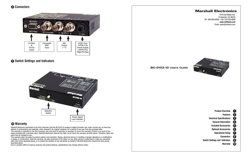
Switch Settings and Indicators
COLOR BAR ON/OFF SWITCH
ILLUMINATES WHEN BARS ARE ACTIVE.
NOTE THAT INPUT SIGNAL WILL NOT
APPEAR WHEN ACTIVATED. BAR SIGNAL
TYPE WILL CHANGE WITH VIDEO FORMAT.
POWER ON/OFF SWITCH
WITH SYSTEM INDICATOR
IF THERE IS NO INPUT SIGNAL, THE
INDICATOR WILL BE AMBER
SWITCH 1
PEDESTAL ON (+) ADDS 7.5 IRE SETUP TO VIDEO SIGNAL
SWITCH 2
UV COMPONENT PROCESS OUTPUT LEVEL SELECTION OF 1000MV (+) OR 700MV (-)
SWITCH 3
CLAMP POSITION ON VIDEO SIGNAL. FRONT PORCH (+), BACK PORCH (-)
SWITCH 4
CLAMP DELAY DIRECTION. POSITIVE (+), NEGATIVE (-)
7
8
7
9
9
1. Unpack the BC-0301-10 and accompanying
V-PS6-1.2A power supply. Physically inspect
for any damage that may have occurred dur-
ing shipping. Also verify there is a small pack-
age with mounting accessories. Should there
be any damage, immediately contact Marshall
Electronics at 800-800-6608. If you are not
located within the continental united states call
+1 310-333-0606.
2. Install in your desired location. If wall
mounting is required, attach the mounting
brackets by removing the Phillips head screws
on the sides, closest to the rear of the unit.
(See Picture) Only one screw per side should
be removed. Use the same screw to attach the
bracket with the flange facing away from the side and parallel to the front of the BC-
0301-10 metal case. The flange has two holes. For desktop use, apply the supplied
rubber pads.
3. Connect required cables for signal input and output.
Please note that power must be applied to the BC-0301-10 for the SDI Output to be
activated. All BNC connectors should be rated for 75Ω.
4. Plug the V-PS6-1.2A power supply into the A.C. source
5. Attach twist lock power connection from V-PS6-1.2A power supply to the back of
the unit.
6. Turn on the BC-0301-10 by depressing the power switch located on the front of the
unit. Refer to Page 4 picture for location of switch settings.
Connectors
Product Overview
Marshall’s cost effective BC-0301-10 digital to analog module can be configured for use in a variety
of applications. The unit features two simultaneous Composite Video and S-Video D/A (10 bit) conver-
sion from a Serial Digital Interface (SDI) signal conforming to SMPTE-259M-C for transport and ITU-
R.BT656/ITU-R601 for video process. 4x over sampling provides superb analog images and up sam-
ples 4:2:2 components to 4:4:4 for processing. There is also a built in Color Bar Generator, System
indicator (PAL/NTSC), and dipswitch settings for Pedestal (On/Off), UV Level Control (700ma/1000ma),
Clamping Position (Front Porch/Back Porch), and Clamping Delay Position (Positive/Negative). All
Marshall Electronics Processing and Distribution modules include power supply and owners manual.
An optional base holder (V-CB1) is available for use in desktop applications.
Electrical Specifications
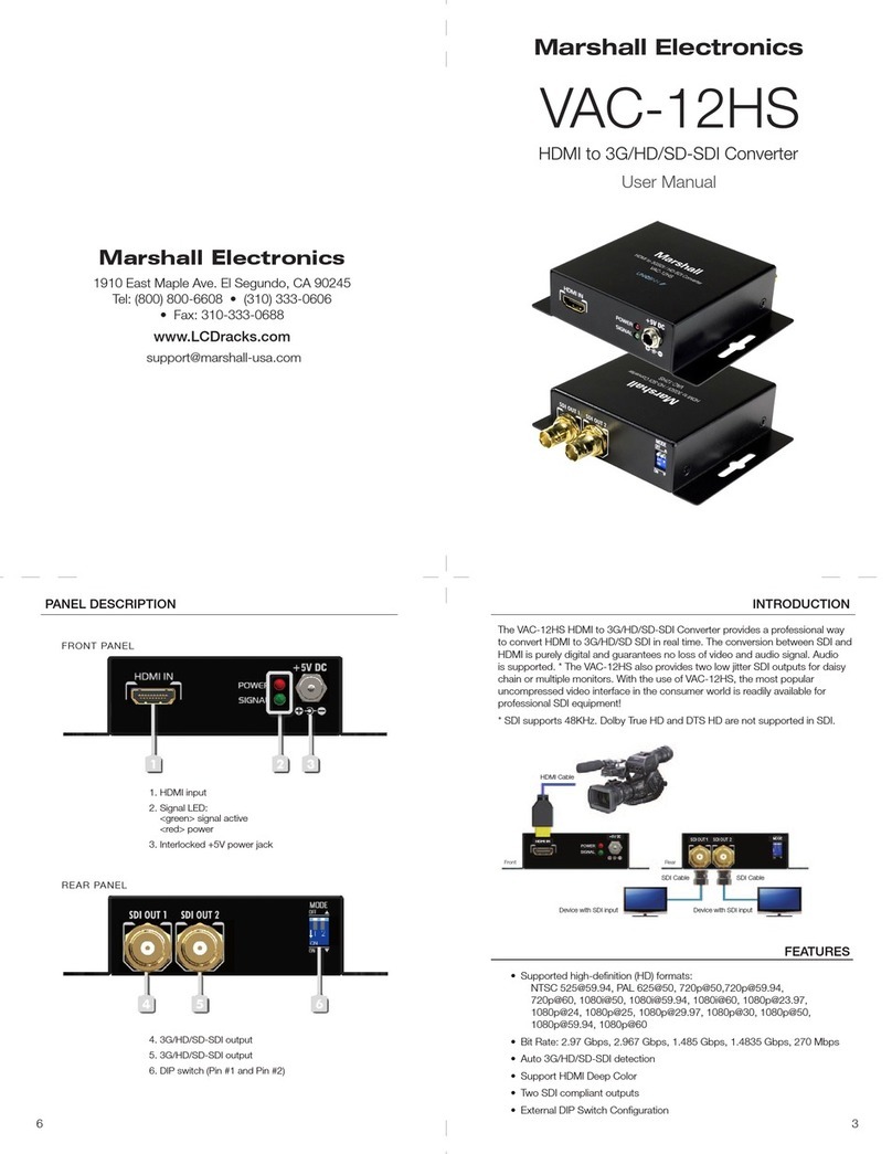
Serial Digital Input 75Ω BNC connection of component digital 525/625 signals conforming to
SMPTE-259M-C, ITU-R.BT656/ITU-R601
Input Data Rate 270 Mb/s
Serial Digital Output BNC active loop through 0.8V p-p 75Ω
Input Return Loss <19db
Input Cable Length 1000’ max (8281 or equivalent)
Analog Output 2 ea. BNC composite video plus simultaneous Y/C (Svideo)
NTSC: 1.0Vp-p 75Ω; PAL: 1.0Vp-p 75Ω conforms to SMPTE-RS-170A
Sample Frequency 54Mhz
Signal to Noise >78db
Differential gain/phase <0.1% / 0.2o
Y/C delay <1%/1o
Power required 6 V D.C. from external power supply (included) max 1.2 AMP
Mechanical Specifications
Dimensions 4.75”W x 3.75”D x 1.0”H (12.1cm x 9.5cm x 2.5cm)
BC-0301-10 Weight 0.80 lbs (0.36kg)
V-PS6-1.2A Power Supply Weight 0.20 lbs (0.10kg)
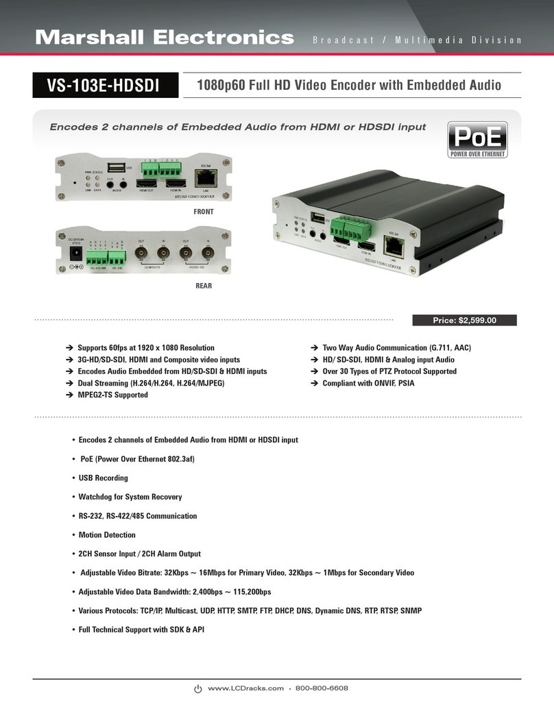
• Cost effective solution for DTV and Multimedia Applications
• Converts component serial digital signal to analog composite
• Active loop through for SDI signal with re-clocking and signal shaping
• Automatic Compensation of SDI input for cable length up to 1000’
• Simultaneous outputs for 2 video and 1 Y/C (S-video)
• PAL/NTSC auto detection with led indicator
• Pedestal on/off selection for NTSC signals
• 10-bit processing with 4x over sampling
• Supports closed captioning
• Includes color bar generator
• Includes Power Supply Model V-PS6-1.2A
23
BC-0301-10 Users Guide Marshall Electronics
ANALOG
VIDEO
OUT 1 BNC
ANALOG
VIDEO OUT 2
S-VIDEO OUT
4PIN DIN
(FEMALE)
PIN1-GND
PIN2-GND
PIN3-YOUT
PIN4-COUT
SDI OUT
RECLOCKED &
SHAPED SIGNAL
REQUIRES
POWER TO BE
APPLIED FOR
ACTIVATION
6 VDC
FROM
V-PS6-1.2A
POWER SUPPLY
LEFT PIN-POS
RIGHT PIN-NEG
V-CB1 Stand
Operational Setup
Optional Accessories
POWER SUPPLY V-PS6-1.2A
BC-0301-10 on V-CB1 Stand
Features
7
1
7
2
7
3
7
5
7
6
7
7
7
4
Other Marshall Electronics Media Converter manuals

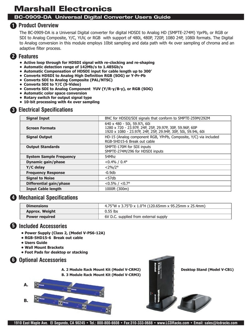
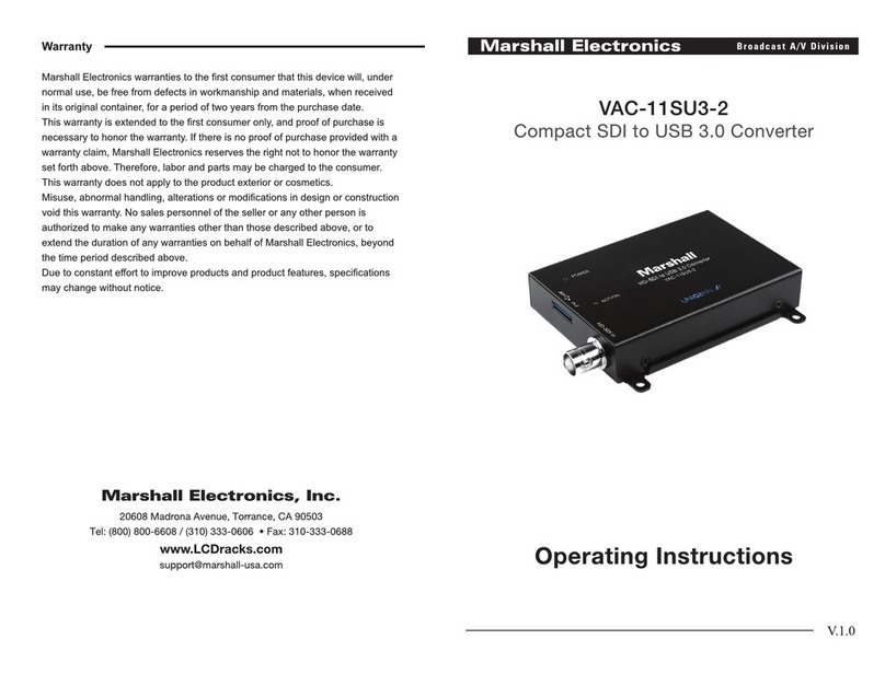
Marshall Electronics BC-0909-DA User manual

Marshall Electronics

Marshall Electronics BC-0909-DA User manual

Marshall Electronics VS-104D-3GSDI User manual

Marshall Electronics

Marshall Electronics VS-104D-3GSDI User manual

Marshall Electronics VAC-11HU3-2 User manual

Marshall Electronics

Marshall Electronics VAC-11HU3-2 User manual

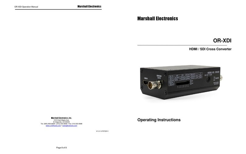
Marshall Electronics OR-XDI User manual

Marshall Electronics

Marshall Electronics OR-XDI User manual

Marshall Electronics VS-103E-HDSDI User manual

Marshall Electronics

Marshall Electronics VS-103E-HDSDI User manual

Marshall Electronics VAC-12HS User manual

Marshall Electronics

Marshall Electronics VAC-12HS User manual

Marshall Electronics VAC-11SU3-2 User manual

Marshall Electronics

Marshall Electronics VAC-11SU3-2 User manual

Marshall Electronics BC-0909-AD User manual

Marshall Electronics

Marshall Electronics BC-0909-AD User manual

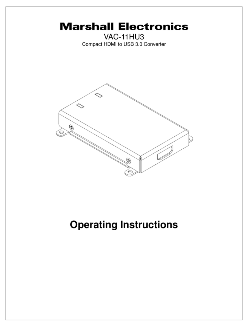
Marshall Electronics VAC-11HU3 User manual

Marshall Electronics

Marshall Electronics VAC-11HU3 User manual

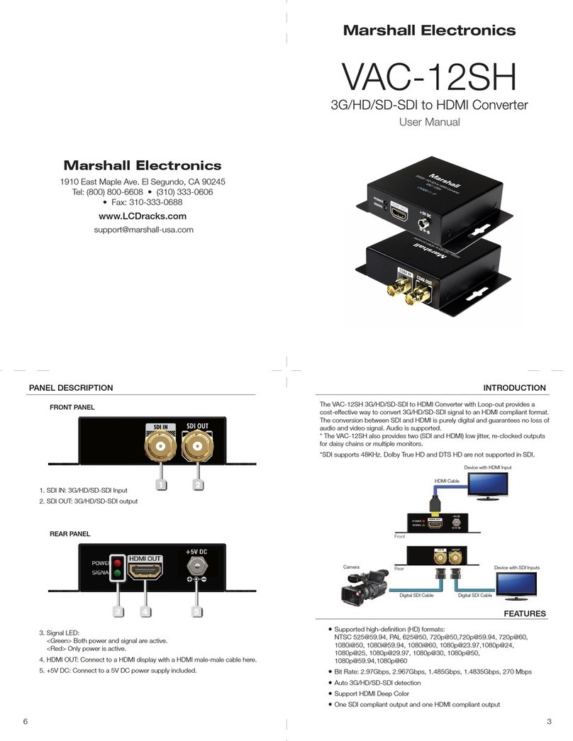
Marshall Electronics VAC-12SH User manual

Marshall Electronics

Marshall Electronics VAC-12SH User manual

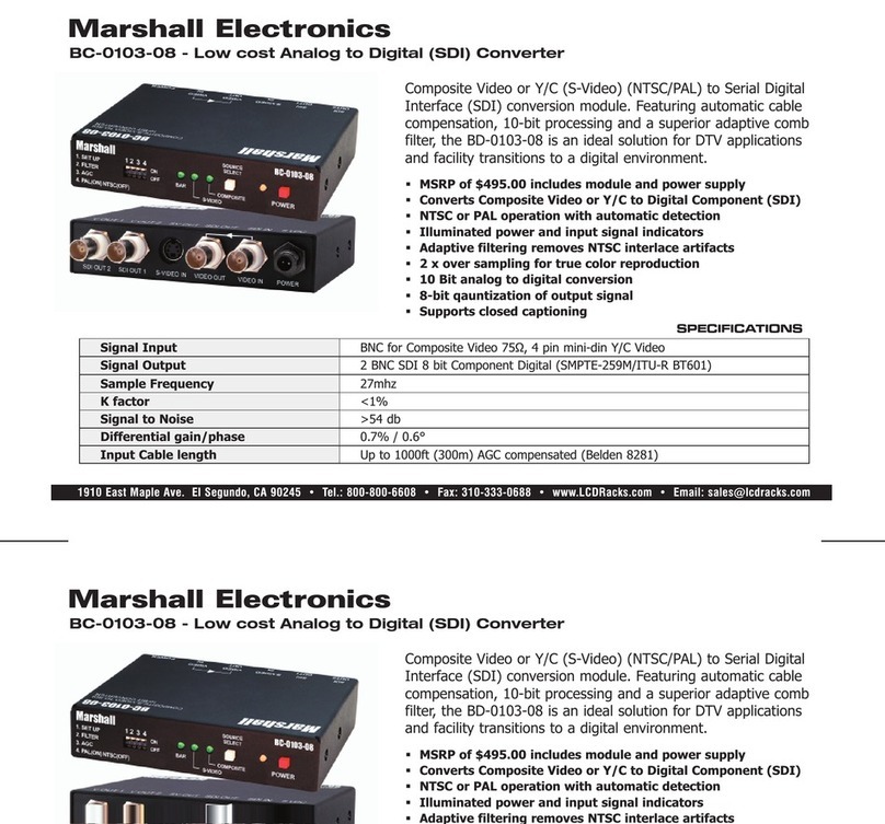
Marshall Electronics BC-0103-08 User manual

Marshall Electronics

Marshall Electronics BC-0103-08 User manual

Marshall Electronics VS-104-3GSDI User manual

Marshall Electronics

Marshall Electronics VS-104-3GSDI User manual

Marshall Electronics BC-0103-10 User manual

Marshall Electronics

Marshall Electronics BC-0103-10 User manual

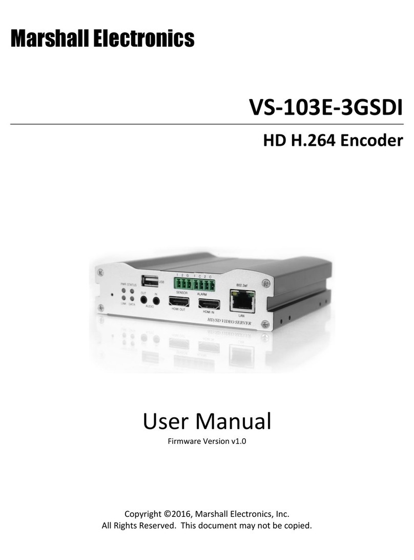
Marshall Electronics VS-103E-3GSDI User manual

Marshall Electronics

Marshall Electronics VS-103E-3GSDI User manual

Marshall Electronics VAC-11SU3 User manual

Marshall Electronics

Marshall Electronics VAC-11SU3 User manual

Marshall Electronics VS-11 User manual

Marshall Electronics

Marshall Electronics VS-11 User manual

Popular Media Converter manuals by other brands

SIIG HDMI to VGA & Audio Converter Scaler installation guide

SIIG

SIIG HDMI to VGA & Audio Converter Scaler installation guide

Audio Note DAC1.1x Owner's Information

Audio Note

Audio Note DAC1.1x Owner's Information

Kübler RLI200 installation manual

Kübler

Kübler RLI200 installation manual

Transition Networks J/E-PSW-FX-02(SC) user guide

Transition Networks

Transition Networks J/E-PSW-FX-02(SC) user guide

ICPDAS tM-7530 quick start guide

ICPDAS

ICPDAS tM-7530 quick start guide

AJA V2Digital Installation & operation guide

AJA

AJA V2Digital Installation & operation guide

TRENDnet TFC-1000MSC D1 Quick installation guide

TRENDnet

TRENDnet TFC-1000MSC D1 Quick installation guide

Sony TDM-NC1 - Wi-fi Client For Streaming Music Specifications

Sony

Sony TDM-NC1 - Wi-fi Client For Streaming Music Specifications

IMC Networks PSE-McBasic Series features and benefits

IMC Networks

IMC Networks PSE-McBasic Series features and benefits

Kiloview N3 user manual

Kiloview

Kiloview N3 user manual

Verint nextiva s1800e series user guide

Verint

Verint nextiva s1800e series user guide

Lenz Digital plus LE010XF manual

Lenz

Lenz Digital plus LE010XF manual

Marshall Amplification RS7-HR installation guide

Marshall Amplification

Marshall Amplification RS7-HR installation guide

MSB Technology The Reference DAC user guide

MSB Technology

MSB Technology The Reference DAC user guide

RGBlink Q Series quick start

RGBlink

RGBlink Q Series quick start

HQ Power HQM119C user manual

HQ Power

HQ Power HQM119C user manual

Transition Networks CPSVT26XX Specifications

Transition Networks

Transition Networks CPSVT26XX Specifications

StarTech.com UVCHDCAP quick start guide

StarTech.com

StarTech.com UVCHDCAP quick start guide

manuals.online logo
manuals.online logoBrands
  • About & Mission
  • Contact us
  • Privacy Policy
  • Terms and Conditions

Copyright 2025 Manuals.Online. All Rights Reserved.