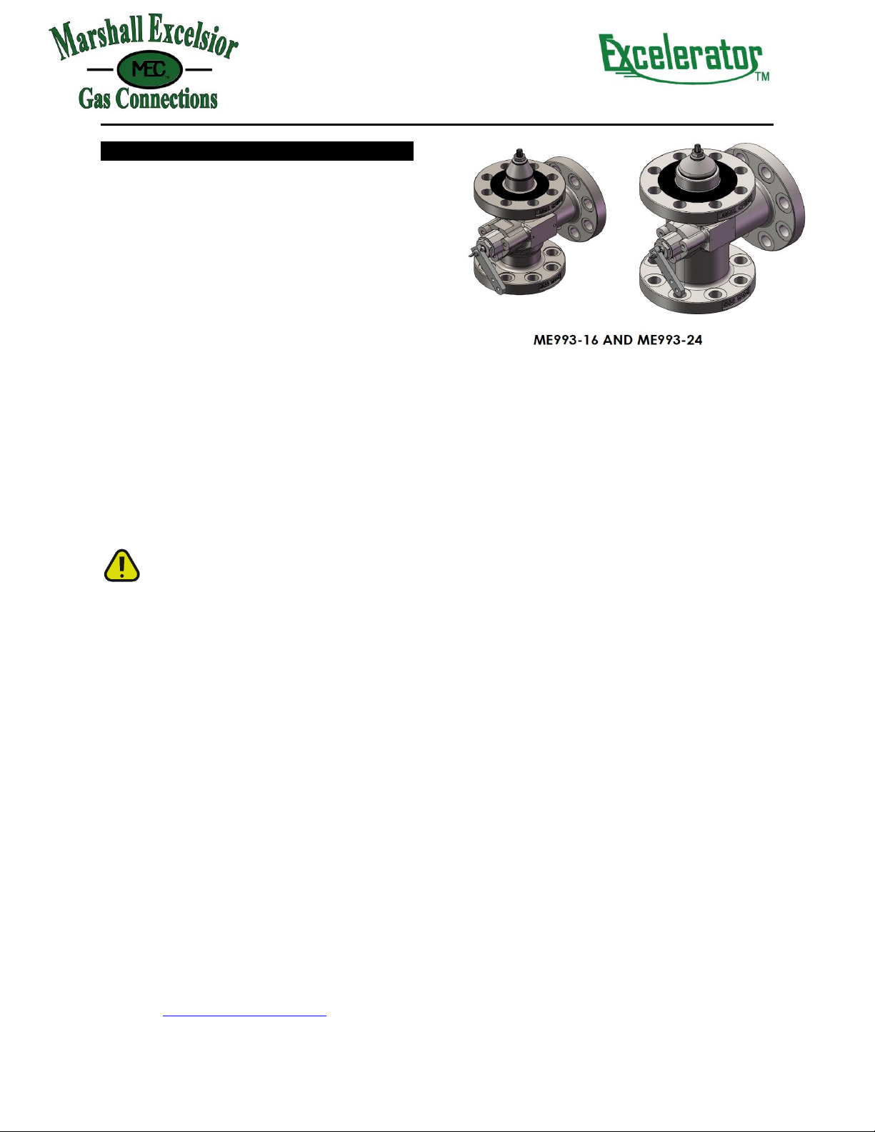
ME993-16 and ME993-24
Form #999 IOM 993-16 & ME993-24 Rev C 5/8/19
The operating linkage must allow the operating lever to
move from the fully closed position to within 2° of the fully
open position. The linkage should not apply strong force to
the lever past the fully open position or the valve could be
damaged.
NOTE
The use of non-MEC actuators may result in leakage of
the gland packing caused by premature wear. In addition
to premature wear, the use of non-MEC actuators may
result in lower than expected flow rates and possible
leakage across the valve seats.
!CAUTION!
The internal valve's closing spring is not designed to
overcome drag in the control linkage in order to close the
valve. Depending upon the control system used, an
external spring or positive closing linkage may be
needed. Be sure the control system is installed to prevent
binding that could cause the valve to stick in the open
position.
Excess Flow Operation
The internal valve contains an excess flow function, or
"integral excess flow valve," that is designed to close when
the flow exceeds the flow rating established by MEC.
MEC's integral excess flow valves installed on a bobtail
truck or transport can provide protection against the
discharge of hazardous materials during an unloading
operation of a bobtail truck or transport in the event that
the pump or piping attached directly to the internal valve
is sheared off before the first valve, pump, or fitting
downstream of the internal valve, provided that the cargo
tank pressure produces a flow rate greater than the valve's
excess flow rating.
Likewise, if the internal valve is installed on a stationary
tank or in the related downstream piping system, the
integral excess flow valve can provide protection against
an unintentional release of hazardous materials in the
event that a pump or piping attached directly to the
internal valve is sheared off before the first valve, pump,
or fitting downstream of the internal valve, provided that
the flow of product through the internal valve reaches the
rated flow specified by MEC.
!EXPLOSION HAZARD!
Restrictions incorporated in the discharge system of a
bobtail truck or transport or of a stationary tank (due to
pumps, pipe and hose length and dimensions, branching,
elbows, reductions in pipe diameter, or a number of
other inline valves or fittings), low operating pressure as
a result of ambient temperature, or a partially closed
valve downstream from the integral excess flow valve,
can restrict the rate of flow through the internal valve
below the level necessary to actuate the integral excess
flow valve. Therefore, DO NOT USE the excess flow
function of the internal valve for the purpose of providing
protection against the discharge of hazardous materials
in the event of a rupture of hose or piping at a point in
the discharge system downstream from the first valve,
pump, or fitting downstream of the internal valve.
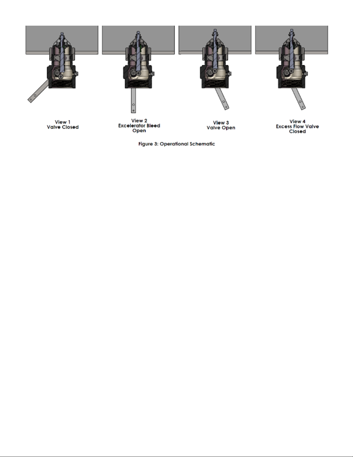
The internal valve is designed with an internal bleed
feature for equalization of pressure. After the integral
excess flow valve closes, the leakage through the bleed
must be controlled or a hazard can be created. For this
reason the operator must be familiar with the closure
controls for the internal valves and must close the
internal valve immediately after the integral excess flow
valve closes.
Failure to follow this warning could result in serious or
fatal personal injury or property damage from a fire or
explosion.
DOT Passive Shutdown Equipment Requirement -
DOT regulations 49 CFR§173.315(n)(2) require certain
cargo tanks transporting propane, anhydrous ammonia
and other liquefied compressed gases to be equipped with
passive emergency discharge control equipment that will
automatically shut off the flow of product without human
intervention within 20 seconds of an unintentional release
caused by complete separation of a delivery hose. The
design for each passive shutdown system must be certified
by a Design Certifying Engineer (DCE) and all components
of the discharge system that are integral to the design
must be included in the DCE certification. The DCE
certification must consider any specifications of the
original component manufacturer. In the case of
downstream ruptures in hose or piping, a variety of
operating conditions routinely encountered during an
unloading operation restrict the rate of flow through the
integral excess flow valve and make such a valve
unsuitable to serve as the means of passive shutdown
required under 49 CFR§173.315(n)(2). Such variables
include restrictions incorporated in the discharge system
(due to pumps, pipe and hose length and dimensions,
branching, elbows, reductions in pipe diameter, or a
number of other in-line valves or fittings), low operating
pressure as a result of ambient temperature, or a partially
closed valve downstream from the excess flow valve. Due
to the variety of conditions, in the case of a hose
separation, that can restrict the rate of flow below the
level necessary to activate the excess flow valves, the
integral excess flow function of MEC ME993 internal valves
cannot be used to satisfy the passive shutdown equipment
requirement under/in 49 CFR§173.315(n)(2). Also, a
Design Certifying Engineer cannot include the integral
excess flow valve of a MEC ME993 internal valve as a
component of the discharge system in any DCE
certification under 49 CFR§173.315(n)(2).
!EXPLOSION HAZARD!
DO NOT USE the excess flow function incorporated into
MEC ME990 internal valves to satisfy the passive
shutdown equipment requirement in 49
CFR§173.315(n)(2). DO NOT include the excess flow
function incorporated into MEC ME990 internal valves in
a DCE certification under 49 CFR§173.315(n)(2). The cargo
tank manufacturer must install some other equipment
that satisfies the requirement for passive shutdown
capability under 49 CFR§173.315(n)(2).