8 of 16
104 S. 8th Ave. Marshalltown, IA Phone 800-888-0127 / 641-753-0127 • Fax 800-477-6341 / 641-753-6341 www.
marshalltown
.com
WS570
R10-15-12
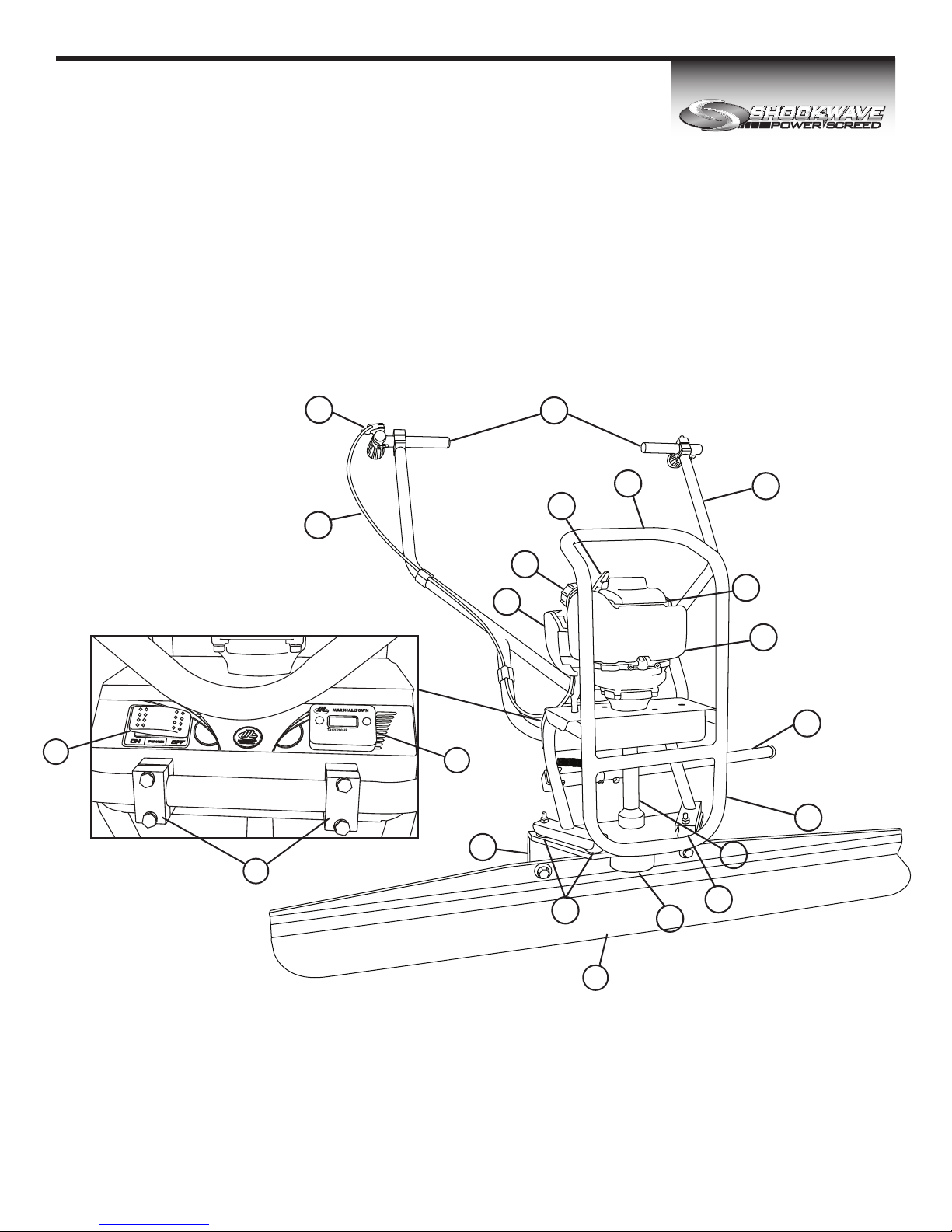
DETAIL A
A
16
46
44
20
45
3
1
17
5
22
24
4
33
19
39
7
8
29
9
11
30
35
32
27
31
12
34
28
47
47
2
23
43
26
48
17
18
2
2
15
21
10
13
14
33
25
37
38
41
36
42
40
49
6
DET. QTY. DESCRIPTION
1 1 GX35 HONDA MOTOR
2 8 HANDLEBAR CLAMP
3 1 HANDLEBAR ASSEMBLY
4 1 BASE EXTRUSION
5 1 TACHOMETER
6 1 KILL SWITCH
7 4 VIBRATION ISOLATOR
8 1 ECCENTRIC WEIGHT #1
9 1 ECCENTRIC WEIGHT #2
10 1 ECCENTRIC SHAFT
11 1 ECCENTRIC WEIGHT BUSHING
12 1 WEIGHT ADJUSTMENT CAP
13 1 LOWER BEARING HOUSING
14 1 COUPLING DRIVE SHAFT
15 1 CLUTCH
16 1 FLEX SHAFT
17 1 HANDLEBARS, L-GRIP
18 1 HANDLEBARS, T-GRIP
19 2 BLADE ATTACHMENT NUT
20 1 BLADE
21 1 KICKSTAND END
22 1 KICKSTAND ARM
23 2 KICKSTAND EYEBOLT
24 1 KICKSTAND END CAP
25 1 SPRING
26 1 FRAME
27 1 ECCENTRIC COVER
28 1 ECCENTRIC COVER CAP
29 3 DRIVETRAIN BASE MOUNTING SCREW
30 1 ECCENTRIC WEIGHT JAM NUT
31 1 ECCENTRIC TIGHTENING CAP BOLT
32 2 BLADE ATTACHMENT BOLT
33 4 ECCENTRIC COVER MOUNTING SCREW
34 4 ECCENTRIC CAP SCREW
35 8 VIBRATION ISOLATOR NUT
36 4 WELD NUT FOR HANDLEBAR CLAMPS
37 2 TACHOMETER MOUNTING SCREW
38 2 TACHOMETER MOUNTING NUT
39 4 VIBRATION ISOLATOR NUT
40 2 BLADE ATTACHMENT LOCK WASHER
41 8 HANDLEBAR CLAMP BOLT
42 2 KICKSTAND NUT
43 2 KICKSTAND BOLT
44 1 REPLACEMENT DRIVESHAFT CORE (NOT PICTURED)
45 1 THROTTLE LEVER ( FRICTION STYLE)
46 4 ENGINE MOUNTING BOLTS
47 2 HANDLEBAR GRIPS
48 1 THROTTLE CABLE
49 1 KILL SWITCH WIRING
REPLACEMENT PARTS INDEX
EDI PART# DESCRIPTION DETAILS INCLUDED
13308 13308 HANDLES WITH GRIPS 17, 18, 47
13309 13309 GRIPS 47
13310 ENG-HONDA HONDA ENGINE 1, 46
13312 13312 THROTTLE LEVER 45
13313 13313 THROTTLE CABLE 48
13314 13314 HANDLEBARS 3
13315 13315 HANDLEBAR CLAMPS W/HARDWARE 2, 41
13316 13316 HANDLEBAR CLAMP HARDWARE ONLY 41
13317 13317 ON/OFF SWITCH W/WIRES 6, 49
13318 13318 ON/OFF SWITCH WIRES 49
13319 13319 TACHOMETER 5, 37, 38
13320 13320 ECCENTRIC COVER W/HARDWARE 27, 28, 33, 34
13321 13321 KICKSTAND 21, 22, 23, 24, 25, 42, 43
13322 13322 KICKSTAND HARDWARE 23, 25, 42, 43
13323 13323 DRIVE TRAIN 10, 13, 14, 16, 29, 44
13324 13324 CLUTCH 15, 46
13325 13325 VIBRATION DAMPENING KIT 7, 35, 39
13330 13330 ECCENTRIC WEIGHTS & HARDWARE 8, 9, 11, 12, 30, 31
13331 13331 ECCENTRIC WEIGHT HARDWARE ONLY 11, 12, 30, 31
13332 13332 MACHINE BASE 4
13333 13333 BLADE LOCKING HARDWARE 19, 32, 40
13334 13334 DRIVE SHAFT 44
13335 13335 DRIVE SHAFT HOUSING 10, 13, 14, 16
12951 12951 FRAME ONLY 26
12952 12952 ECCENTRIC COVER HARDWARE ONLY 33, 34
PARTS BREAKDOWN