Marson MR10A7 User manual

-1-
marson
MR10A7
Mobile NFC Reader
User’s Manual
V 1.2
2015 / 1 / 27

-2-
- Table of Contents -
1. Introduction...................................................................................................................................................... 4
1-1. Product Features......................................................................................................................................... 4
1-2. Package Contents ....................................................................................................................................... 5
1-3. Product Characteristics and Specifications................................................................................................... 5
1-3-1. NFC Tags Supported by the MR10A7 ................................................................................................ 5
1-3-2. MR10A7 Product Specifications ........................................................................................................ 6
1-3-3. MR10A7 Indicator Lights and Sounds................................................................................................ 7
1-4. Operating Instructions ................................................................................................................................ 8
1-4-1. Power Up.......................................................................................................................................... 8
1-4-2. Shut Down........................................................................................................................................ 8
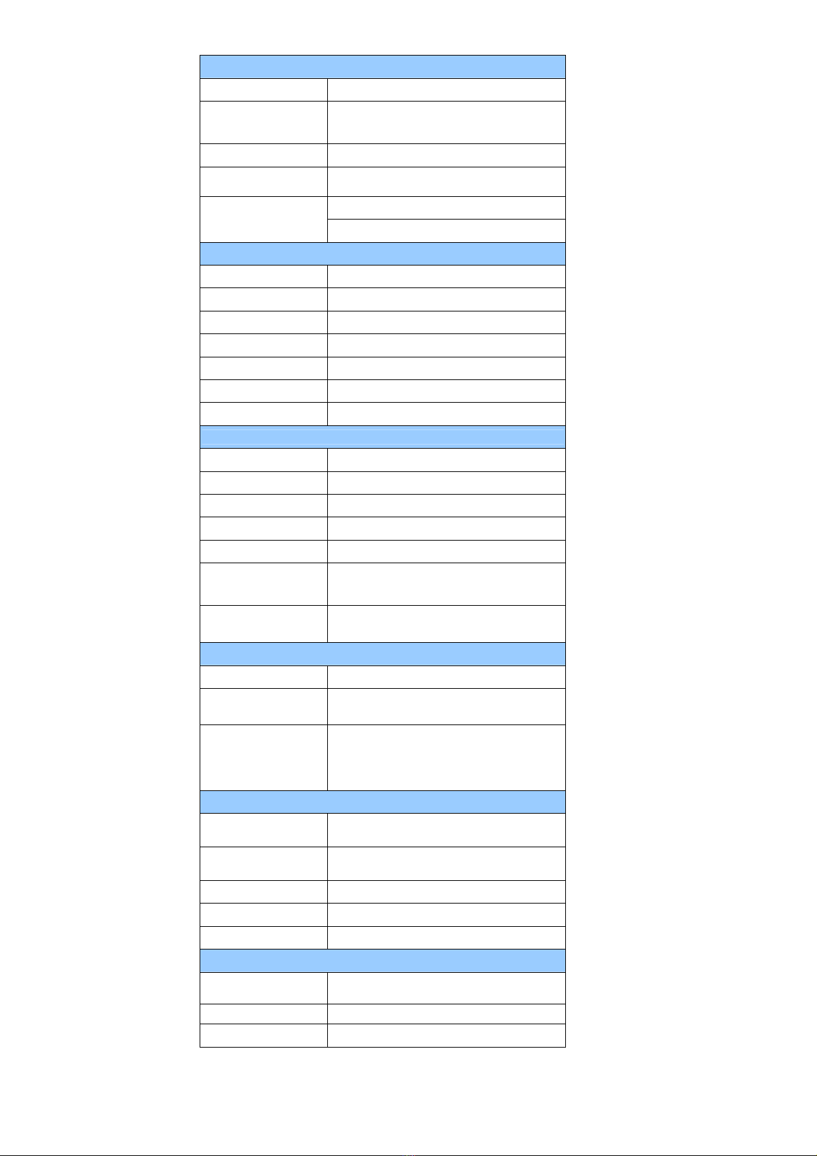
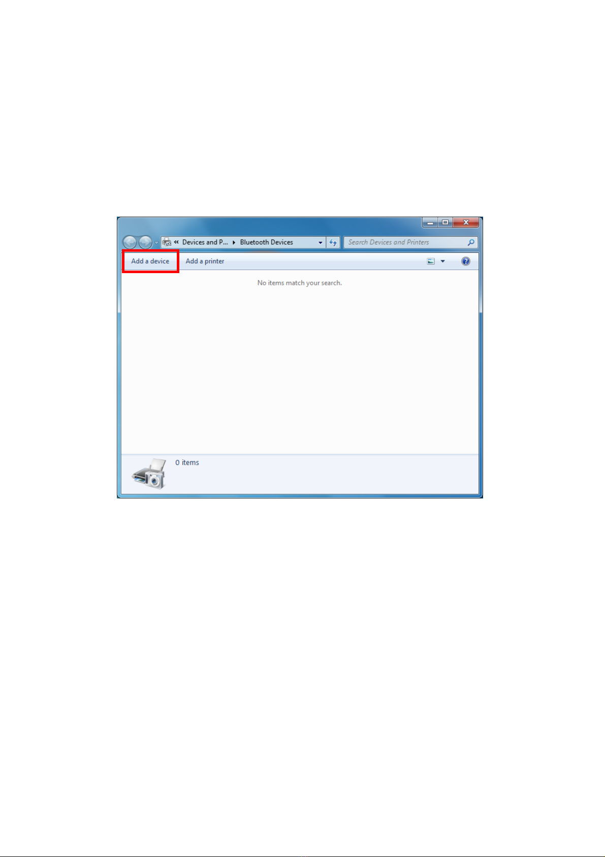
1-4-3. Connecting to a PC/ Notebook .......................................................................................................... 9
1-4-4. Connecting to an Apple iOS Device ................................................................................................. 12
1-4-5. Connecting to an Android Device.................................................................................................... 15
1-4-6. Reading NFC Tags ........................................................................................................................... 18
1-4-7. Clearing the Bluetooth Pairing Record........................................................................................... 20
1-4-8. Storing/Deleting Memory Data ..................................................................................................... 21
2. Configuration Mode ........................................................................................................................................ 25
2-1. Entering Configuration Mode ..................................................................................................................... 25
2-2. Canceling / Exiting Configuration Mode .................................................................................................... 26
3. Operating the MARSON RFID Utility ................................................................................................................ 27
3-1. Introduction to Main Window................................................................................................................... 27
4. RFID Parameters Setup.................................................................................................................................. 29
4-1. Operation Mode ........................................................................................................................................ 29
4-2. Tag Info ....................................................................................................................................................... 30
4-3. Session Time and Delay Time...................................................................................................................... 31
4-3-1. Session Time Operation Method .................................................................................................... 31
4-3-2. Delay Time Operation Method ....................................................................................................... 31
4-4. Select Tag Category.................................................................................................................................... 31
4-5. Data Output Format .................................................................................................................................. 32
4-5-1. Time Log.......................................................................................................................................... 33
4-5-1-1. Configure whether to output Time Log’s Caption “Time Log”: ......................................... 33
4-5-2. Tag Name......................................................................................................................................... 33
4-5-2-1. Configure whether to output Tag Name’s caption “Tag
Name”: ........................................ 33
4-5-3-1. Configure whether to output AFI caption “AFI”.................................................................. 34
4-5-4. DSFID Data....................................................................................................................................... 34
4-5-4-1. Configure whether to output DSFID’s caption “DSFID” ....................................................... 34
4-5-5. UID Data .......................................................................................................................................... 34
4-5-5-1. Configure whether to output UID caption “UID”................................................................ 34
4-5-6. Data Block Output ............................................................................................................................ 35
4-5-7. No Tag Message............................................................................................................................... 35
5. Other Parameters Setup .................................................................................................................................. 36
5-1. Date Format............................................................................................................................................... 36
5-4. Memory Communication Interface Options ............................................................................................... 39
5-4-1. Field Separator ............................................................................................................................... 39
5-4-2. Storage Sequence............................................................................................................................ 39
5-5. BT-HID and BT-SPP Communication Interface Options ............................................................................... 40
5-5-1. BT-ID ................................................................................................................................................ 40
5-5-2. BT-Pin-Code ..................................................................................................................................... 40

-3-
5-6. USB-HID and BT-HID Communication Interface Options............................................................................. 40
5-6-1. Keyboard Layout............................................................................................................................. 40
5-6-2. Key Numeric .................................................................................................................................... 40
5-6-3. Key Caps Lock .................................................................................................................................. 40
5-6-4. Inter-black Interval Time ................................................................................................................ 40
5-6-5. Inter-character Interval Time ......................................................................................................... 40
5-7. Data Terminator......................................................................................................................................... 41
5-8. Sleep Mode / Timer................................................................................................................................... 41
5-8-1. Enter Sleep Mode............................................................................................................................ 41
5-8-2. Timer of Sleep Mode....................................................................................................................... 41
5-9. Buzzer ........................................................................................................................................................ 42
5-9-1. Beep Tone........................................................................................................................................ 42
5-9-2. Beep Time ....................................................................................................................................... 42
5-10. Vibrator ................................................................................................................................................... 42
5-11. Waiting Time ........................................................................................................................................... 43
5-12. System Time ............................................................................................................................................ 43
6. Additional Functions ........................................................................................................................................ 44
6-1. System ........................................................................................................................................................ 44
6-2. Operation................................................................................................................................................... 46
6-3. Tools ........................................................................................................................................................... 47
7. Updating Firmware on MR10A7....................................................................................................................... 48
7-1. Entering Firmware Update Mode.............................................................................................................. 48
7-2. Executing Firmware Update ...................................................................................................................... 49

-4-
1. Introduction
The MR10A7 is a Wireless NFC Reader that uses Bluetooth as the communication interface. It can quickly
connect with computers, mobile phones, tablets, etc. through the Human Interface Device (HID), without
installing additional device drivers, and can complete an array of operations by integrating its Apps with the
Cloud. With a streamlined contemporary styling and a fresh, simple, two colour design, it is ergonomic and
easily fits in one hand. With an IP55 dust and water protection rating and a 1.5 meter fall-protection rating, it is
also suitable for prolonged use outdoors and in various harsh environments. The MR10A7 has a 1000mAh
internal battery and 2MB of internal memory, enough for 10,000 online/offline scans. It can also read from the
entire lineup of high frequency RFID NFC chips (ISO14443A, ISO14443B, ISO15693), including wireless key cards,
debit cards, and the commonly seen EasyCard.
1-1. Product Features
Light and Easy to Carry
Using Bluetooth as the communication interface, the MR10A7 avoids wiring limitations and enables users to
transfer and sync data without changing their work style. Weighing in at just 70g, the product is easily held in
one hand and is shaped ergonomically.
Novel Exterior Design
The two-colour exterior design is fresh, simple and clean. The unibody plastic shell is curved, fashionably
shaped, and in harmony with mobile phones and tablet usage.
Industry Level Protection
The MR10A7 is an RFID Wireless Reader featuring IP55 dust and water protection rating and a 1.5 meter fall
protection rating. It is suitable for prolongs use outdoors or in extremely harsh environments.
High Performance Reading
The MR10A7 can read all RFID high frequency chipsets (ISO1443A, ISO1443B, ISO15693 and NFC), including
wireless key cards, debit cards, and the often-seen EasyCard
Excellent Compatibility
Featuring Secure Simple Paring (SSP), the MR10A7 is compatible with the various mobile phones and tablets
in the market. The user simply taps on the screen to connect via Bluetooth Human Interface Device (HID)
—no pincode required.
Long Battery Life
The 1000mA internal lithium battery powers up to 10,000 scans on a full charge, eliminating the need for
frequent battery changes, ensuring employee efficiency.
Human Centred Design
Streamlined, simple button and indicator light design saves users from spending time fumbling. The unique
mode indicator light and vibrator communicates read status to the user even in noisy surroundings. A
detachable hand strap is also included, so the device may be tied to the waist or hung on the neck, making it
easy to reach for anytime use, and hard to lose.

-5-
1-2. Package Contents
Each MR10A7 package includes the following items:
1.
MR10A7 Wireless NFC Reader
2.
One (1) Hand Strap
3.
One (1) Micro USB cable
1-3. Product Characteristics and Specifications
1-3-1. NFC Tags Supported by the MR10A7
The MR10A7 can scan the entire series of high frequency NFC tags, including those
supporting NFC standards like ISO14443A, ISO14443B, ISO15693, etc. Common NFC tags
are listed in Table 1-1*.
Standard Tag name
Mifare S-70
Mifare S-50
Mifare Ultralight
Mifare DesFire (MF3)
ISO14443A
SLE66R35 (M-Classic)
SRIX512
ISO14443B SRIX4K
I-Code SLI
Ti2048 (Plus)
Ti256 (Standard)
SRF55V10P (EM)
ISO15693
Advant ATC1024
Topaz 96/ 512
Felica
Felica Lite
Others
NTAG 203/ 215/ 216
Table 1-1: NFC Tags supported by the MR10A7
* The contents of this table are subject to change,
without notice, following technical development.

-6-
1-3-2. MR10A7 Product Specifications
Performance
Frequency 13.56MHz
Standard ISO 15693
ISO 14443
Memory 2 MB
Read Mode Single read
ISO 14443: 0~25mm
Reading Distance ISO 15693: 0~50mm
Physical Characteristics
Dimension W42.5×L102×H21.5 mm
Weight 70g
Color White
Material PC
Cable 1.5 M (Micro USB cable)
Trigger Scan Button, iOS Hotkey
Indicator Buzzer, LED, Vibrator
Power
Operation Voltage 3.7 VDC
Working Current < 250mA
Standby Current < 75mA
Idle Current < 1mA
Surge Current < 700mA
Battery 3.7V, 1000mAh, Lithium Battery
Number of Scan
(per full charge) > 10,000 scans
(1 scan/ 5 secs, Bluetooth connected)
Connectivity
Radio Bluetooth 2.1 + EDR (Class2)
Range 10m (line of sight)
Interface/ Profile
BT (SPP)
BT (HID)
USB (HID)
USB (VCP)
User Environment
Operating
Temperature -10~50˚C
Storage
Temperature -20~60˚C
Humidity 0%~95%RH (Non-condensing)
Drop Durability 1.5M
Sealing IP55
Regulatory
ESD Functional after 4KV contact, 8KV air
discharge
EMC CE, FCC
Safety RoHS 2.0, WEEE
Table 1-2: MR10A7 Specifications

-7-
1-3-3. MR10A7 Indicator Lights and Sounds
MR10A7’s LED indicators use three colours: blue, green and red, as per Figure 1-1. In
combination with the buzzer they indicate different conditions, in Configuration Mode.
Status Blue LED Green LED Red LED Beeper
Power up
lits 1 second 1 long beep
Good Read lits 1 second 1 short beep*
Bluetooth Disconnected (Discoverable) flashing
Bluetooth Connected 2 flashes 2 short beeps
Deletes Pairing Record
2 short beeps
Data Transfer Failure (Offline) lits 1 second
3 short beeps
Data Storage Failure (Memory Full) 1 flash
3 short beeps
Enters Configuration Mode stays on 2 short beeps
Exits Configuration Mode 2 short beeps
Low Power
flashing
Charging
stays on
Table 1-3: MR10A7’s LED Indicators and Beeper
*Please refer to 5-9-2. Beep Time for beep length configuration.

-8-
1-4. Operating Instructions
1-4-1. Power Up
Press the Trigger Button for 2 seconds without releasing, as per Figure 1-1. The unit will emit one (1) long
beep and light the LED red. When the sound then stops and the light goes off, the reader successfully
powers up.
Trigger Button Function Button
Blue/Green/
Red LED
Indicator
Figure 1-1: Trigger Button and Function Button positions
1-4-2. Shut Down
Method 1:
By default, the unit shuts down automatically after 5 minutes of inactivity. To adjust the auto
power-off timeout, please refer to Chapter 5-8. Enter Sleep Mode / Timer
Method 2:
Using a needle or paper clip, press the Reset Button located at the bottom of the MR10A7 once, as
per
Figure 1-2. This will force a shut down.
Figure 1-2: Reset Button position
Reset Button

-9-
1-4-3. Connecting to a PC/ Notebook
Step 1:
Press and hold the Trigger Button for 2 seconds to power up the unit, after which the blue
indicator LED will flash continuously. (If the blue LED does not flash, it means the unit is not
currently in Bluetooth Mode. Please refer to Section 5-3. Communication Interface, and
change the Communication Interface to BT-HID.)
Step 2:
Enter the PC/Notebook’s Bluetooth application, as per Figure 1-3, and click Add a Device.
Figure 1-3: PC/NB Bluetooth application Main Window

-10-
Step 3:
In the Add a device window, double click HF RFID Reader to connect, as per
Figure 1-4.
Figure 1-4: Select Bluetooth Device window

-11-
Step 4:
When successfully connected the MR10A7 will emit two short beeps, and the blue LED
indicator will shut
off. The PC/NB will show a message window like in Figure 1-5, and after
clicking Close the PC/NB
Bluetooth application Main Window will show HF RFID Reader as a
connected device, as per Figure 1-6.
Figure 1-5: Connection Successful message window
Figure 1-6: PC/NB Bluetooth application Main Window
Step 5:
Launch a program that can accept HID keyboard input, such as Notepad. NFC Tag data read
by the
MR10A7 will output to that program

-12-
1-4-4. Connecting to an Apple iOS Device
Step 1:
Press and hold the Trigger Button for 2 seconds to boot the unit, after which the blue LED
indicator will flash continuously. (If the blue LED indicator does not flash, it means the unit is
not currently in Bluetooth Mode for its Communication Interface. Please refer to Section 5-3.
Communication Interface, and change the Communication Interface to BT-HID.)
Step 2:
On the Apple iOS device, go to Settings > Bluetooth, and turn on Bluetooth, as per Figure 1-8.
Figure 1-8: Bluetooth Settings screen

-13-
Step 3:
In the discoverable devices list, select HF RFID Reader, as per Figure 1-9
Figure 1-9: Select HF RFID Reader from the discoverable
devices list.
Step 4:
Upon establishing connection the MR10A7 will emit two short beeps and turn off its blue LED
indicator. Also, the HF RFID Reader will list as “Connected” in the Apple iOS device’s Bluetooth
devices list, as per Figure 1-10.
Figure 1-10: The HF RFID Reader now lists as “Connected”
in the discoverable devices list.

-14-
Step 5:
Launch an app that can accept HID keyboard input, such as Notes. NFC Tag data read by MR10A7
will output to that app, as per Figure 1-11.
Figure 1-11: NFC Tag data will output to an app
Step 6:
If a virtual keyboard is required, please press the Function Button once, as per Figure 1-12. At this
moment
the MR10A7 will emit one short beep, and the Apple iOS device’s virtual keyboard will pop
out.
Trigger Button Function Button
Figure 1-12: Trigger Button and Function Button locations

-15-
1-4-5. Connecting to an Android Device
Step 1:
Press and hold the Trigger Button for 2 seconds to boot the unit, after which the blue LED
indicator will flash continuously. (If the blue LED does not flash, it means the unit is not currently
in Bluetooth Mode. Please refer to Section 5-3. Communication Interface, and change the
Communication Interface to BT-HID.)
Step 2:
On the Android device, go to Settings > Bluetooth, and turn on Bluetooth, as per Figure 1-13.
Figure 1-13: Bluetooth Settings screen
Step 3:
In the available devices list, select HF RFID Reader, as per Figure 1-14.
Figure 1-14: Select HF RFID Reader from the Bluetooth Settings screen.

-16-
Step 4:
Upon establishing connection the MR10A7 will emit two short beeps and turn off its blue LED
indicator. Also, the HF RFID Reader will list as “Connected” in the Apple iOS device’s Bluetooth
devices list, as per Figure 1-15.
Figure 1-15: The HF RFID Reader now lists as
“Connected” in the
Bluetooth setup screen.
Step 5:
Launch an app that can accept HID keyboard input, such as ColorNote. NFC Tag data read by the
MR10A7 will output to that app, as shown in Figure 1-16.
Figure 1-16: NFC Tag data outputs to an app.

-17-
Step 6:
If a virtual keyboard is required, please go to Settings > Language and Input > Default, and turn
off the physical keyboard (or in some cases, turn on the on-screen keyboard) in the Select Input
Method screen, as shown in Figure 1-17. At this time the virtual keyboard will resume normal
operation.
Figure 1-17: Turn on the on-screen keyboard.

-18-
1-4-6. Reading NFC Tags
MR10A7’s RFID antenna is located at its front (as per Figure 1-18). When reading, hold the unit, aim
at
the NFC tag (as per Figure 1-19), and press the Trigger button. If reading is successful (Good
Read), the
MR10A7 will emit one beep and the green LED indicator will simultaneously lit for one
second. Reading Range varies based on NFC tag specifications, as Table 1-4 describes.
Standard Reading Range
ISO 14443A 0~25mm
ISO 14443B 0~25mm
ISO 15693 0~50mm
Others 0~25mm
Table 1-4: Reading Range for Tags of various standards.
Antenna
Blue/Green/Red LED Indicator
Figure 1-18: Antenna, LED, Trigger Button and Function Button locations
Figure 1-19: Aiming at an NFC Tag and Reading Range
Trigger Button Function Button
NFC Tag
Reading Range

-20-
1-4-7. Clearing the Bluetooth Pairing Record
The MR10A7 will save its Bluetooth pairing records and, when disconnected, will automatically
attempt to restore previous connections. The following steps will clear MR10A7’s Bluetooth pairing
record, facilitating
new connections. After clearing its Bluetooth pairing record the MR10A7 will
break off all Bluetooth connections, entering Bluetooth Disconnected status.
Step 1:
Press and hold the MR10A7’s Function button first without releasing, then press and hold the Trigger
button, as per Figure 1-20. Press on both buttons for about 5 seconds and the MR10A7 will emit 2
short beeps and light its LED indicator green. It will then enter the Configuration Mode. Release both
buttons afterwards.
Step 2:
Hold the Trigger button for about 5 seconds and the MR10A7 will light its LED indicator blue; a second
later the MR10A7 will emit 2 short beeps and simultaneously turn off the blue LED indicator, after
which you may release the trigger button. The reader will further emit 2 short beeps and flash its
Green LED once as confirmation that it has cleared its Bluetooth pairing record and exited
Configuration Mode.
Blue/Green/Red LED
Indicator
Figure 1-20: Trigger Button and Function Button locations
CAUTION ! After clearing the Bluetooth connection record the MR10A7 will enter Bluetooth
Disconnected
status and continuously flash its blue LED indicator. If the blue LED indicator does
not flash, it means the unit’s Communication Interface is not in Bluetooth Mode. Please refer to
Section 5-3. Communication Interface.
Trigger Button Function Button

-21-
1-4-8. Storing/Deleting Memory Data
When the Communication Interface is set to Memory (refer to Section 5-3. Communication Interface),
data obtained from NFC Tag read operations will be stored in MR10A7’s memory. The following steps
will store
or delete the data within.
A. Storing the Data in Memory
Step 1:
After completing an NFC Tag read operation, use a micro USB cable and connect the
MR10A7 to a PC/NB.
Step 2
Open the My Computer window and enter the removable storage device “MiniScan”,
as per Figure 1-21.
Figure 1-21: Entering the removable storage device “MiniScan” through My Computer.
Other manuals for MR10A7
1
Table of contents
Other Marson RFID System manuals