Marus TL 500 User manual

TL 500 Track Light
Owner’s Manual
Marus
11727 Fruehauf Drive
Charlotte, NC 28273 USA
Technical Support: 800-304-5332
FAX: 888-861-9366

11727 Fruehauf Drive
Charlotte, NC 28273 USA
Technical Support: 800-304-5332
FAX: 888-861-9366
Warranty
92353 • Rev. 5 • 02/12
All of our products sold to and installed by dealers are guaranteed to be free from defects in workmanship
and materials for ve years from date of purchase. Upholstery is warranted for a period of one year from
the date of purchase. During that period, we will replace any defective part at no charge. We WILL NOT
be responsible for dealer or service company labor charges or shipping charges to the factory.
This guarantee does not cover normal wear, stains, cuts or scratches of upholstery or surface nishes or
parts sold to OEM customers.
Staining, discoloration or deterioration of the equipment caused by disinfectant solutions is not covered
under the warranty.
We will pay the return freight charges from the factory to the dealer. This guarantee does not cover dam-
age resulting from improper installation, misuse or accidents incurred in shipping and handling.
All claims against the freight carrier must be initiated at the time the damaged items are received. The
claim is the responsibility of the customer.
We are constantly striving to improve our products. We reserve the right to make modications without
the need for prior notication and are not obliged to modify previously manufactured items.
Fiber optic system note: Units equipped with the optional ber optic system are covered under the ve
year warranty, although the bulbs are items not covered under warranty and must be purchased.
It is the user’s responsibility to read and understand the contents of this manual. This
manual contains important information relative to hazards to personnel and property if
this equipment is not installed, used and/or maintained as instructed.

1
General Information and Warnings......................................................................................................2
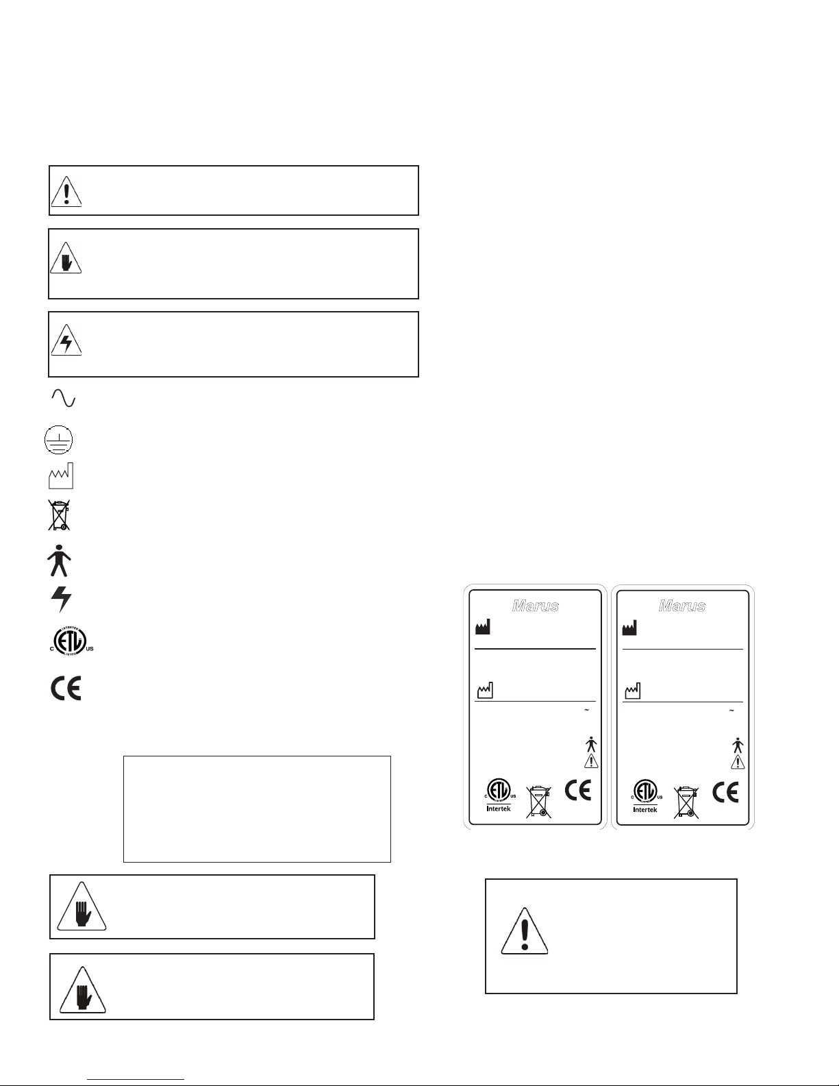
Denition of Symbols.....................................................................................................................2
Product Disposal ...........................................................................................................................2
Interference with Electromedical Devices......................................................................................2
Incompatible Devices and/or Accessories .....................................................................................2
Obtaining Technical Literature .......................................................................................................2
Safety Notes........................................................................................................................................3
Storage Conditions ........................................................................................................................3
Technical Specications for the Dental Light.......................................................................................4
Technical Description — Light .......................................................................................................4
Electrical Specications.................................................................................................................4
Light Specications........................................................................................................................4
Replacement Parts for Dental Lights.............................................................................................4
Safety Markings.............................................................................................................................4
Device Classication .....................................................................................................................4
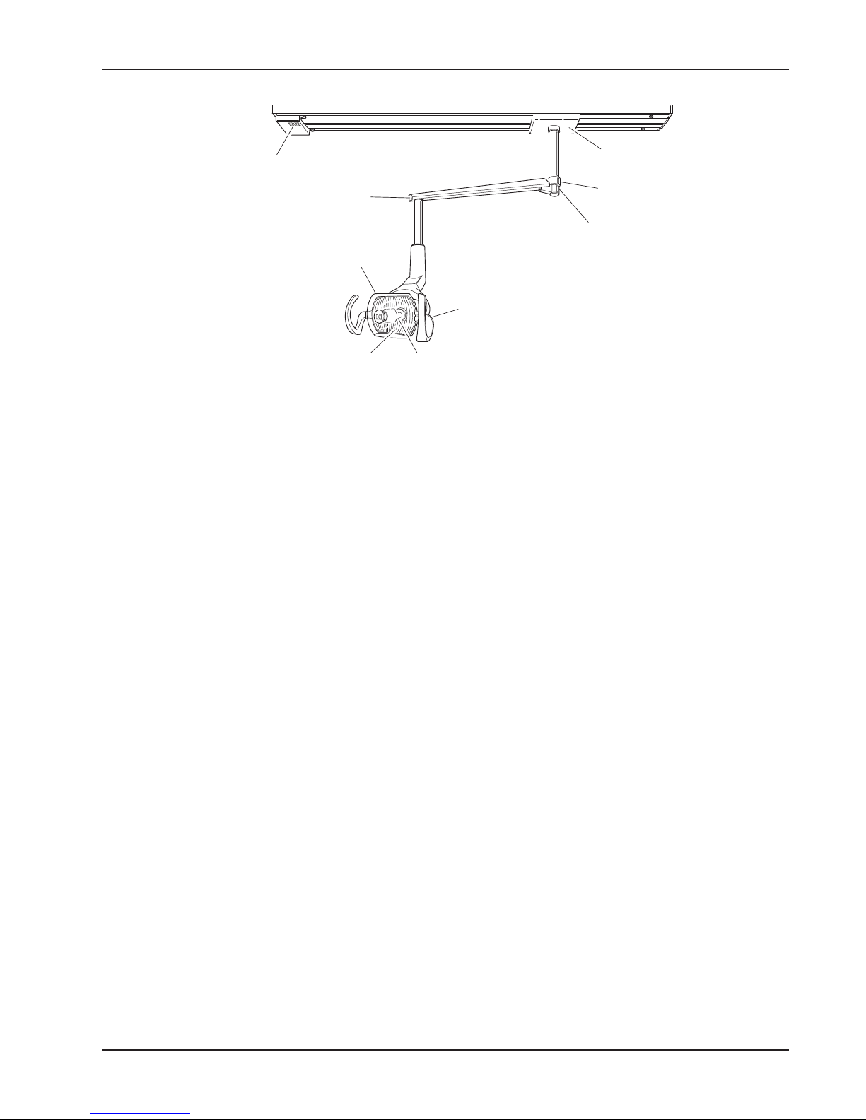
Overview / Replacement Parts............................................................................................................5
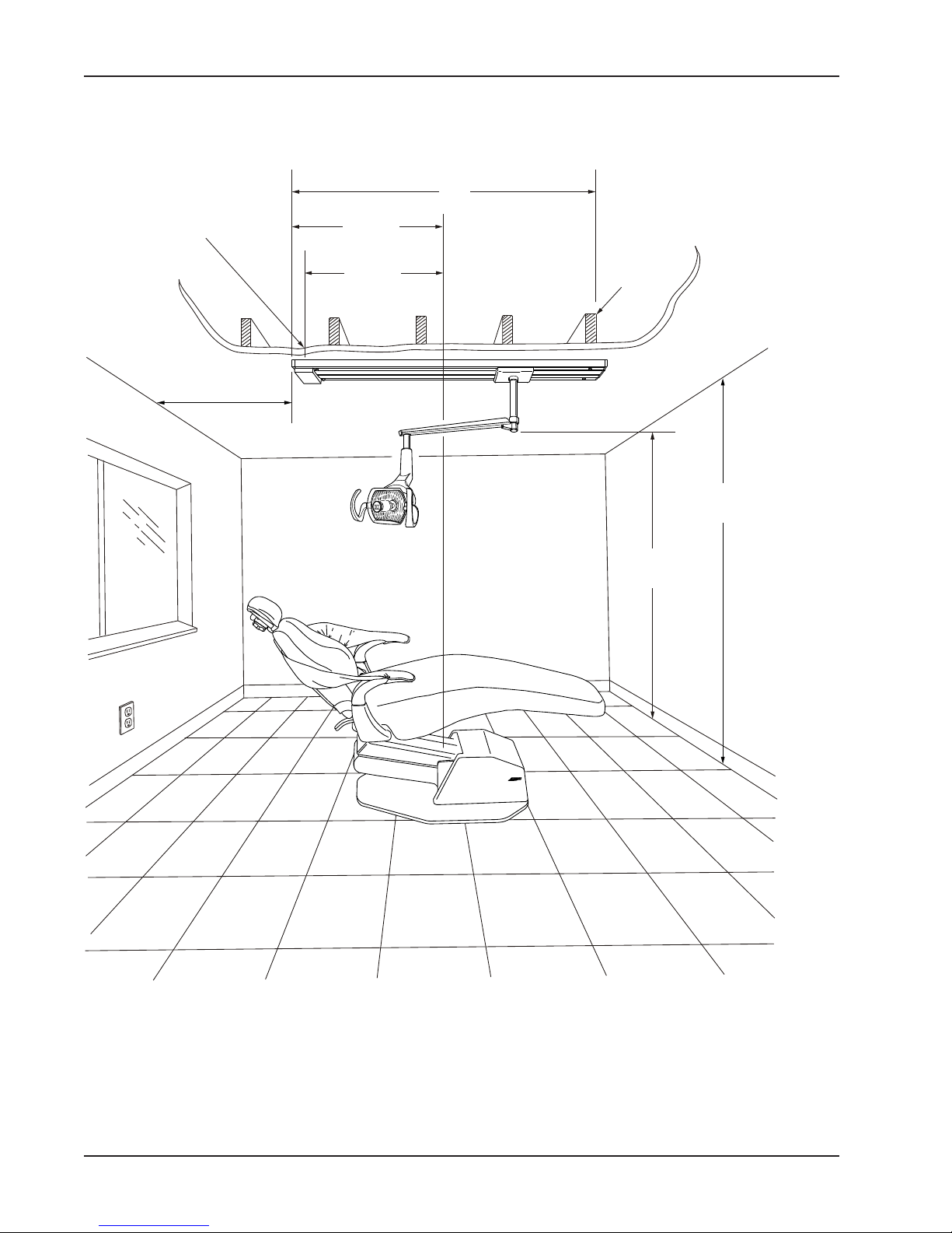
Suggested Mounting Methods.............................................................................................................6
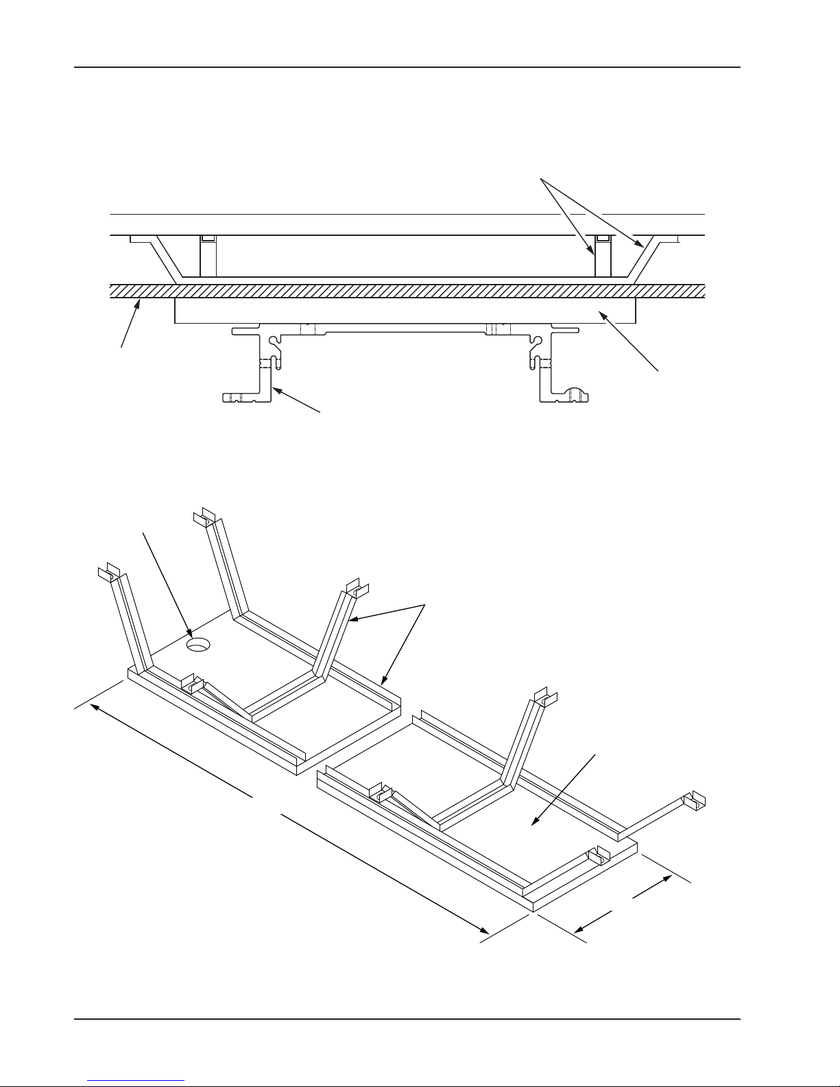
Suggestions for Suspended Ceiling ....................................................................................................7
Mounting Parallel and Perpendicular.............................................................................................9
Electrical Requirements.....................................................................................................................10
Installation Instructions......................................................................................................................10
Adjusting the Light-head’s Horizontal Rotation..................................................................................13
Adjusting the Light-head’s Vertical Rotation ......................................................................................13
Adjusting the Light-head’s Third Axis Rotation .................................................................................14
Focusing the Light .............................................................................................................................14
Turning the Light On and Off .............................................................................................................14
Replacing the Bulb ............................................................................................................................15
Adjusting the Auto-Switch(Optional)..................................................................................................16
Flex Arm Adjustment..........................................................................................................................16
Vertical.........................................................................................................................................16
Horizontal ....................................................................................................................................16
Cleaning the Light..............................................................................................................................17
WARNINGS, DISINFECTING & STERILIZATION - LIGHTS ......................................................17
Unacceptable Disinfectants.........................................................................................................17
Conditionally Acceptable Disinfectants* ......................................................................................17
Cleaning Reector and Cover .....................................................................................................18
Dimensions and Range of Motion - TL 500 Track Light.....................................................................19
Dimensions and Range of Motion - Light Head.................................................................................21
Service Location - Track Light Power Supply....................................................................................21
Service Location - Light Head ...........................................................................................................22
Electrical Schematics ........................................................................................................................23
Electromagnetic Compatibility ...........................................................................................................25
Checklist............................................................................................................................................29
Table of Contents

2
The following symbols may be used throughout
this manual:
CAUTION. Failure to carefully follow the described
procedure may result in damage to the equipment.
WARNING. Failure to carefully follow the described
procedure may result in damage to the equipment
and/or operator/patient injury.
Risk of electrical shock present.
Ensure power is disconnected before attempting
this procedure.
GENERAL INFORMATION
Denition of Symbols Product Disposal
Contact your local authorized dealer for proper disposal of the
device to ensure compliance with your local environmental
regulations.
Interference with Electromedical Devices
To guarantee the operational safety of electromedical devices, it
is recommended that the operation of mobile radio telephones
in the medical practice or hospital be prohibited.
Strong EMI sources such as electro surgery units or x-ray units
may affect performance. If performance problems occur, move
the light to another electrical circuit or physical location.
Incompatible Devices and/or Accessories
For reasons of product safety, only original manufacturer
devices & accessories approved for this product, or
accessories from third parties which have been released by the
manufacturer may be used. It is the user’s risk when using non-
released accessories are used.
Obtaining Technical Literature
The manufacturer will make available on request circuit
diagrams, component parts lists, descriptions, calibration
instructions or other information that will assist technical
personnel to repair and replace serviceable items.
Product Identication
This dental light can be identied by its product label, located
on product. This label states the light model and serial
number, electrical specications, manufacture date and safety
classication. Note the SAMPLE labels shown below.
Waste Electrical and Electronic Equipment
Protective Earth (Ground)
Manufacturing date
Type B Equipment
(Protected against electrical shock)
Dangerous Voltage
Electrical Testing Lab
AC (Alternating Current)
CAUTION: Only authorized service
technicians should attempt
to service this equipment.
Use of other than authorized
technicians will void the
warranty.
WARNING: This product must be
disinfected before use.
EN60601-1-2,UL60601-1
Dental Light
Marus
11727 Fruehauf Drive
Charlotte, NC 28273 USA
MN
SN
92162•Rev.5 •02/12
115 VAC, 60HZ, 1.09A
IEC Type B,Class 1, IPX4
Operation Mode: Intermittent
Conforms to:
Certified to:
CAN/CSA - C22.2 NO.601.1
59768
EN60601-1-2,UL60601-1
Dental Light
Marus
11727 Fruehauf Drive
Charlotte, NC 28273 USA
MN
SN
92163 •Rev.5 • 02/12
230 VAC, 50HZ, 0.6A
IEC Type B,Class 1, IPX4
Operation Mode: Intermittent
Conforms to:
Certified to:
CAN/CSA - C22.2 NO.601.1
59768
Authorized European Representative:
Medical Device and QA Services
76, Stockport Road
WA15 7SN
United Kingdom
e-mail: [email protected]
WARNING: This product is intended
for use by trained dental/medical
professionals only.
Identication mark that indicates the product
complies with the health & safety requirements
as published by European Directives.

3
CAUTION! Use a licensed electrician
for all wiring.
WARNING: Failure to disinfect the
dental operating light between patients
could expose user/patient to cross
contamination and bio-burden/bio-
contamination.
WARNING: To avoid risk of electric
shock, this equipment must be
connected only to supply mains with
protective earth.
WARNING: No modication of this
equipment is allowed.
WARNING: Power cords and their
associated parts cannot be substituted
without increase risk of electric shock
or re. Use manufacturer-approved
replacement parts only! Power
cords must be installed by qualied
personnel. Make sure all service
loops, strain reliefs, and cord guards
are in place and that line, neutral
and ground wires are secured.
WARNING: The light is not to be used
in rooms where an explosion hazard
exists.
WARNING: Rotational stops are
designed for a maximum force limit of
30 lbs. If rotational stops are broken
immediately take the equipment out of
use and have the equipment serviced.
Operation of damaged equipment
could result in injury to the operator
and/or patient.
Storage Conditions:
-55°C to +50°C
10% to 90% Relative Humidity
The pre-installation must be performed according to the requirements in our ‘Pre-installation Instructions’.
As manufacturers of electro-medical products we can assume responsibility for safety-related performance of
the equipment only if maintenance, repair and modications are carried out only by us or agencies we have
authorized for this purpose, and if components affecting safe operation of the unit that may be needed are
replaced with original parts.
We suggest that you request a certicate showing the nature and extent of the work performed, from those
who carry out such work, and specify that the certicate show any changes in rated parameters or working
ranges, as well as the date, the name of the rm and a signature.
SAFETY NOTES
WARNING: Failure to install set
screws & roll pin per Installation
Instructions could result in injury or
damage to equipment.
WARNING: To avoid risk of burn injuries
do not touch the light reector during
operation.
WARNING: To avoid risk of injury, avoid
contact with sharp edges on dental
lights.
CAUTION: Only authorized service
technicians should attempt to service
this equipment. Use of other than
authorized technicians will void the
warranty.
WARNING: To avoid risk of injury, avoid
contact with sharp edges on dental
lights.

4
Technical Specications for the Dental Light
Technical Description — Light
The dental light is used for illuminating the oral
cavity during the performance of dental procedures.
The position and direction of the light can be adjusted
as needed by the dentist. The light source is a halogen
bulb designed to operate on low voltage. It has two
intensity settings. The low voltage is supplied through a
transformer which is located at the top of the light pole
or in the junction box.
Replacement Parts for Dental Lights
The following represents a condensed list of
replacement parts that may be consumed during
normal use. See your dealer for a more compre-
hensive list of components.
PART # DESCRIPTION
70-22186 ................REFLECTOR, GLASS
70-20289 ................LIGHT SHIELD
70-30441 ................REPLACEMENT BULB
70-014R304............FUSE, 4 AMP, 3 AG (115V)
70-014R303............FUSE, 2 AMP, 3 AG (230V)
Electrical Specications
IEC Medical Device Classication
Classication: 1
Type: B
Operation Mode: Intermittent
Splash Protection: IPX4
Volts Cycles Amps
Dental light: 115 VAC 60 HZ 1.09 A ~
230 VAC 50 HZ 0.6 A ~
Replacement fuses for unit light
(located in panel near transformer):
115V: 4 AMP, 3 AG (P/N 70-014R304)
230V: 2 AMP, 3 AG (P/N 70-014R303)
Safety Markings
The following warning label may be located
on or near the light’s transformer enclosure:
Halogen Lamp: 24 Volts, 100 Watts
Input Voltage: 110V/220 V, 60/50 Hz
Output Voltage: High 23V, Low 21V
Color Temperature: 4500 Degrees Kelvin
Light Intensity (Lux): High 25,000, Low 18,500
Focal Distance: 27 in.
Illumination Area: 3 in. x 8 in. at Focal Distance
Approx. Weight: 9.09 kg. (20 lbs.)
Light Specications
Patent Pending for DCI Equipment Light Head
Device Classication
The dental light is classied as
Class 1 device under rule FDA
CFR 21, Class I device under
Health Canada guidelines, and a
Class I device under rule 11 of the
MDD 93/42/EEC of Annex IX.

5
Overview / Replacement Parts
Congratulations on your purchase of the MARUS Track Light! You have chosen a product that will provide
years of reliable, trouble-free service.
This manual contains instructions for installing, maintaining, and operating the TL 500 model Track light. Fol-
lowing these instructions will ensure smooth operation and a long life for your equipment.
The TL 500 Track Light features include:
• A sleek asepsis design that promotes simple, thorough cleaning.
• Ergonomic handles that reduce stress on wrists and hands.
• A light head that includes a third-axis positional adjustment for precise alignment with the oral cavity.
• Single-button shield removal and an easy to replace bulb that reduces costly service
calls.
• Smooth and quiet gliding track movement with optional trolley brake.
• An optional, adjustable auto-switch that automatically turns the light on when the ex
arm is lowered.
Serial / Model
Number
Set Screw
022R006
Trolley Assembly
52R304
Bushing Retainer
52R255
Reflector
22186
Yoke Pivot Cap
20317
Bulb
30441
Reflector Shield
20289
Front End Cap
52R110

6
Suggested Mounting Methods
Stub out wiring at
this point (1-1/4”)
access hole in
mounting pallet
64”
35-1/2”
33-5/8”
Chair
Centerline
42” min.
Recommended
Ceiling
joists
6‘-3”
+/-3”
8‘-0” min.
12’-0” max.

7
Suggestions for Suspended Ceiling
BE SURE TO BRACE
STRUCTURE IN BOTH
DIRECTIONS
MINIMUM SIZE 3/4”
PLYWOOD PANEL
77-5/8” x 10” WIDE
CEILING JOISTS
16” ON CENTER
LAG BOLTS (NOT INCLUDED)
LONG ENOUGH TO GO AT LEAST
3/4” INTO PLYWOOD PANEL
PRE-ASSEMBLED
FROM FACTORY

8
TRACK
PALLET
SUSPENDED
CEILING
PREFORMED
BRACKETS
PLYWOOD PALLET
77-5/8”
10”
1-1/2” DIA.
HOLE
1-1/2” x 3/4” x 1/8” CHANNELS
PREFORMED AND BOLTED TO
PLYWOOD PALLET
Suggestions for Suspended Ceiling - continued...

9
LAG SCREWS
3/4” PLYWOOD PALLET
TO BRIDGE CEILING JOIST
ALIGN 1-1/2” DIA.
HOLE WITH HOLE
LOCATED IN TRACK
Mounting Parallel and Perpendicular
Mounting parallel to ceiling
joist on new construction
Mounting parallel to ceiling joist
on existing construction
Mounting perpendicular
to ceiling joist
16”
16”
16”
16”
BRIDGE BETWEEN
CEILING JOIST AT
INTERVALS TO ACCEPT
MOUNTING SCREWS

10
The 115VAC/230VAC service line for
the track light should be evaluated
and installed by a licensed electri-
cian in accordance with local electri-
cal codes.
We recommend that a wall switch be
installed in the power supply to fa-
cilitate servicing and protect the light
transformer in the event of power
surges while the light is not in use
(i.e., electrical storms).
Electrical Requirements
*We recommend installation to be
performed by a qualied technician.
1. After the required support
structure is in place, remove
the track from its shipping
container. Remove the plastic
end cap from each end of the
track, remove the transformer
cover and remove the side trim
panels. The side trim panels
are removed by pulling straight
outward after the end caps are
removed. (See gure below).
2. Use 5/16” lag bolts (not in-
cluded) of a length that will
penetrate at least 3/4” into
solid wood to attach the pallet
to the ceiling or support struc-
ture. Holes can be drilled and
countersunk in other locations
along the edges of the pallet, if
required, to align with existing
ceiling joists or support struc-
ture. Be sure that the heads
of the lag bolts do extend
past the surface of the pallet.
The side trim extrusions will
not t unless the heads are
ush.
CAUTION: The ceiling or support structure and hard-
ware used must be capable of supporting 200 lbs. dead
weight.
Installation Instructions

11
3. Be sure that the power to the track light circuit is off
and make the necessary electrical connections. We
recommend that a licensed electrician make the
required power connections.
4. Assemble the post to the trolley. To do so, remove
the electrical bracket and insert the post into the
trolley, slide the coiled power cable into the post
and insert the cross pin. After being certain that the
cross pin is resting fully in its groove, re-install the
electrical bracket. Finally, tighten the two socket
head set screws to hold the post rmly in place.
(See gure at right).
5. Prior to installing the trolley onto the track, take a
few minutes to clean any debris from the track rails
that may be present from installing the track on the
ceiling.
Cross Pin
Set Screw
Set Screw
Installation Instructions - continued...
6. Remove the two trolley stops from the track by
pulling off the plastic cover and turning the stop
stud counter-clockwise until it unscrews from the
track. Slide the trolley onto the track being sure
that the wheels that are concave align with the
raised side of the track.
7. Plug the power cable into the trolley electrical
bracket being certain that the cord is curved
behind the trolley. (See gure at right).
8. Roll the trolley to approximately the center of
the track and re-install the stop studs removed in
step #6. Don’t forget to replace the plastic caps
onto the studs.
9. At this point, roll the trolley back and forth on the track several times to check for freedom of movement.
Also check that the trolley stays in place and does not drift to one end of the track. If the trolley tends to
drift toward one end of the track, place spacers between the opposite end of the track and the ceiling or
support structure to level the track. Recheck and add spacers as required until the track is level and the
trolley will remain stationary.
CAUTION: When adding or removing spacers, take steps to se-
cure the trolley in place on the track. Wedge a piece of cardboard
between the wheels and the track to keep the trolley in place.

12
Installation Instructions - continued...
10. Re-install the side trim extrusions, transformer cover, and end caps removed in step #1.
11. Place the locking tab retaining collar on the post just above the locking tab slot and lightly tighten the set
screw. CAUTION: OVERTIGHTENING THE SETSCREW WILL MAR THE PAINTED SURFACE.
16. This completes the installation of the TL 500 Track Light Assembly. Turn on the light and check for proper
operation and balance. The light head is fully assembled and functionally tested prior to leaving the fac-
tory. Should adjustments need to be made, please refer to the Adjustments section of this manual.
Setscrews
Light Adapter
Optional Placement
for Left Handed
Position
Locking Tab
Retaining Collar
Rotation Stop
Screw - Right
Hand Position
Power Plugs
13. The rotational stop screw is pre-
installed from the factory, but may
be necessary to change position
according to whether the opera-
tor is right or left handed. THIS
SCREW MUST BE USED IN
EITHER ONE OF THE TWO LO-
CATIONS. MALFUNCTION AND/
OR DAMAGE MAY RESULT TO
THE LIGHT IF THIS SCREW IS
REMOVED ENTIRELY.
14. Grease the light adapter and the
inside of the bottom of the post.
Have an assistant hold the light
assembly with the adapter near
the bottom of the post. Plug the
short male cord into the female
coiled cord rmly being certain
that this plug makes a tight con-
nection so as not to become
disconnected in the future. (See
gure at right).
15. Slide the light adapter into the bottom of the post until it bottoms. Look into the slot to be sure the stop
screw is not within the connes of the slot. Now place the locking tab into the slot in the side of the post.
The locking tab ts ush into the ceiling post. Now loosen the setscrew and the locking tab retaining collar
and lower it over the slot. Align the collar with the bottom of the post and tighten the setscrew rmly. The
assistant supporting the light can now release it. (See gure above).

13
Adjusting the Light-head’s Vertical Rotation
1. Remove the yoke end-caps on both
sides of the yoke assembly by grip-
ping the lip of the end-cap cover and
pulling straight out.
2. Using the special tool provided, tight-
en or loosen the adjustment screws
on both sides of the yoke as needed
to achieve the desired friction.
3. Make the adjustments in small in-
crements, checking the result after
each. Match the adjustment on each
side to achieve even friction.
To correct a stiff or loose movement:
Adjusting the Light-head’s Horizontal Rotation
1. Remove the plug located at the rear of the pivot housing.
2. Insert a 3/32” hex wrench into the tension screw. Tighten
or loosen the tension screw in small increments, test-
ing the movement as you go, until the desired tension is
achieved.
3. Reinstall the plug.
Plug
Pivot
adjustment
screw
Yoke end cap
Avoid pinching this wire
Caution! While making adjustments, avoid
pinching the wire that runs through the yoke
assembly. A short circuit can cause serious
damage to the light.

14
1. Using a 5/64” hex wrench, remove the
back cover of the pivot housing.
2. Using the special tool provided, tighten
or loosen the pivot nut in small incre-
ments until the desired level is set.
3. Reinstall the cover.
Adjusting the Light-head’s Third Axis Rotation
Focusing the Light
The light’s focus should be checked whenever
a bulb is replaced.
1. Point the light directly at a at surface, such
as a wall or a sheet of cardboard, position-
ing the bulb shield 27 inches away.
2. Turn the light on.
3. Using the knob at the back of the light,
adjust the focus to obtain the sharpest light
pattern.
Pivot nut
Back cover
Focus adjustment knob
Turning the Light On and Off
The light head has a three-position switch: up is
“high”, down is “low”, and middle is “off”.
The optional auto switch automatically turns on the
light when it is lowered for use and off when it is
lifted clear of the patient.
The three position switch must be in either the
“High” or “Low” position for the optional auto-switch
to turn on the light.
On/off and
intensity
switch

15
Replacing the Bulb
For maximum reliability and
optimum performance, use
replacement bulb no. 70-30441.
The bulb is a two-prong push-in type.
To replace a bulb:
1. Open the shield by pressing the re-
lease button and swinging the shield
open.
2. After waiting for it to cool, grasp the
old bulb by the base and pull straight
outward. A gentle rocking motion will
help work the bulb loose.
3. Grasp the new bulb by the base, align
the pins with the matching holes, and
press the bulb rmly into place.
4. Wipe the glass portion of the bulb
clean with denatured alcohol.
5. Close the shield by depressing the
shield release button while swinging it
shut until the latch is engaged.
6. Check the light’s focus and adjust as
required.
Shield
Bulb
Warning! Do not attempt
to remove a bulb until it
has been allowed to cool
for at least two minutes.
Caution! Do not to touch the glass
portion of the bulb. Oils from the
skin can cause the bulb to fail. If
you touch a bulb or reector, wipe
it clean with denatured alcohol
before turning on the light.

16
Adjusting the Auto-Switch(Optional)
The Switch assembly is clipped onto the light arm
tension rod. To change the position at which the light
activates:
1. To adjust the position at which the auto switch
activates, simply slide the switch bracket towards
or away from the switch bracket until the desired
position is attained.
Flex Arm Adjustment
Vertical
1. Remove the two socket head screws using
a 5/64 hex wrench.
2. Remove the ex arm cover.
3. Using a 1/2” wrench, adjust the tension bolt
until desired tension is set. Turn clockwise
for more tension; turn counter-clockwise for
less tension.
4. Replace cover and end caps.
Horizontal
If ex arm sways from side to side and will not
hold a steady position.
1. Make certain that the vertical mounting post
and track are level. Use spacing washers to
adjust as necessary.
Range of
adjustment
Contact turns light off
Tension rod
Auto switch
Tension
Bolt
Line up brackets
edge to alignment
mark
Slide actuator bracket
forward or backward
for adjustment

17
WARNINGS, DISINFECTING & STERILIZATION - LIGHTS
Infection control in the dental ofce continues to be a high
priority for our customers and end users. OSHA, the ADA
and the CDC are also involved in this complex issue. The
Manufacturer will not attempt to specify the required intervals
for disinfection nor can it recommend the overall best surface
disinfectant. Please refer to the:
Infection Control
Recommendations published by the American Dental
Association for further information. The question is often asked,
“What should I use to disinfect my dental unit, chair and light?”
This question is more complex than it seems because of the
wide variety of products on the market as well as formulations
of the products changing to meet the needs of increased
asepsis.
Barrier Technique
The Manufacturer strongly advocates the barrier technique
be used whenever possible to preserve the nish and
appearance of the equipment. Wherever possible disposable
barriers should be used and changed between patients.
The barrier technique will ensure maximum long term
durability of the surfaces and nishes of the equipment.
Chemical Disinfection
Regardless of the chemical disinfectant used, it is
imperative that the equipment be thoroughly washed with
mild soap and warm water at least once per day. This
wash down will minimize the harmful effects of chemical
disinfectant residues being allowed to accumulate on the
equipment. When using chemical disinfectants, always
pay strict attention to the manufacturer’s disinfectant
directions. When using concentrated disinfectants,
measure the concentrate carefully and mix according
to package directions. Disinfectant solutions that are
relatively harmless to surfaces at their recommended
strengths can be corrosive at higher than recommended
dilution ratios.
Only disinfect by wiping, no spray disinfection.
Please be aware that the manufacturer expressly
rejects any claims for warranty or damages when
using other cleaning and disinfections solutions.
*The Manufacturer makes no representation as
to the disinfectant efcacy of these products. We
make no warranty expressed or implied that these
disinfectants will not damage the surface nishes.
Damage and discoloration of the surface nishes
are not covered under the warranty.
**Iodophor-based disinfectants will cause yellow
staining on many surfaces.
Unacceptable Disinfectants
These disinfectants will harm the surface nishes of
dental equipment and are not recommended. Use
of these products will void your warranty.
Conditionally Acceptable Disinfectants*
These disinfectants have been found to be the
least harmful to the equipment surfaces by our test
methods.
Chemical Composition
Strong Phenols/Phenol Alcohol combinations
Sodium Hypochlorite/Household Bleach
Sodium Bromide
Strong Alcohol
Household Cleaners (Dental Equipment Only)
Citric Acids
Iodophors**
Ammonium Chloride
Accelerated Hydrogen Peroxide (0.5%)
Chemical Composition
Phthalaldehyde
Quaternary Ammonium
Glutaraldehyde
CAUTION
The equipment can be cleaned with a solution of mild detergent and warm water. A variety of surface disinfectants
are available for use in dental treatment rooms. Some of these can cause discoloration of painted, plated or anodized
surfaces with repeated use. This can be minimized by careful adherence to the disinfectant manufacturer’s instructions
and by frequent washing with soap and water. If you use an iodophor, it is especially important that you follow up with an
iodophor neutralizer.
IMPORTANT: Do not use powdered cleansers, scouring pads on abrasive scrubbers or any of the
painted, plastic or metal surfaces of this light. To remove dried-on material, use a soft bristled brush
and a solution of mild detergent.
Cleaning the Light

18
Cleaning the Light, Continued
Cleaning Reector and Cover
NOTE: Use only denatured alcohol to clean the glass reector. Use only mild soap and water to clean
the plastic reector cover.
Be sure the electrical supply is turned off and the light is cool before attempting any cleaning or polishing.
Remove the bulb shield, cover and bulb for full access to the reector. (See “Bulb Replacement” for bulb
removal).
Use a clean, soft** facial tissue dampened with denatured alcohol and gently wipe the surface of the reec-
tor and the bulb. The plastic reector cover may be gently washed with soap and water and dried using a soft
towel.
Cleaning Painted Surfaces
The painted surfaces of your light can be cleaned by simply wiping with a damp cloth. No other protective
coating is required to preserve the permanent luster of the painted surface.
CAUTION: Placing aluminum foil over the lamp handles for barrier asepsis will cause permanent discolor-
ation of the handles. We recommend covers specically manufactured for this purpose. Discoloration of the
handles caused by the above is not covered under warranty.
**We recommend Puffs facial tissues.
NOTE: The plastic reector cover must always be in place when light is used because it will
catch bulb particles in the rare event a bulb should break; also, it will keep abrasive material
away from the coated surface of the reector.
Do not use any solvents, abrasives, abrasive cloths or cleaners,
as they may damage the coated surface of the reector.
Table of contents
Other Marus Lighting Equipment manuals