manuals.online logo
Brands
  1. Home
  2. •
  3. Brands
  4. •
  5. Masco
  6. •
  7. Plumbing Product
  8. •
  9. Masco Brizo Loki 6572828 User manual

Masco Brizo Loki 6572828 User manual

12612.00 05.05
1
Models/Modelos/Modèles
6572828, 6472720
Series/Series/Seria
Lokit
Writepurchasedmodelnumberhere.
Escriba aquíelnúmero del modelocomprado.
Inscrivez lenuméro demodèleici.
Youmay need/Usted puedenecesitar/
Articlesdontvouspouvez avoirbesoin:
For easyinstallationofyour
BRIZOtfaucetyouwill need:
*ToREAD ALL theinstructionscompletely before
beginning.
*ToREAD ALL warnings,care,and maintenance
information.
*To purchasethe correctwater supplyhook--up.
Parainstalaciónfácil desullave
BRIZOtusted necesitará:
*LEERTODASlasinstruccionescompletamente
antesde empezar.
*LEERTODOSlosavisos,cuidados,einformación
demantemiento.
*Comprarlasconexionescorrectaspara elsuministro
deagua.
Pourinstaller votre robinetBRIZOt
facilement, vousdevez :
*LIRE TOUTESlesinstructionsavantdedébuter.
*LIRE TOUSlesavertissementsainsiquetoutes
lesinstructionsdenettoyage etd’entretien.
*Acheterlebon raccordementnécessaire pour
l’alimentationeneau.
TWO HANDLE LAVATORY AND BAR FAUCETS
MEZCLADORPARA FREGADERO
MELANGEUR A DOUBLE COMMANDEPOUR LAVABO
ET BAR
2mm,2.5mm,3mm
6572828 6472720
t
Note:The back edge of the faucetbody
mustbe atleast1”fromthe backsplash
on wall in orderto allowaccestothe lift
rod function.
Nota:La orilla posteriordel mecanismo/
cuerpo de lallave de agua debe estar
porlomenosa 1”delprotectorde yeso
de la pared para poderpermitiracceso
alafunción de la barrita paralevantarel
desagüe automático.
Note:Le côté arrièreducorpsdu robi-
netdoitsetrouveràaumoins1 po du
dosseretsurlemurpourque latirette
puisse bouger
Note:Thisfaucet fits1 3/8”min.
mounting holesize.
Note:Cerobinetva dansun trou
d’installation de 1 3/8”au minimum.
Nota:Espossiblemontarla unidad en
un orificiode13/8”.
r
CSAB125
ASMEA112.18.1
ICC/ANSIA117.1
r
2
12
Fig.1.
FAUCET INSTALLATION
A.ForLavatoryfaucets:Install liftrod.Insert thethreadedend oftherod inthe
holefromunderneaththefaucetand screwit intotheliftrod knob.Hand tighten
only.
B.Install themounting stud.Screwit intothefaucetand tightenit slightly.
C.Install theflexiblesupply hoses.Screwthehosesintothefaucetbody,taking
carenot to damagetheO--Ring sealing surface and hand tightenthehosesonly.
Nowrenchesarerequiredforthisassembly.
Note:If you cannotget theflexiblehosesthrough themounting holeby stagger-
ing thenippleson theflexiblehoses,insertoneofthehosesthrough themounting
surface fromunderneathand screwit intothebody justabovethedeck.
D.Insertfaucet intomounting surface.
E.Slipwasher(1)overthemounting stud and secureit with nut(2).
Option:If mounting surface isuneven,usesiliconesealantunderthefaucet in
place ofgasket.
HAGALASCONEXIONESALASLÍNEASDEAGUA:
Escoja conexionesde1/2”IPS:
(1)Tubo montantedebola(tuberíade cobre3/8”D.E.)o
(2)Conexión I.P.S.de1/2”parallaves.
Utilice lastuercasde acoplamientoincluídas(3)con lostubosmontantesdebola
(1).Utilice dosllavesdetuercascuando apriete(4).Noaprietedemasiado.
Fig.2
MAKECONNECTIONSTOWATERLINES:
Choosehook--upsfor1/2”I.P.S.connections:
(1)Ball noseriser (3/8”O.D.coppertubing),or
(2)1/2”I.P.S.faucetconnector.
Usethe enclosedcoupling nuts(3)withtheball noserisers(1).
Usetwowrencheswhentightening (4).Do notovertighten.
12
3
1/2” (12.70mm) IPS
RACCORDEZ LESTUYAUX D’EAU CHAUDEETD’EAU
FROIDE.
Choisissez desraccordscompatibles1/2”IPS:
(1)tubes--raccordsàportée sphérique(tube encuivre3/8”d.e.),ou
(2)raccordsderobinet1/2”IPS.
Sivousutilisez destubes--raccordsàportée sphérique(1),servez--vousdes
écrousderaccordementfournis(3).Utilisez deux cléspourserrerlesraccords
(4).Prenez gardedetrop serrer.
12612.00
1
2
4
INSTALACIÓN DE LALLAVEDEAGUA
A.ParalasLlavesdeLavamanos:Instalelabarritadelevantar.Introduzca enel
agujero,desdepordebajo delallavede agua,elextremoenroscado delabarray
atorníllelo dentro delpomo delabarritadelevantar.
B.Instale elperno prisionero demontaje.Atorníllelo dentro delallavede aguay
apriételo un poco.
C.Instalelasmanguerasflexiblespara elsuministro de agua.Atornillelasman-
guerasenel mecanismo delallavede agua,asegúreseno dañarlasuperficiesella-
doradelaroOyaprietelasmangueras sóloamano.Noserequierenllavesde
tuerca para este ensamblaje.
Nota:Sino puede alcanzarlasmanguerasflexiblesatravésdelagujero deinstala-
ción alternando lasentrerroscasenlasmanguerasflexibles,introduzca unadelas
manguerasatravésdelasuperficiedeinstalación desde el interioryatornílleloen
el mecanismojusto porencimadelasuperficiedelgabinete.
D.Introduzca lallavede agua enlasuperficiedeinstalación.
E.Deslice la arandela(1)sobre elperno prisionero demontajeyfíjela con latuer-
ca (2).
Opción:Si lasuperficiedeinstalación estádesnivelada,useselladordesilicón por
debajo delallavede agua en vez delempaque.
INSTALLATION DU ROBINET
A.Robinetsdelavabo -- Installez latirette.Introduisez l’extrémitéfiletée dela
tirettedansletrou parledessousdu robinetetvissez--ladanslebouton delati-
rette.Serrezàlamainseulement.
B.Installez legoujon demontage.Vissez--ledanslerobinetetserrez--lelégère-
ment.
C.Installez lestuyaux souples.Vissez lestuyaux dansle corpsdu robineten pren-
antsoin denepasabîmerlasurface d’étanchéitédesjointstoriques.Serrez--lesà
lamainseulement.Leserragen’exigepasde clé.
Note:Sivousnepouvez fairepasserlestuyaux souplesdansl’orifice demontage
en décalant lesraccords,faitesremonterl’un destuyaux souplesdansl’espace
videdelasurface demontage etvissez--ledansle corpsjuste au--dessusdela
plage.
D.Introduisez lerobinetdansl’espace videdelasurface demontage.
E.Faitesglisserlarondelle(1)surlegoujon demontage etfixez--la avec l’écrou
(2).
Facultatif: Si lasurface demontage est inégale,appliquez du composéd’étan-
chéitéàlasiliconesouslerobinetaulieu d’utiliserlejoint.
3
3
15
14
13
912
11
16
2
1
3
4
5
6
7
8
10
17
E.Colocarlapieza deplástico(8)dentro delcuerpo (9)yroscareste enlaválvula
(3).Nota:Elorificioroscado (16)debe estarorientado hacialallave.Empujar
hacia abajolaválvulayreajustarlaspiezascolocadasenelpasoD.
F.Colocarel tapón (2)dentro delaválvula(3).Colocarlapieza negra(11)enla
varilla(12)asulado corto.Colocartambiénlapieza deplástico(13)enla
varillaporsulado largo.
G.Introducirlavarilla(12)enelcuerpo (9).Apretarlatuerca de acoplamientoal
orificioroscado.
H.Unirlavarilla(12)al tornillo de apriete(14).Instalelabarritadelevantarel
desagüe(17)dentro delamordaza.(14).Apretarel tornillo(15)ycomprobar
elbuenfuncionamiento delsistema.
INSTALACIÓN DEL DESAGÜEAUTOMÁTICO.
A.Quitarelprotectordeplástico(1)yel tapón (2)delaválvula(3).
B.Desmontarelracordedesagüe(10)delcuerpo (9)aplicando TeflónÒala
zonaroscadadel tubo.Roscaréste(10)denuevo enelcuerpo (9).
C.Colocarlajuntadegomablanca (4)enlaválvula(3).Sepuedeutilizarun
cordón desiliconasisedesea.Introducirlaválvula enelorificio dedesagüe
del lavabo/fregadero,etc
D.Colocarlajuntadegomablanca (5),con su parte cónica hacia arriba,yla
juntadefibra(6)enlaválvula(3)pordebajo del lavabo/fregadero.Roscarla
tuerca (7)enlaválvula(3)peronoapretardefinitivamentetodavía.
Fig.3
POP--UPINSTALLATION
A.Removeplasticstoppercap(1)and stopper(2)fromflange(3).
B.Removetailpiece (10)frombody (9)and applyTeflonâtapetothreadson
tailpiece.Screwtailpiece (10)backinto body (9).
C.Slidewhitegasket(4)ontoflange(3).(Siliconemay beusedtoreplace gasket
ifdesired.) Insertflangeintosink.
D.Push black gasket(5),conesideup,and fiberwasher(6)ontoflange(3)from
undersink.Screwnut(7)ontoflange(3)butdo notsecurein place yet.
E.Place whiteplasticseal(8)into body (9)and screwbody (9)ontoflange(3).
Note:Pivot(16)mustface faucet.Pull assembly downand tighten nut/washer/
gasketon flange(3).
F.Place stopper(2)intoflange(3).Place blackseal(11)onto pivotrod (12)from
shortend and pivotnut(13)from long end.
G.Insertpivotrod (12)into body (9).Tighten pivotnut.
H.Attach pivotrod (12)toclamp(14).Install liftrod (17)intoclamp(14).Tighten
screw(15)and checkstopperoperation .
INSTALLATION DU VIDAGEAUTOMATIQUE
A.Enlevez le chapeau deprotection (1)et lebouchon (2)delabondeàbouchon
(3).
B.Enlevez leraccord devidage(10)du corps(9)etappliquez unebande adhési-
vedeTéflonÒaufiletagedu raccord devidage.Vissez leraccord devidage
(10)surle corps(9)denouveau.
C.Faitesglisserlejointblanc(4)surlabondeàbouchon (3).(On peutéventuel-
lementutilisersilicone aulieudujoint).Passez labondeàbouchon dansle
lavabo.
D.Poussez lejointnoir(5),avec le côté conique en haut,et lejointenfibre(6)
surlabondeàbouchon (3)dedessousdu lavabo.Vissez l’écrou (7)surla
bondeàbouchon (3)sansfixerencore en place.
E.Placez lejointen plastiqueblanche(8)dansle corps(9)etvissez le corps(9)
surlabondeàbouchon (3).Note: lemembredu pivot(16)doit êtretourné
verslerobinet.Tirez en basl’assemblage etserrez l’écrou et lesjoints surla
bondeàbouchon (3).
F.Placez lebouchon (2)danslabondeàbouchon (3).Placez lejointnoir(11)sur
latigehorizontale(12)àl’extrémité courte et l’écrou (13)àl’extrémitélon-
gue.
G.Placez latigehorizontale(12)dansle corps(9).Serrez l’écrou du pivot.
H.Fixez latigehorizontale(12)àlapièce deserrage(14).Installez latirette(17)
danslapièce (14).Serrez levis(15)etcontrôlez lefonctionnementdu bou-
chon.
12612.00
4
45
2
1
Fig.5
MAINTENANCE,SPOUT.
Toreplace yourspoutassembly orifthefaucet leaksaround thebaseofthe
spout,perform thefollowing steps:
A.Inserta2mm hexAllenwrenchintothesetscrew(1)whichislocatedjust
underthespoutplatformand loosenit as shown.Pull straightup on thespout to
removeit from thebody assembly.
B.If faucet leaksaround thebaseofthespout,replace thetwo o--rings(2)&(3)
and theguidering (4)on thespoutshank.
C.Examinethespoutsupportring (5)and replace it ifworn.
D.Whentheo--ringshavebeenreplaced,carefully pushthespoutassembly
backintothefaucetbody and tightenthesetscrewusing a2mm hexAllen
wrench.
Fig.4
FLUSHYOUR SYSTEM
Remove aerator(1)and turnfaucethandle(2)tothefull on mixed position.
Turn on hotand coldwatersuppliesand flushwaterlinesforoneminute.
Important: Thisflushesawayany debristhatcouldcausedamagetointernal
parts.
Checkall connectionsforleaks.Re--tightenifnecessary,butdo notover-
tighten.
PURGAR SUSISTEMA
Quite elaireador(1)y girelamanijadelallave(2)alaposición
completamente abierta enmixta.Abralos suministrosde agua calienteyfríay
deje correrelaguaporlaslíneasporun minuto.
Importante:Estolimpia cualquierescombro quepueda causardaño alas
partesinternas.
Verificartodasuniones sihayfugas.Apretardenuevo,sinecesario,no apriete
demasiado.
MANTENIMIENTO,SURTIDOR.
Parareemplazarsumontajedelsurtidorosi lallavede aguasefiltra alrededor
delabasedelallavede agua,lleve a cabo losiguiente:
A.Introduzca unallaveAllen hex de2mm enel tornillo de ajuste(1)que está
ubicado casipordebajo delaplataformadelsurtidoryaflójelocomosemues-
tra.Hale,enelsurtidor,directamentehaciafuera,parasacarlo delensamble
del mecanismo.
B.Si lallavetienefiltración alrededordelabasedelsurtidor,reemplace los
dosArosO(2)y(3)yelaro deguía(4)enla espigadelsurtidor.
C.Examine elaro desoportedelsurtidor(5)yreemplácelosiestádesgastado.
D.Cuando hayareemplazado losarosO,cuidadosamentepresioneotravez el
ensambledelsurtidorenlallavede aguayapriete el tornillo de ajusteusando
unallaveAllen hex de2mm.
RINCEZ LE ROBINET
Enlevez l’aérateur(1)et tournez lamanette(2)en position d’ouverturemaxima-
le.Rétablissez l’alimentation eneauchaude eteneaufroide et laissez couler
l’eau pendantuneminute.
Important: lefait delaissercoulerl’eau permetd’évacuerlescorpsétrangers
quipourraientabîmerlescomposantsinternesdu robinet.
Contrôlez touslesassemblages s’il yadesfuites.Reserrez sinécessaire,mais
prenez gardedenepastrop serrer.
ENTRETIEN:BEC
Pour remplacerlebec ou encasdefuiteparlabasedu bec,suivez lesins-
tructionsquifigurentci--après.
A.Introduisez une cléAllen hexagonalede2mm danslavisde calage(1)
quiestsituée justesousleplateau du bec etdesserrez--la commelemontrela
figure.Tirez directementsurlebec pourl’extrairedu corps.
B.Si lerobinetfuit parlepourtourdelabasedu bec,remplacez lesdeux
jointstoriques(2)et(3)et l’anneau--guide(4)surlatigedu bec.
C.Examinez l’anneau d’appuidu bec (5)etremplacez--les’il estusé.
D.Aprèsavoir remplacé lesjointstoriques,réintroduisez lebec dansle corps
du robinetenlepoussantdoucementetserrez lavisde calageàl’aided’une
cléAllen hexagonalede2mm.
12612.00
2
3
2
4
1
5
2mm
5
6
Fig.6
MAINTENANCE,HANDLE COVER.
Toreplace a handle cover,perform thefollowing steps:
A.Thereisasmall hole(4mm)on thebottomsideofthehandle cover.Locate
theholewith your fingerand withthetip ofasmall Allenwrench push up on
thetabinsidethishole and pull the coveroff horizontallyas shown.
B.Pushthenewcoverontothehandle assembly,making surethesmall holeis
on thebottomand that thetabsnapsintotheholetosecurethe cover.
12612.00
MANTENIMIENTO,CUBIERTA DE LAMANIJA.
Para cambiarla cubiertadelamanija,lleve a cabo los siguientespasos:
A.Hay un pequeño agujero(4mm)enlapartede abajo delcostado dela
cubiertadelamanija.Ubique elagujerocon su dedoycon lapuntadeuna
llaveAllen pequeñalevantelalengüetadentro delagujeroysaquela cubierta
horizontalmente comosemuestra.
B.Presionela cubiertanueva enelensambledelamanija,asegureque el
agujero pequeño quede enlapartede abajo y quelalengüetaquede colocada a
presión enelagujero para asífijarla cubierta.
ENTRETIEN:COIFFEDEMANETTE
Pour remplacerune coiffedemanette,suivez lesinstructionsquifigurent
ci--après.
A.Ilyaun petit trou (4mm)aufond dela coiffedelamanette.Localisez le
trou avec ledoigt,puispoussez surlapatteàl’intérieurdu trou avec l’ex-
trémitéd’unepetite cléAllenet tirez surle couvercleàl’horizontale comme
lemontrelafigure.
B.Poussez lanouvelle coiffesurlamanette en vousassurantquelepetit trou
setrouvedu côtéinférieuretquelapattesebloquedansletrou pourim-
mobiliserla coiffe.
6
7
12612.00
4
5
2
3
Fig.7
MAINTENANCE,CERAMIC VALVES.
Ifyourfaucetleaksoutof the end of thespout,perform thefollowingsteps:
Note:Determineifyourspout isleaking hotorcoldwaterby checking thewaterdripping
outofthespout.
Turnoff thewater suppliesbefore working onyourfaucet.
A.Removespoutassemblyasdescribedinsection 5.
B.If you havedeterminedthatonly one cartridgeisleaking (eitherhotorcold)onlyre-
movethatonehandle assembly.Toreplace boththehotand coldcartridges,both handle
assembliesneedsto beremoved.
Thehandle assemblycan beremovedbyinserting a3mm hexAllenwrenchintotheset
screws(1)and unscrewing themas shownabove.Removebothscrews.Repeaton the
oppositesideifbothcartridgesarebeing replaced.
C.Nextusea2.5mm hexAllenwrenchtoremovethethree screws(2)thatholdsthe
body tothemounting plate.
D.Pull straightup on thebody toremoveit from thebase.
Note:Theliftrod and knob assemblywill slideoutofthebody asyou pull up and will be
heldin place by thebasewhichremains securedtothemounting surface.Thisisnormal.
E.Using aPhillips screwdriver,removethescrew(3)thatholdstheleverontothestemof
the cartridge.
Repeat thison thesecond stem ifyou arereplacing bothcartridges.
F.Using ascrewdriverand small hammer,taponthetop ofthestem to pushit outofthe
body.
G.Replace theoldcartridgewithanewone(4).Same cartridgeforeachside.
H.Examinetheseatrings(5)and replace ifnecessary.
MANTENIMEINTO,VÁLVULASDECERÁMICA.
Sisullavedeagua goteadesde elsurtidor,lleveacabolos siguientespasos:
Nota:Determinesisullavequegotea esde aguafríaocaliente chequeando elaguaque
estágoteando delsurtidor.
Cierre los suministrosdeagua antesdetrabajar ensullavedeagua.
A.Quite elensambledelsurtidorde agua comosedescribe enlasección 5A.
B.Sisehadeterminado que elaguase estáfiltrando esdesolouncartucho (fríaoca-
liente)sólo quitelamanijaquelepertenece a dicho cartucho.Para cambiaramboscartu-
chos,fríoycaliente,sedeben quitarambosensamblesdelasmanijas.
Elensambledelamanijasepuedesacarintroduciendo unallaveAllen hex de3mm en
lostornillosde ajuste(1)y destornillándoloscomosemuestra arriba.Quite ambostornil-
los.Siva a cambiaramboscartuchos,repita elprocedimientoenel lado opuesto.
C.Luego useunallaveAllen hex de2.5mm parasacarlostrestornillos(2)quesujetanel
mecanismo dela chapademontaje.
D.Haledirectamentehaciafuera el mecanismo desdelabase.
Nota:Labarritadelevantareldesagüeyelensambledelpomosedeslizarán del mecanis-
mocuando loshalaysemantendrá ensusitio porlabasequepermanece fijaalasuper-
ficiedelainstalación.Estoesnormal.
E.Usando un destornilladorPhillips,quite el tornillo(3)quesujetalapalanca enla espiga
delcartucho.
Siestá cambiando amboscartuchos,repitalomismoenlasegunda espiga.
F.Usando un destornilladoryunmartillo pequeño,golpee suavementelapartede arriba
dela espigaparasacarladel mecanismo.
G.Cambie elcartucho viejo(4)porelnuevo.Esel mismocartucho para cadalado.
H.Examinelosaros selladores(5)ycámbielos siesnecesario.
ENTRETIEN:CARTOUCHESEN CÉRAMIQUE
Encasdefuiteparl’extrémitédu bec,suivez lesinstructionsquifigurentci--après.
Note:Voyez si l’eau quidégouttedu bec estchaudeou froide.
Interrompez l’alimentationeneauavantde commencer àtravailler surle robinet.
A.Retirez lebec conformémentaux instructionsdelasection 5A.
B.Sivousconstatez qu’uneseule cartouchefuit (celled’eauchaudeou celled’eau
froide),retirez uniquement lamanettedela cartouchequifuit.Pour remplacerlescar-
touchesd’eauchaude etd’eaufroide,vousdevez enleverlesdeux manettes.Pourenlever
unemanette,introduisez une cléAllen hexagonalede3mm danslesvisde calage(1)et
desserrez--lescommelemontrelafigure ci--dessus.Enlevez lesdeux vis.Répétez l’opéra-
tion du côtéopposésivousdevez remplacerlesdeux cartouches.
C.Ensuite,utilisez une cléAllen de2,5mm pour retirerlestroisvis(2)quiretiennent le
corpsàlaplaquedemontage.
D.Tirez surle corpsdirectementpourleretirerdesabase.
Note:Alorsquevoustirez,latirette etson bouton glissenthorsdu corps,mais sont
maintenusparlabasequidemeurefixéeàlasurface demontage.C’estnormal.
E.Àl’aided’un tournevisPhillips,enlevez lavis(3)quiretient leleviersurlatigedela
cartouche.Faitesdemêmepourladeuxièmetigesivousremplacez lesdeux cartouches.
F.Àl’aided’un tournevisetd’un petit marteau,frapperledessusdelatigepourextraire
celle--cidu corps.
G.Remplacez lavieille cartouche(4)parune cartoucheneuve.Lescartouches sont iden-
tiquesdesdeux côtés.
H.Examinez lesbaguesdesiège(5)etremplacez--lesau besoin.
1
3mm
2.5mm
7
8Fig.8
MAINTENANCE,CERAMIC VALVES,REASSEMBLY.
A.Wheninserting thenewcartridgeintothebody,pleasepayspecialattention
totheflats(NB!) on the cartridge and body.Thesemustbe alignedin orderto
fullyseat the cartridge.Inaddition,asyou arepushing thenewcartridgein
place,thestem levermustbe alignedand orientedas shownin viewabove
beforethe cartridgeisfullyseatedin place.
Note:Levermarked”1” upwards,totheleftside and levermarked”2” up-
wards,totherightside.
Once theleverand cartridge are alignedcorrectly,pushuponthe cartridge
from thebottom tofullyseat it.
Repeatforthesecond cartridgeifnecessary.Again,payspecialattention tothe
cartridge and leveralignmentas shownabove.
B.Assemblethescrew(3)backintothestemunit tosecurethelever(1)&(2)
tothestemofthe ceramicvalve(6).
C.Place/pushtheseatrings(5)backintothebaseplate.
D.Align theliftrod knob intotheslot intheback ofthebody.Notethat the
slotand knob aretapered.
E.Carefully pushthebody assembly back overtheseatson thebaseplate.
F.Securethebody tothebaseplateby using a2.5mm hexAllenwrenchto
re--assemblethethree body screws(4).
12612.00
3
4
5
6
2.5mm
NB!
NB!
MANTENIMIENTO,VÁLVULASDECERÁMICA,REEN-
SAMBLE.
A.Cuando introduzca elcartucho nuevo enel mecanismo,por favorpreste aten-
ción especialalaspartesplanas(NB!) delcartuchoyel mecanismo.Estas
debenalinearseparaquequedensentadascompletamente enelcartucho.
Además,cuando estápresionando elcartucho nuevo ensusitio,la espigade
palanca debe estaralineaday orientada comosemuestra eneldiagramade arri-
ba antesque elcartucho quedetotalmentesentado ensusitio.
Nota:Lapalanca marcada con un ”1” hacia arriba,hacialaizquierdaylapalan-
ca marcada con un ”2” hacia arriba,hacialaderecha.Unavez quelapalanca y
elcartucho esténcorrectamente alineados,presione elcartucho desdelaparte
inferiorparasentarlocompletamente.
Siesnecesariorepita con elsegundo cartucho.Otravez,preste atención es-
pecialala alineación delcartuchoylapalanca comosemuestra arriba.
B.Ensambleotravez el tornillo(3)enlaunidad dela espigaparafijarlapalanca
(1)y(2)ala espigadelaválvulade cerámica.
C.Coloque/presioneotravez losarosde asiento(5)enla chapadebase.
D.Alinee elpomo delabarritadelevantardentro delamuesca aldorso del
mecanismo/cuerpo.Notequelamuesca yelpomoestánahusados
E.Cuidadosamentepresioneotravez el mecanismosobrelosarosde asientoen
la chapadebase.
F.Fije el mecanismoenla chapadebaseusando unallaveAllen de2.5mm para
reensamblarlostrestornillosdel mecanismo/cuerpo (4).
ENTRETIEN:RÉASSEMBLAGEDES SOUPAPESÀ CARTOUCHEDE
CÉRAMIQUE
A.Lorsquevousintroduisez lanouvelle cartouchedansle corps,portez une
attention particulière aux méplats(NB!) surle corpset la cartouche.Ilsdoivent
coïnciderpourquela cartouchepuisseseplacercorrectement.Deplus,lorsque
vouspoussez lanouvelle cartouchepourlamettre en place,assurez--vousquele
levierdelatige estaligné etorienté commelemontrelafigure ci--dessusavant
detenterde calerla cartouche en place.
Note:Levierportant le chiffre”1”àlaverticaledu côtégauche et levierport-
ant le chiffre”2”àlaverticaledu côtédroit.Unefoisquelelevieret la car-
touchesontalignéscorrectement,calez la cartouche enexerçantunepression
sursapartieinférieure.Faitesdemêmepourladeuxième cartouches’il yalieu.
Encoreunefois,assurez--vousquela cartouche et leleviersontalignéscomme
lemontrelafigure ci--dessus.
B.Remettez lavis(3)danslatigepour fixerlelevier(1)et(2)àlatigedela
cartouche encéramique.
C.Remettez lesbaguesdesiège en place (5)danslaplaquedebase en poussant
surcelles--ci.
D.Faitescorrespondrelatirette avec larainure au dosdu corps.Ilestànoterque
larainure et lebouton sontconiques.
E.Replacez soigneusement le corps surlesbaguesdesiègequisetrouventdans
laplaquedebase.
F.Fixez le corpsàlaplaquedebase en utilisantune cléAllen de2,5mm pour
serrerletroisvisdu corps(4).
8
9
12612.00
Fig.9
MAINTENANCE,SLIDEHANDLES,REASSEMBLY.
A.Important: Makesure that thelever comingfrom thestemispushedall
theway tothebackof theslotonthebody.See viewabove.
Align theopening inthetabat theback ofthehandle assemblywiththetip of
thestem leverand pushthehandle assemblyin place.Assemblethehandle,
using a3mm hexAllenwrench,withthetwoscrews(7)which had beenre-
movedearlier.
B.Makesurethat thelargeplasticsupportring isin place on thebody.
Place thespoutabovethebody and pushstraightdown until it is seated.Reas-
semblespoutasdescribedinsection 5.
7
NB!
NB!
NB!
3mm
MANTENIMIENTO,MANIJASDESLIZABLES,REENSAMBLE.
A.Importante:Asegúresequelapalancaquesaledelaespiga lapresione
completamentehacia atrásdelamuescaenelmecanismo.Vea arriba.
Alinee la aberturadelalengüeta aldorso delensambledelamanija con la
puntadelapalanca dela espigay presione elensambledelamanija ensusitio.
Ensamblelamanija,usando unallaveAllen de3mm,con losdostornillos(7)
quesacóanteriormente.
B.Asegúreseque elaro grandedeplásticoesté ensusitioenel mecanismo.
Coloque elsurtidorencimadel mecanismosobre éstey presionedirectamente
hacia abajo hastaquequedesentado.Ensamble elsurtidorotravez comose
describe enlasección 5.
ENTRETIEN:REMISE ENPLACEDESMANETTESÀGLIS-
SIÈRE
A.Important--Assurez--vousquelelevier fixéàlatige estenfoncé complète-
mentdanslarainure du corps.Reportez--vousàlafigure ci--dessus.
Faitescorrespondrel’ouverturedanslapatte au dosdelamanette avec l’extrémi-
tédu levier fixéàlatige etpoussez lamanetteàsaplace.Fixez lamanette à
l’aided’une cléAllen hexagonalede3mm etdesdeux vis(7)quiontétédépo-
séesplustôt.
B.Assurez--vousquelegrosanneau d’appuien plastiquesetrouvesurle corps.
Placez lebec surle corpsetenfoncez--ledirectement jusqu’àcequ’il soit calé.
Réassemblez lebec conformémentaux instructionsdelasection 5.
9
6572828
6472720
sPlease specifyfinishwhen ordering thisreplacementpart.
sSedeberá especificarelacabado cuando pida estapiezaderecambio.
sVeuillezspécifierlefiniàlapassation de commandede ces pièces détachées.
BN =BrillianceRBrushedNickel
Nosuffixisrequiredforchrome.
Para cromonoes necesariounsufijo.
Aucun suffixe n’estexigépourchrome
14
1
21
3
15
4
9
19
26
25
23
22
24
20
12612.00
18
10
21
7
8
13
12 5
6
16
3
25.RP38907s
Flange
Válvula
Bondeàbouchon
26.RP38906s
Stopper
Tapón
Bouchon de vidage
2
2
11
17
12
2--2.5--3mm
1.RP44132s
LavatorySpout,Complete
Surtidorcompleto para elLavamanos
Bec completpour robinetdelavabo
2.RP44133
Guide&O--RingsforSpout
GuíayArosOpara elSurtidor
Guide etjointstoriques pourbec
3.RP44134
Supportring forspout
Aro deSoportepara elSurtidor
Anneau d’appuipourbec
4.RP44135
Bodymounting screws,3pc.
3Tornillosparalainstalación delmecanismo/cuerpo
Visdemontagedu corps,3 éléments
5.RP44136s
Slidehandle,coldside,complete
Manijadeslizable, lado frío,completa
Manetteàglissière complète,côté eaufroide
6.RP44137s
Handle cap,coldside
Tapadelamanija, lado frío
Capuchon demanette,côté eaufroide
7.RP44138
Ceramic valve
Válvulade cerámica
Cartouche encéramique
8.RP44139
SeatRing
Aro deAsiento
Baguede siège
9.RP44140
Gasket/O--Ring
Empaque/AroO
Joint/Joint torique
10.RP44141s
Lift rod,complete
Barritaparalevantareldesagüe,completa
Tirette complète
11.RP44181s
Knob forlift rod
Pomo paralabarritaparalevantareldesagüe
Bouton detirette
12.RP44175
Lock screwforspout
Tornillofiadorpara elsurtidor
Visde calagedu bec
13.RP44176s
Handle cap,hotside
Tapaparalamanija, lado caliente.
Capuchon demanette,côté eauchaude
14.RP44177s
Slidehandle,hotside,complete
Manijadeslizable, lado caliente,completa
Manetteàglissière complète,côté eauchaude
15.RP44178
Leverand screwforhandle
Palancaytornillo paralamanija
Levieretvispourmanette
16.RP44179s
Bar/PrepSpout,Complete
Surtidorpara elfregadero deBar/Prep., completo
Bec completpour robinetdebarou d’îlot
17.RP44184
Hex2-- 2.5-- 3mm Allenkeys
Llaves AllenHex de2-- 2.5-- 3mm
Clés Allen hexagonale2-- 2,5-- 3mm
18.RP36296
Hose
Flexo
Flexible
19.RP5861
Coupling nuts
Tuercas de acoplamiento
Ecrousdebranchement
20.RP28823
Nut&washer
Tuerca y arandela
Écrou etrondelle
21.RP36252s
Aerator
Aireador
Aérateur
22.RP38909s
Pop--up waste,complete
Vaciadorautomático,completo
Soupapede vidage,complète
23.RP38908
PivotSeat&Gasket
Asiento pivoteyjunta
Jointetsiègedu pivot
24.RP36271
Clampwithscrew
Anillo de apriete con tornillo
Pièce de serrage avec vis
10
Toutesles pièceset lesfinis du robinetBRIZOtsontprotégéscontreles défectuosités dematé-
riauet les vices defabrication parunegarantiequiestconsentie au premieracheteuretquide-
meurevalidetantque celui--cidemeurepropriétairedesamaison.Deltarecommandedefaire
appelàun plombiercompétentpourl’installation et laréparation du robinet.
Pendant lapériodedegarantie,DeltaremplaceraGRATUITEMENTtoutepièce ou toutfini,
présentantunedéfectuositédematériau ou un vice defabrication pourautantquel’appareil ait été
installé,utilisé etentretenu correctement.Pourobtenirdes piéces derechange,veuillez communi-
querpartéléphone au numéro 1--877--345--BRIZO(2749) (aux États--Unis ou auCanada)etpar
écrit àl’unedesadresses suivantes:
AuxÉtats--Unis
DeltaFaucetCompany
ProductService
55 E.111thStreet
Indianapolis,IN46280
AuCanada
DeltaFaucetCanada
Centredeservicestechniques
420 Burbrook Place
London,OntarioN6A4L6
PLACEMENTD’UN ÉLÉMENTAINSIQUE LES PERTESOU DOMMAGESDE TOUTE AUTRE
NATURENESONTPASCOUVERTS PARLA GARANTIE.Touteréclamation en vertu delaprésen-
tegarantiedoit être adresséeàDelta,accompagnée delapreuved’achat(originaldelafacture)du
premieracheteur.CETTE GARANTIE EST LASEULE OFFERTE PARDELTAFAUCET COMPANY
OUTDELTAFAUCET CANADA.SELON LE CAS.ELLE EXCLUT TOUTE AUTREGARANTIE,Y
COMPRISLA GARANTIEIMPLICITE DEQUALITÉ MARCHANDE.
Cettegarantie exclut toutusageindustrielou commercialou dans les places d’affaires,dont les
acheteurs sontcouverts parunegarantielimitée de cinq ans quiprend effetà compterdeladate
d’achat.Touteslesautresconditions delagarantiede cinq ans sont identiquesà celles delaprésente
garantieàl’exception deladurée de celle--ci.Laprésentegaranties’appliqueàtous lesrobinets
BRIZOtfabriquésaprèsle1erjanvier2004.
Dans les États ou les provinces òu il est interdit d’exclureou delimiterlesresponsabilitésàl’égard
des dommagesindirects ou fortuits,lesexclusions et leslimites susmentionnées nes’appliquentpas.
Les dommagesrésultantd’unemauvaiseutilisation,d’uneutilisation abusivedelanégligence ou de
l’utilisation depiècesautres quedes pièces d’origineDeltaâRENDENT LA GARANTIENULLE
ET SANSEFFET.
Laprésentegarantievous donnedes droits précis quipeuventvarierselon votrelieu derésidence.
Ellenes’appliquequ’aux robinetsBRIZOtinstallésaux États--Unis,auCanada etau Mexique.
All partsand finishes oftheBRIZOtfaucetarewarrantedtotheoriginalconsumerpurchaserto
befree fromdefectsinmaterialand workmanshipforaslong astheoriginalconsumerpurchaser
owns theirhome.DeltaFaucetCompany recommends using aprofessionalplumber forall in-
stallation and repair.
Deltawill replace,FREE OFCHARGE,during thewarranty period,any partor finish thatproves
defectiveinmaterialand/orworkmanship undernormal installation,use and service.Replacement
partsmay beobtainedbycalling 1--877--345--BRIZO(2749) (intheU.S.and Canada)orby
writing to:
Todaslas piezas y acabados delallaveBRIZOtetán garantizados alconsumidorcomprador
original,de estarlibres dedefectos dematerialyfabricación,porel tiempo que elconsumidor
compradorsea dueño desu casa.DeltaFaucetCompany recomiendaqueuseun plomero
profesionalparatodaslasinstalaciones y reparaciones.
Deltareemplazará,LIBREDECARGO,durante elperíodo degarantía,cualquierpieza oacabado
quepruebetenerdefectos dematerialy/ofabricación bajoinstalación normal,uso y servicio.
Piezas derepuesto pueden serobtenidasllamando al1--877--345--BRIZO(2749) (enlos Estados
Unidos y Canada)oescribiendo a:
IntheUnited States:
DeltaFaucetCompany
ProductService
55 East111thStreet
Indianapolis,IN46280.
InCanada:
DeltaFaucetCanada
TechnicalService Centre
420 Burbrook Place
London ON N6A4L6
Enlos Estados Unidos:
DeltaFaucetCompany
ProductService
55 East111thStreet
Indianapolis,IN46280
EnCanada:
DeltaFaucetCanada
TechnicalService Centre
420 Burbrook Place
London ON N6A4L6
COMOTAMBIÉNCUALQUIEROTROTIPO DEPÉRDIDA O DAÑOSESTÁN EXCLUIDOS.
Pruebade compra(recibo originaldeventa)delcompradorconsumidororiginaldebedeser
disponibleaDeltaparatodos los reclamos.ESTAESLA GARANTÍAEXCLUSIVA DEDELTA
FAUCET COMPANY,QUENO HACECUALQUIEROTRA GARANTÍA DECUALQUIERTIPO,
INCLUYENDO LA GARANTÍAIMPLÍCITA DECOMERCIALIZACIÓN.
Estagarantía excluyetodo uso industrial,comercialy denegocio,cuyos compradores seles da
unagarantíalimitada extendidade cincoaños desdelafechade compra,con todos los otros
términos de estagarantía aplicados,exeptoeldeduración de ésta.Estagarantía esaplicablealas
llaves deBRIZOtfabricadas después deEnero 1,2004.
Algunos estados/provincias no permitenla exclusiónolimitación dedaños incidentales o
consecuentes,demaneraquelalimitaciónoexclusión arriba escritapuedeno aplicarleausted.
Cualquierdaño a estallave,resultado demaluso,abuso,o descuido,ocualquierotro uso de
piezas derepuesto queno sean genuinas deDeltaâANULARÁN LA GARANTÍA.
Estagarantíaledaderechos legalesespecíficos,y usted puedetambiéntenerotros derechos que
varian de estado/provinciaaestado/provincia.Es aplicablesóloalasllavesBRIZOtinstaladasen
los Estados Unidos deAmerica,Canaday Mexico.
CLEANINGAND CARE
Careshould begiventothe cleaning ofthis product.Although itsfinish isextremely durable,it
can bedamaged by harsh abrasives orpolish.To clean,simplywipegentlywithadampclothand
blotdrywithasoft towel.
LIFETIMEFAUCET AND FINISHLIMITEDWARRANTY
WELL ASANY OTHERKIND OFLOSS ORDAMAGESARE EXCLUDED.Proofofpurchase
(originalsalesreceipt) from theoriginalconsumerpurchasermustbemade availabletoDeltafor
all warrantyclaims.THISISTHE EXCLUSIVEWARRANTYBY DELTAFAUCET COMPANY,
WHICH DOESNOT MAKEANY OTHERWARRANTY OFANY KIND,INCLUDING THE
IMPLIEDWARRANTY ORMERCHANTABILITY.
Thiswarrantyexcludesall industrial,commercialand business usage,whosepurchasersare
hereby extendedafiveyearlimitedwarrantyfrom thedateofpurchase,withall otherterms of
thiswarrantyapplying except theduration ofthewarranty.Thiswarrantyisapplicableto
BrizotfaucetsmanufacturedafterJanuary 1,2004.
Somestates/provinces do notallowthe exclusion orlimitation ofincidentalorconsequential
damages,so the abovelimitation orexclusion may notapplyto you.Any damagetothisfaucet
asaresult ofmisuse,abuse,orneglect,orany useofotherthan genuineDeltaâreplacement
partsWILL VOIDTHEWARRANTY.
Thiswarranty gives you specificlegalrights,and you mayalso haveother rightswhich vary
fromstate/province to state/province.Itapplies onlyforBrizotfaucetsinstalledinthe
UnitedStates ofAmerica,Canada,and Mexico.
Thiswarrantyisextensiveinthatitcoversreplacementofall defectivepartsand evenfinish,but
these aretheonlytwothings thatare covered.LABOR CHARGESAND/ORDAMAGEIN-
CURREDININSTALLATION,REPAIR,OR REPLACEMENTAS
ã2004,MascoCorporation of Indiana
LIMPIEZA Y CUIDADODESULLAVE
Debedetenercuidado enlalimpieza de esteproducto.Aunquesu acabado esextremadamente
durable,puedeserdañado porabrasivos o pulimentos ásperos.Paralimpiarsimplementefrote
suavemente con un paño húmedo,y séquelocon un paño suave.
GARANTÍALIMITADA DEPOR VIDA DE LALLAVEYSU ACABADO
Estagarantía esextensiva enlo que cubre elreemplazamiento detodaslas piezas defectuosas y
hasta elacabado,peroéstas son las únicas dos cosas que estáncubiertas.CARGOSDE LABOR
Y/O DAÑOSINCURRIDOSENLAINSTALACIÓN,REPARACIÓN,OREEMPLAZAMIENTO
INSTRUCTIONSDENETTOYAGE
Ilfaut lenettoyeravec soin.Mêmesison finiestextrèmementdurable,il peutêtre abîmépardes
produitsfortementabrasifs ou des produits depolissage.Ilfautsimplement lefrotterdoucement
avec un chiffon humide et lesécheràl’aided’un chiffon doux.
GARANTIEÀ VIE LIMITÉE DESROBINETSET DE LEURSFINIS
Laprésentegaranties’applique auremplacementdetoutesles pièces défectueuses,ycomprisle
fini,etellene couvreque ceséléments.LES FRAISDE MAIN D’OEUVREET(OU)LESDOM-
MAGES PROVOQUÉSAU COURSDE L’INSTALLATION,DE LARÉPARATION OU DU REM--
ã2004,Division deMascoIndiana
ã2004,MascoCorporatión deIndiana
12612.00

This manual suits for next models

5

Other Masco Plumbing Product manuals

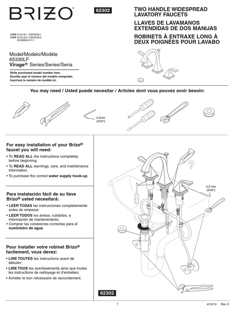
Masco Brizo Virage 65330LF User manual

Masco

Masco Brizo Virage 65330LF User manual

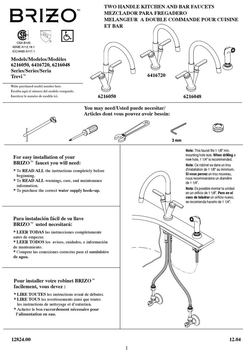
Masco Brizo Trevi Series User manual

Masco

Masco Brizo Trevi Series User manual

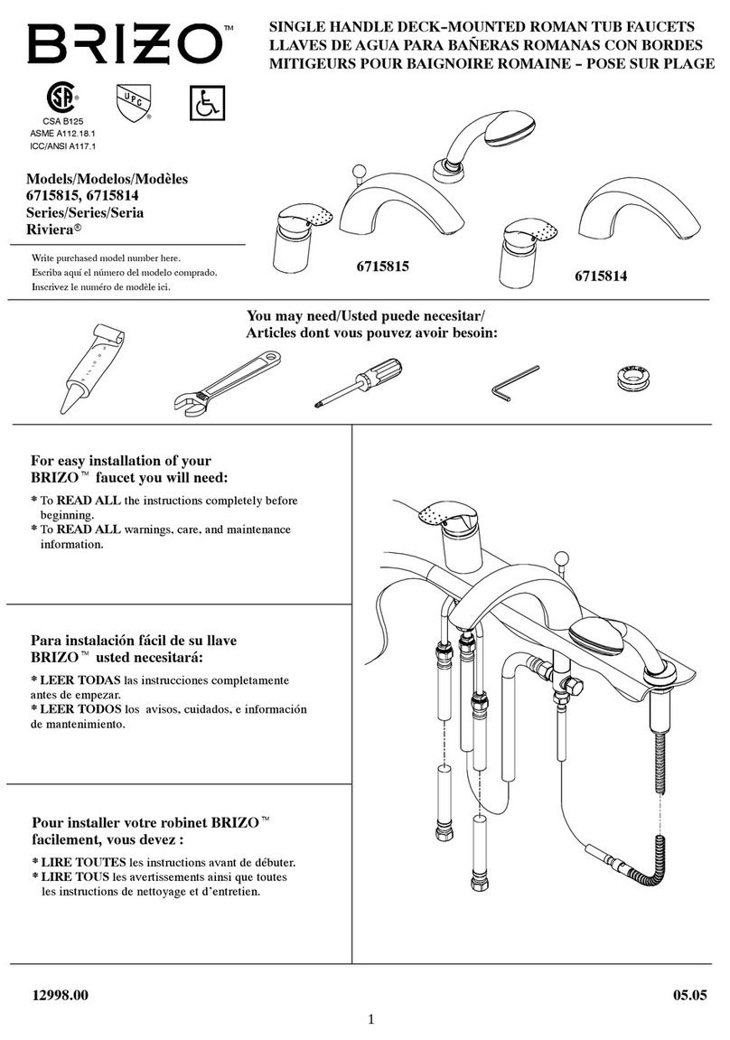
Masco Brizo Riviera 6715815 User manual

Masco

Masco Brizo Riviera 6715815 User manual

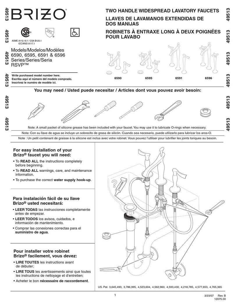
Masco Brizo RSVP 6590 User manual

Masco

Masco Brizo RSVP 6590 User manual

Popular Plumbing Product manuals by other brands

Gessi OVALE 23049 manual

Gessi

Gessi OVALE 23049 manual

Hans Grohe Logis 71130000 Instructions for use/assembly instructions

Hans Grohe

Hans Grohe Logis 71130000 Instructions for use/assembly instructions

Triton Shannon Installation and operating instructions

Triton

Triton Shannon Installation and operating instructions

Creavit BV8500 Installation instruction

Creavit

Creavit BV8500 Installation instruction

Hans Grohe Metropol S 14061 Series Instructions for use/assembly instructions

Hans Grohe

Hans Grohe Metropol S 14061 Series Instructions for use/assembly instructions

Waterstone 3300 installation instructions

Waterstone

Waterstone 3300 installation instructions

Thetford C500 Demounting instruction

Thetford

Thetford C500 Demounting instruction

Hans Grohe PULSIFY 24170670 Assembly instructions

Hans Grohe

Hans Grohe PULSIFY 24170670 Assembly instructions

Sanela SLWN 08P Mounting instructions

Sanela

Sanela SLWN 08P Mounting instructions

Gessi OVALE 23099 manual

Gessi

Gessi OVALE 23099 manual

Oras Electra 6150F Installation and maintenance guide

Oras

Oras Electra 6150F Installation and maintenance guide

Symmons SRT-4172 Installation and service instructions

Symmons

Symmons SRT-4172 Installation and service instructions

Fantini Rubinetti ICONA R067 instructions

Fantini Rubinetti

Fantini Rubinetti ICONA R067 instructions

Dyson AB 06 installation guide

Dyson

Dyson AB 06 installation guide

Ezipex Crimp Technical manual

Ezipex

Ezipex Crimp Technical manual

Oliveri 883U Product specifications

Oliveri

Oliveri 883U Product specifications

HIKE CREW HCCHH7701562 user guide

HIKE CREW

HIKE CREW HCCHH7701562 user guide

Bradley Advocate AV Series Installation

Bradley

Bradley Advocate AV Series Installation

manuals.online logo
manuals.online logoBrands
  • About & Mission
  • Contact us
  • Privacy Policy
  • Terms and Conditions

Copyright 2025 Manuals.Online. All Rights Reserved.