Doc.Ref.No.:m92A/om/101
Issue No.:20
Page | 1
+
A
PPLICATION
E
XAMPLE
I
SOLATED
C
ONVERTER
9000U
S
ERIES
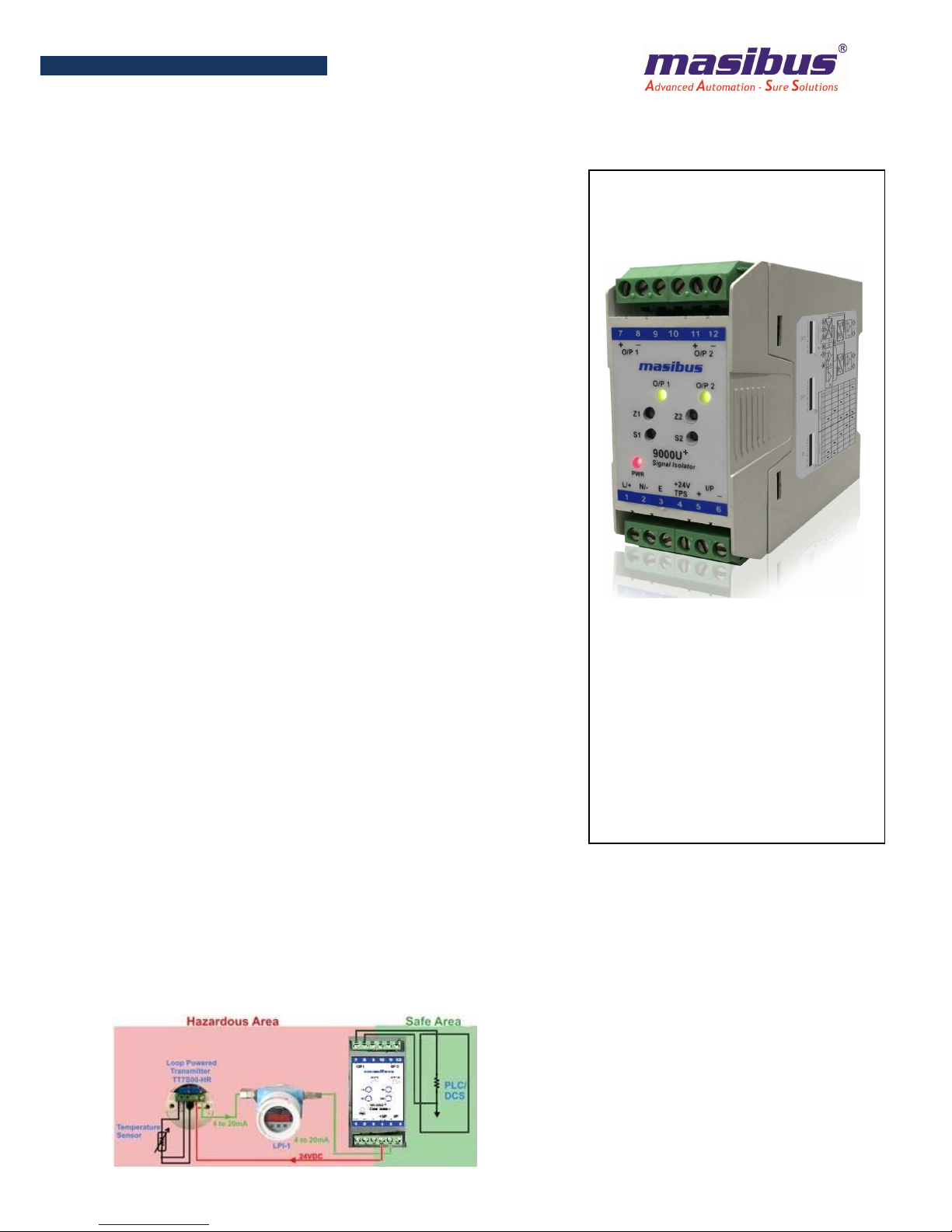
•9000U
+
Series are compact yet rugged 4 wire Signal isolators
designed for conditioning and safe guarding custom-built wide
range of voltage and current field signals. Field Signal is then
isolated and converted to standard instrumentation signals,
acceptable to commercially off the shelf (COTS) automation
products.
•Equipped with Advanced Extended Power Supply Range of
20V to 265V AC or DC.
•9000U
+
Series offer a wide range of input / output signal types
like mA, mV, VDC which are factory settable as per user
requirements. 9000U
+
model is further enhanced with Switch
selectable I/O configuration for I/O ranges i.e. 0/4-20mA, 0/1-
5V and 0-10V. This feature allows user to have freedom to
change 0/4-20mA, 0/1-5V and 0-10V I/O types only, using
switch available on side of device and with minor tuning using
front accessible trim-pots, depending upon field requirements.
•9000U
+
is equipped with Built in transmitter power supply
(TPS) that can drive filed transmitters in case of 4-20mA DC
input signal.
•9000U
+
Series isolators acts as signal distributor when used
with more number of outputs.
•9000U
+
Offers excellent accuracy and stability delivering
reliable operation in hostile environments with full 3 port
isolation between input, output and power supply.
•9000U
+
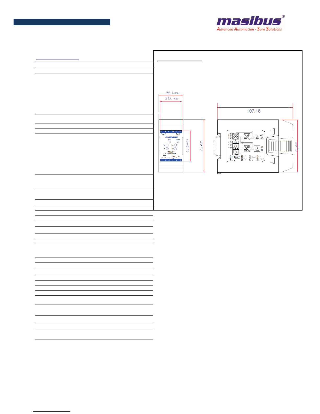
Series are flexible for DIN rail mounting and easily
installable. Its compact design consumes less space and hence
reduces cost of overall installation.
F
EATURES
•Slimmest in its class: 35 mm Single output and Dual output
•Extended Universal Power Supply Range:20V to 265V DC or
AC Capable to provide Safe and Sufficient Power For Field
Transmitter
•“Active Output” LED indication for Both Voltage and Current
Outputs
•Rugged & accurate 4 wire isolator
•Up to 2 outputs with Short Circuit Protection
•Wide zero & span adjustment limits
•2.0KV AC Isolation between I/P, O/P and Supply
•High CMRR and NMRR
•High output Load Driving Capability
•Non-standard Input and Output options also available
SOP & DOP
•Universal AC/ DC Aux. supply
•Front Calibration Facility
•Signal Isolator, dual output
•Three port isolation
•Excellent long term stability
•Built in transmitter’s power
•Compact DIN rail enclosure